6.3.5. 66AK2G02 ICE EVM Hardware Setup
6.3.5.1. Description
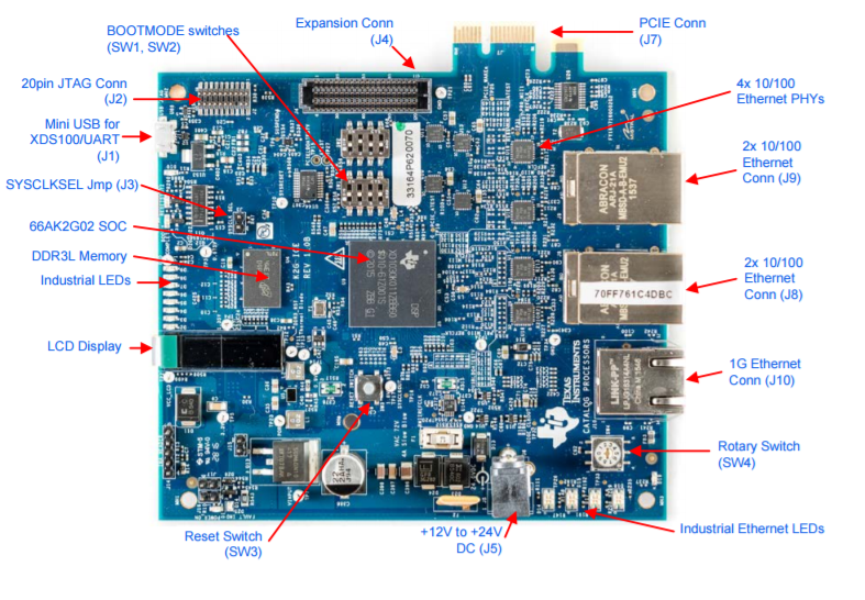
The K2G ICE EVM is a high performance, cost-efficient, standalone development platform that enables users to evaluate and develop industrial communications applications for the Texas Instrument’s Keystone2 System-on-Chip (SoC) 66AK2G02. The K2G SOC (66AK2G02) is the new device from TI’s Keystone II architecture with
- ARM® Cortex® -A15 Microprocessor Unit (ARM A15) Subsystem at up to 600MHz
- C66x Fixed- and Floating-Point VLIW DSP Subsystem at up to 600MHz
- Two Programmable Real-Time Unit and Industrial Communication Subsystems (PRU-ICSS)
- Multicore Shared Memory Controller (MSMC) with 1024KB of Shared L2 RAM
- Up to 36-Bit DDR3 External Memory Interface (EMIF) with ECC (32-Bit Data + 4-Bit ECC)
- PCI-Express® 2.0 Port with Integrated PHY
- Three Multichannel Audio Serial Port (McASP) Peripherals
- Multichannel Buffered Serial Port (McBSP)
- Six Enhanced High Resolution Pulse Width Modulation (eHRPWM)
The key features of the EVM are:
- K2G SoC 66AK2G02 is based on keystone II architecture with ARM cortex A15 @600MHz and C66x DSP @600MHz
- 515MByte of DDR3L
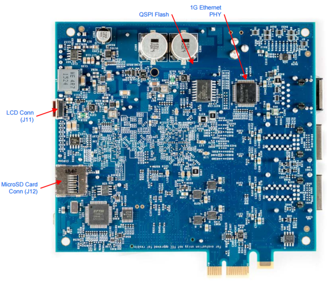
- 512Mbit of QSPI Flash
- 128kByte of I2C EEPROM
- Micro SD-Card slot
- Gigabit Ethernet port supporting 10/100/1000 Mbps data rate on RJ45 connector
- 4x 10/100 Industrial Ethernet connectors
- PCIe x1 card edge connector
- LCD display
- Expansion connector for customer designs
- XDS100 Emulator and UART over mini-USB connector
- 20-Pin JTAG header to support all types of external emulator
- RoHS compliant design
- Powered by DC power-wall adaptor (24V/2.5A) or PCIE Edge Connector
6.3.5.3. Supported JTAG Debug Probes (Emulators)
- XDS100-class JTAG debug probes (low cost, low performance). The XDS100v1 is not supported.
- XDS200-class JTAG debug probes (recommended)
- XDS560v2-class JTAG debug probes (high performance)
6.3.5.4. Minimal EVM setup
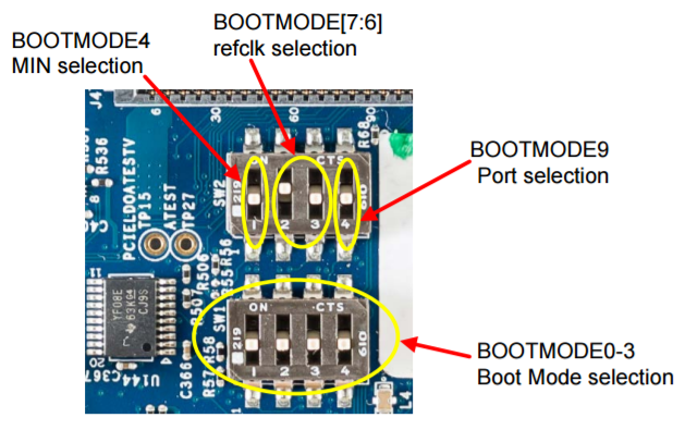
6.3.5.4.1. Setting Boot Switches
The DIP switch (SW3) is used for selecting the boot mode.
For the EVM Out-of-Box experience, use SD/MMC boot mode as shown in the image below:
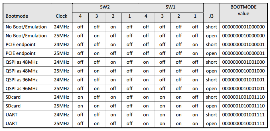
The table below lists all of the boot modes supported on the ICE EVM.
6.3.5.4.2. Connecting an Emulator
Note
This EVM setup is only required for developers who need to connect to cores using Code Composer Studio (CCS) to load their application.
The EVM supports two types of emulation via the on-board XDS100 emulator or the 20-pin JTAG header.
When an external emulator is not connected to the 20-pin JTAG Header, the on-board XDS100 embedded JTAG emulator is the default type of emulation (SoC JTAG signals are routed to the XDS100 on-board emulator). When an external emulator is connected to the 20-pin JTAG Header, it is automatically detected and the SoC JTAG signals are routed to the external emulator.
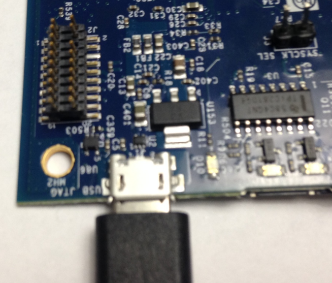
On-board XDS100 Emulator
The K2G ICE EVM has on-board XDS100 embedded JTAG emulation circuitry so an external emulator is not required. Users can connect to the target SoC via CCS by connecting the USB cable, supplied in the ICE EVM kit, as shown in the image below.
20-pin JTAG Header for Connecting an External Emulator
Users have the option of connecting an external at the 20-pin JTAG Header connector (EMU1). The 20-pin JTAG Header is provided on-board for high speed real-time emulation. All JTAG and EMUxx signals are terminated on 20-pin JTAG Header.
6.3.5.4.3. Powering Up the EVM
Power Supply Specifications
The K2G ICE EVM can be powered from one of two sources. A single +24V / 2.5A DC (60W) external power supply connected to the DC power jack (J6). In addition, the K2G ICE EVM can be powered from the 12V supply pins on the PCIE edge connector. A power ANDing circuit is included in the design which will prevent damage if the +24V is connected while the board is installed on a PCIE backplane. The +24V supply will supply the power for the board in that condition.
6.3.5.5. CCS Setup
This section describes the setup to connect to 66AK2G02 ICE EVM using Code composer Studio environment and an emulator.
There are two scenarios while connecting to the EVM :
- Connect to EVM without a SD card boot image to boot the EVM
- Connect to EVM after booting an image from the SD card.
Note
Keystone II device support package in CCSv7.1 includes the support for K2G ICE board but CCSv7.0/ CCSv6 users may need to update the device support package as described in the section “Update CCS to Install Keystone II Device Support Package.”
6.3.5.5.1. Update CCS to Install Keystone II Device Support Package
All revisions of the board require this step to be performed in order to get the latest GEL files and the target content for the K2G if you are using CCSv7.0 and earlier. This step will not be required for CCS versions higher than version 7.1. CCSv7.0 or CCSv6.1.3 package contain KeystoneII device support package v1.1.6 which doesn’t contain K2GICE specific target files hence we recommend this update.
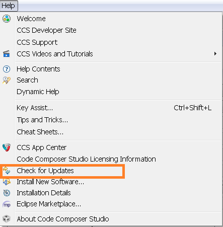
1. All CCS v6.1.3 or CCSv7.0 and earlier version users are required to update the Keystone Device Support package by going into the Help->Check For Updates
2. Select Keystone2 device support package. Follow menu options to continue with the update.
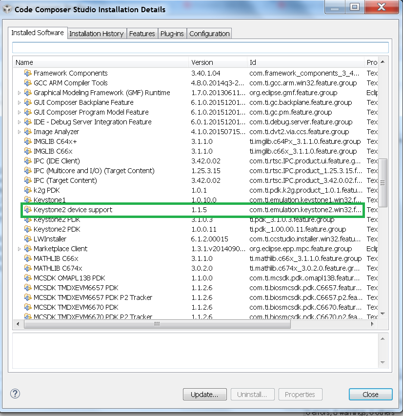
3. After the update is complete go to Help->Installation details and check that Keystone2 device support package v1.1.9 or later are installed as shown below.
Note
The package can be downloaded separately from the link below and manually unzipped into CCS installation.
Note
For K2G Devices, if using CCS v6.1.2 and Keystone2 device support v1.1.7, 66AK2G02 would not show up in the list of devices when creating the target configuration. This is due to an incompatibility in the XML parser in CCS v6.1.2 with the K2G device xml. In order to work-around this issue, make the change in 66AK2G02.xml as illustrated below in order to have 66AK2G02 display in the device list. This problem does not exist in CCS v6.1.3 onwards as the XML parser has been updated.
C:\ti\ccsv6\ccs_base\common\targetdb\devices\66AK2G02.xml
Line #1
<?xml version="1.1" encoding="UTF-8" standalone="no"?>
to
<?xml version="1.0" encoding="UTF-8" standalone="no"?>
6.3.5.5.2. Connect without an SD Card Boot Image
Configuring target configuration files
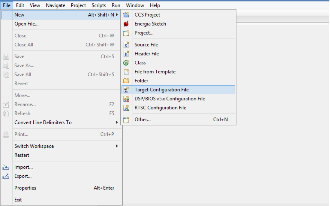
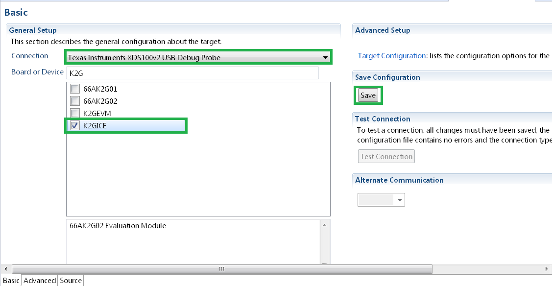
Launch CCS and create a new target configuration (File->New->Target Configuration file) as shown in the images below.
Provide an appropriate name to the configuration. Select Spectrum Digital XDS100 emulator and target as K2G ICE EVM.
Note
If you don’t find the K2GICE target make sure you have installed CCSv7.1 or higher. If using CCSv 7.0 or CCSv6.1.x and earlier, ensure that you have done the software update correctly as shown in the how to section below.
In advanced settings, make sure that the GEL files are populated correctly. The following GEL files and their corresponding cores are provided below.
- C66X Core: icek2g.gel
- A15 Core: icek2g_arm.gel
Connecting to target
1. Download Code composer Studio or for CCSv7.0 and earlier, ensure it contains Keystone device support package version 1.1.9 as described in the how to guide “Update CCS to Install Keystone II Device Support Package.”
2. 66AK2G02 ICE EVM contains boot switches to configure for “No boot/sleep” mode. So configure the boot switches to “No Boot Mode” as described in the “Setting Boot Switches” section.
3. Connect an XDS100 Emulator to the XDS USB port of the ICE EVM as shown in the section “Connecting Emulator.”
4. Launch CCS and create a new target configuration as discussed in the previous section “Configuring target configuration files.”
5. Launch the newly created target configuration.
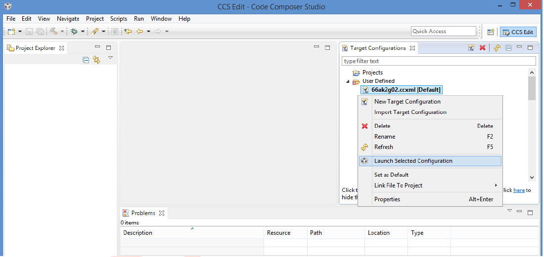
6. K2G can be a DSP or an ARM master boot device so connect to the C66x or the A15_0.
GEL Log
A15_0: GEL Output: PLL has been configured (24.0 MHz * 100 / 1 / 4 = 600.0 MHz)
A15_0: GEL Output: ARM PLL has been configured with ref clock 24MHz, -sysclkp_period 41.6666 (24.0 MHz * 100 / 1 / 4 = 600.0 MHz)
A15_0: GEL Output: Power on all PSC modules and DSP domains...
A15_0: GEL Output: Power on PCIE PSC modules and DSP domains... Done.
A15_0: GEL Output: UART PLL has been configured (24.0 MHz * 128 / 1 / 8 = 384.0 MHz)
A15_0: GEL Output: NSS PLL has been configured (24.0 MHz * 250 / 3 / 2 = 1000.0 MHz)
A15_0: GEL Output: ICSS PLL has been configured (24.0 MHz * 250 / 3 / 10 = 200.0 MHz)
A15_0: GEL Output: DSS PLL has been configured (24.0 MHz * 198 / 12 / 16 = 24.75 MHz)
A15_0: GEL Output: DDR PLL has been configured (24.0 MHz * 250 / 3 / 10 = 200.0 MHz)
A15_0: GEL Output: XMC setup complete. A15_0: GEL Output: DDR3 PLL Setup ...
A15_0: GEL Output: DDR3 PLL Setup complete, DDR3A clock now running at 400MHz.
A15_0: GEL Output: DDR3A initialization complete
6.3.5.5.3. Connect with an SD Card Boot Image
1. Launch CCS and create a new target configuration (File->New->Target Configuration file) as shown in the images below.
Provide an appropriate name to the configuration. Select Spectrum digital XDS100 emulator and target as 66AK2G02.
Note
If you don’t find the K2GICE target make sure you have installed CCSv7.1 or higher. If using CCSv 7.0 or CCSv6.1.x and earlier, ensure that you have done the software update correctly as shown in the how to section below.
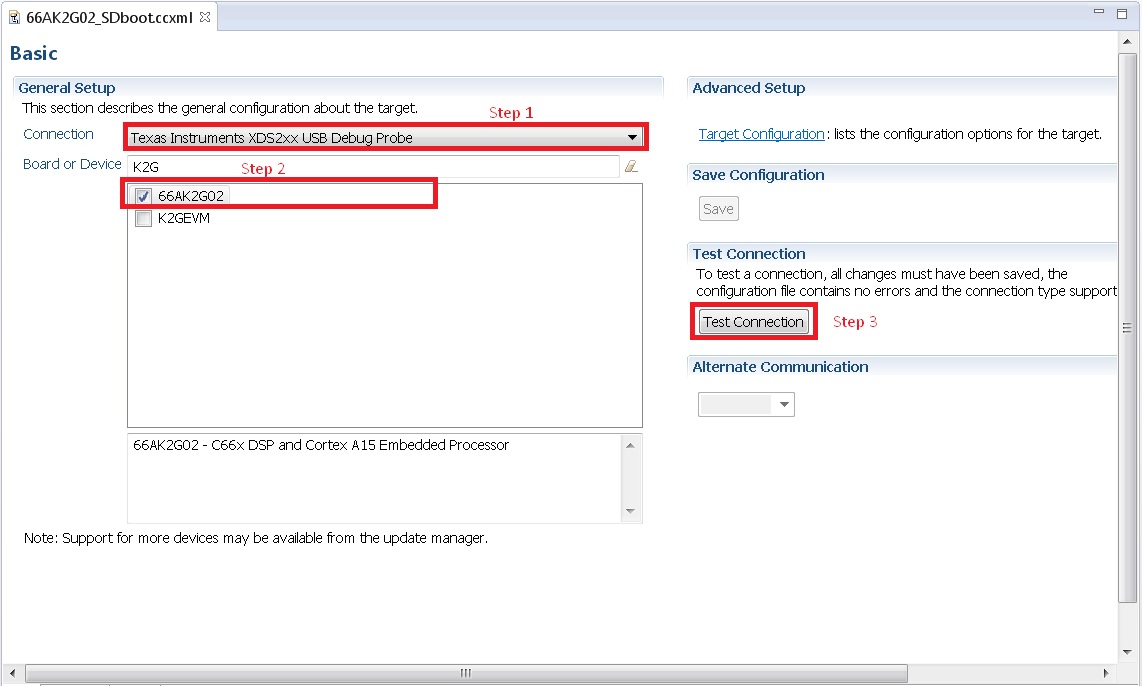
In advanced settings, make sure that no GEL files are populated.
2. 66AK2G02 GP EVM contains boot switches to configure for “SD/MMC boot” mode. So configure the boot switches to “SD/MMC Boot” as described in the section “Setting Boot Switches.”
3. Connect an XDS100 Emulator to the XDS USB port of the GP EVM as shown in the section “Connecting Emulator.”
4. Launch CCS and create a new target configuration as discussed in the previous section “Configuring target configuration files”.
5. Launch the newly created target configuration.
6. K2G will boot with ARM master boot from the SD card so connect to the A15_0. There will be no output on the console when you connect to the core.
7. SD card boot image will typically load a secondary bootloader like u-boot that will put the DSP in reset so users will need to follow the instructions in the guide How to take the C66x DSP out of reset with Linux running on A15
Note
RTOS users do not need to follow this step as the Secondary Bootloader (SBL) will put the DSP in idle state and not in reset if there is no code running on the DSP.