3.3.4.19. USB DWC3
Introduction
DWC3 is a SuperSpeed (SS) USB 3.0 Dual-Role-Device (DRD) from Synopsys.
Main features of DWC3:
The SuperSpeed USB controller features:
Dual-role device (DRD) capability:
Same programming model for SuperSpeed (SS), High-Speed (HS), Full-Speed (FS), and Low-Speed (LS)
Internal DMA controller
LPM protocol in USB 2.0 and U0, U1, U2, and U3 states for USB 3.0
TI SoC Integration
DWC3 is integrated in AM65x, OMAP5, DRA7x and AM437x SoCs from TI.
OMAP5 (omap5-uevm)
The following diagram depicts dwc3 integration in OMAP5. The ID and VBUS events are sensed by a companion device (palmas). The palmas-usb driver (drivers/extcon/extcon-palmas.c) notifies the events to OMAP glue driver (driver/usb/dwc3/dwc3-omap.c) via the extcon framework. The glue driver writes the events to the software mailbox present in DWC3 glue (SS USB OTG controller module in the diagram) which interrupts the core using UTMI+ signals.
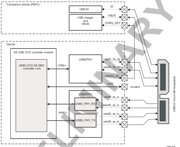
DRA7x/AM57x
The above diagram also depicts dwc3 integration in DRA7x/AM57x. Some boards provide VBUS and ID events over GPIO whereas some provide ID over GPIO and VBUS through Power Management IC (palmas).
DRA7-evm (J6-evm) and DRA72-evm (J6-eco) boards have ID detection but no VBUS detection support. ID detection is provided through GPIO expander (PCF8574).
DRA71-evm (J6entry-evm) board has VBUS and ID detection support. Both ID and VBUS detection are provided through GPIO expander (PCF8574).
On these boards, the GPIO driver (drivers/extcon/extcon-usb-gpio.c) notifies the ID and VBUS events to the OMAP dwc3 glue (drivers/usb/dwc3/dwc3-omap.c) via the extcon framework.
All DRA7x boards use USB1 port as Super-Speed dual-role port and USB2 port High-Speed Host port (Type mini-A). You will need a mini-A to Type-A adapter to use the Host port.
AM57x (BeagleBoard-x15/AM57xx-evm/AM57xx-IDK)
BeagleBoard-x15/AM57xx-evm use USB1 as Super-Speed host port and have a on-board Super-Speed hub which provides 3 Super-Speed Host (Type-A) ports. USB2 is used as High-Speed peripheral port. VBUS detection for USB2 port is provided through Power Management IC (palmas). The palmas USB driver (drivers/extcon/extcon-palmas.c) notifies the VBUS event to the OMAP dwc3 glue (drivers/usb/dwc3/dwc3-omap.c) via the extcon framework.
AM57xx-IDK boards use USB1 as a High-Speed Host port (Type-A) and USB2 as a High-Speed dual-role port. ID detection for USB2 is provided via GPIO whereas VBUS detection is provided through the PMIC (palmas). The palmas USB driver (drivers/extcon/extcon-palmas.c) notifies both VBUS and ID events to the OMAP dwc3 glue (drivers/usb/dwc3/dwc3-omap.c) via the extcon framework.
AM65x
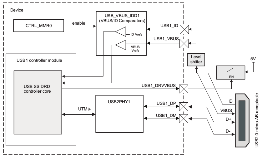
AM65x has 2 DWC3 controller instances. USB1 instance can be a super-speed port and USB2 instance is a high-speed port. The following diagram depicts dwc3 integration in AM65x’s high-speed port. VBUS and ID detection is done internally so companion device is not needed. DWC3 controller uses HW UTMI mode to get the VBUS and ID events and the glue driver (dwc3-am65.c) does not need to write to the software mailbox to notify the events to the dwc3 core.
On AM65x-evm/IDK, USB2 port is used as high-speed dual-role port (micro-AB) as shown in figure below.
Note
The board might come with force host jumper J4 pre-installed at the factory. Please remove this jumper for proper dual-role/device-mode operation of USB2 port.
On AM65x-IDK, USB1 port is available as a high-speed dual-role port (micro-AB) through a 2Lane PCIe USB2 SERDES card. See below figure.
Note
AM65x-IDK might come with the force host jumper J5 pre-installed on the SERDES card. Please remove this jumper for proper dual-role/device mode operation of USB1 port.
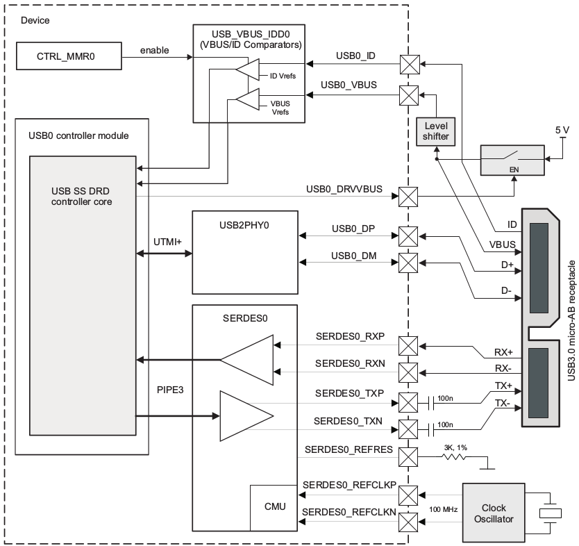
On AM65x-evm, USB1 port is available as a Super-Speed device or host port (3.0 micro-AB) through a 1Lane PCIe USB3 SERDES card. See below figure.
Note
AM65x-evm might come with the force host jumper J5 pre-installed on the SERDES card. Please remove this jumper for proper dual-role/device mode operation of USB1 port.
Features NOT supported
Full OTG is not supported. Only dual-role mode is supported.
Driver Configuration
The default kernel configuration enables support for USB_DWC3, USB_DWC3_OMAP (the wrapper driver), USB_DWC3_DUAL_ROLE.
The selection of DWC3 driver can be modified as follows: start Linux Kernel Configuration tool.
$ make menuconfig ARCH=arm
Select Device Drivers from the main menu.
...
Kernel Features  --->
Boot options  --->
CPU Power Management  --->
Floating point emulation  --->
Userspace binary formats  --->
Power management options  --->
[*] Networking support  --->
Device Drivers  --->
...
Select USB support from the menu.
...
Multimedia support  --->
Graphics support  --->
<M> Sound card support  --->
HID support  --->
[*] USB support  --->
< > Ultra Wideband devices  ----
<*> MMC/SD/SDIO card support  --->
...
Enable Host-side support and Gadget support
...
<M>   Support for Host-side USB
...
<M>   USB Gadget Support
...
Select DesignWare USB3 DRD Core Support and Texas Instruments OMAP5 and similar Platforms
...
<M>   DesignWare USB3 DRD Core Support
 DWC3 Mode Selection (Dual Role mode)  --->
 *** Platform Glue Driver Support ***
<M>     Texas Instruments OMAP5 and similar Platforms
...
Select Bus devices OMAP2SCP driver
...
-*- OMAP INTERCONNECT DRIVER
<*> OMAP OCP2SCP DRIVER
...
Select the PHY Subsystem for OMAP5, DRA7x and AM437x
...
[*] Reset Controller Support --->
< > FMC support ---->
PHY Subsystem  --->
...
Select the OMAP CONTRO PHY driver, OMAP USB2 PHY driver for OMAP5, DRA7 and AM437x
Select OMAP PIPE3 PHY driver for OMAP5 and DRA7x
...
-*- PHY Core
-*- OMAP CONTROL PHY Driver
<*> OMAP USB2 PHY Driver
<*> TI PIPE3 PHY Driver
...
Select ‘xHCI HCD (USB 3.0) SUPPORT’ from menuconfig in ‘USB support’
< >     Support WUSB Cable Based Association (CBA)
*** USB Host Controller Drivers ***
...
<*>     xHCI HCD (USB 3.0) support
...
Select ‘USB Gadget Support —>’ from menuconfig in ‘USB support’ and select the needed gadgets. (By default all gadgets are made as modules)
--- USB Gadget Support
[*]   Debugging messages (DEVELOPMENT)
[ ]     Verbose debugging Messages (DEVELOPMENT)
[*]   Debugging information files (DEVELOPMENT)
[*]   Debugging information files in debugfs (DEVELOPMENT)
(2)   Maximum VBUS Power usage (2-500 mA)
(2)   Number of storage pipeline buffers
USB Peripheral Controller  --->
<M>   USB Gadget Drivers
< >     USB functions configurable through configfs
<M>     Gadget Zero (DEVELOPMENT)
<M>     Audio Gadget
[ ]       UAC 1.0 (Legacy)
<M>     Ethernet Gadget (with CDC Ethernet support)
[*]       RNDIS support
[ ]       Ethernet Emulation Model (EEM) support
<M>     Network Control Model (NCM) support
<M>     Gadget Filesystem
<M>     Function Filesystem
[*]       Include configuration with CDC ECM (Ethernet)
[*]       Include configuration with RNDIS (Ethernet)
[*]       Include 'pure' configuration
<M>     Mass Storage Gadget
<M>     Serial Gadget (with CDC ACM and CDC OBEX support)
<M>     MIDI Gadget
<M>     Printer Gadget
<M>     CDC Composite Device (Ethernet and ACM)
<M>     CDC Composite Device (ACM and mass storage)
<M>     Multifunction Composite Gadget
[*]       RNDIS + CDC Serial + Storage configuration
[*]       CDC Ethernet + CDC Serial + Storage configuration
<M>     HID Gadget
<M>     HID Gadget
<M>     EHCI Debug Device Gadget
     EHCI Debug Device mode (serial)  --->
<M>     USB Webcam Gadget
Configuring DWC3 in gadget only
Configuring DWC3 in host only
Testing
Host Mode
Selecting cables
Example
Connecting a USB2.0 pendrive to the USB host port gives the following prints
[ 479.385084] usb 1-1: new high-speed USB device number 2 using xhci-hcd
[ 479.406841] usb 1-1: New USB device found, idVendor=054c, idProduct=05ba
[ 479.413911] usb 1-1: New USB device strings: Mfr=1, Product=2, SerialNumber=3
[ 479.422320] usb 1-1: Product: Storage Media
[ 479.426901] usb 1-1: Manufacturer: Sony
[ 479.430949] usb 1-1: SerialNumber: CB5001212140006303
[ 479.437774] usb 1-1: ep 0x81 - rounding interval to 128 microframes, ep desc says 255 microframes
[ 479.447454] usb 1-1: ep 0x2 - rounding interval to 128 microframes, ep desc says 255 microframes
[ 479.458124] usb-storage 1-1:1.0: USB Mass Storage device detected
[ 479.465355] scsi1 : usb-storage 1-1:1.0
[ 480.784475] scsi 1:0:0:0: Direct-Access Sony Storage Media 0100 PQ: 0 ANSI: 4
[ 480.801677] sd 1:0:0:0: [sda] 61046784 512-byte logical blocks: (31.2 GB/29.1 GiB)
[ 480.820740] sd 1:0:0:0: [sda] Write Protect is off
[ 480.825794] sd 1:0:0:0: [sda] Mode Sense: 43 00 00 00
[ 480.832797] sd 1:0:0:0: [sda] No Caching mode page found
[ 480.838574] sd 1:0:0:0: [sda] Assuming drive cache: write through
[ 480.852070] sd 1:0:0:0: [sda] No Caching mode page found
[ 480.857672] sd 1:0:0:0: [sda] Assuming drive cache: write through
[ 480.865873] sda: sda1
[ 480.874068] sd 1:0:0:0: [sda] No Caching mode page found
[ 480.879839] sd 1:0:0:0: [sda] Assuming drive cache: write through
[ 480.886434] sd 1:0:0:0: [sda] Attached SCSI removable disk
Device Mode
Mass Storage Gadget
In gadget mode standard USB cables with micro plug should be used.
Example: To use ramdisk as a backing store use the following
# mkdir /mnt/ramdrive
# mount -t tmpfs tmpfs /mnt/ramdrive -o size=600M
# dd if=/dev/zero of=/mnt/ramdrive/vfat-file bs=1M count=600
# mkfs.ext2 -F /mnt/ramdrive/vfat-file
# modprobe g_mass_storage file=/mnt/ramdrive/vfat-file
In order to see all other options supported by g_mass_storage, just run modinfo command:
# modinfo g_mass_storage
filename:       /lib/modules/3.17.0-rc6-00455-g0255b03-dirty/kernel/drivers/usb/gadget/legacy/g_mass_stor
age.ko
license:        GPL
author:         Michal Nazarewicz
description:    Mass Storage Gadget
srcversion:     3050477C3FFA3395C8D79CD
depends:        usb_f_mass_storage,libcomposite
intree:         Y
vermagic:       3.17.0-rc6-00455-g0255b03-dirty SMP mod_unload modversions ARMv6 p2v8
parm:           idVendor:USB Vendor ID (ushort)
parm:           idProduct:USB Product ID (ushort)
parm:           bcdDevice:USB Device version (BCD) (ushort)
parm:           iSerialNumber:SerialNumber string (charp)
parm:           iManufacturer:USB Manufacturer string (charp)
parm:           iProduct:USB Product string (charp)
parm:           file:names of backing files or devices (array of charp)
parm:           ro:true to force read-only (array of bool)
parm:           removable:true to simulate removable media (array of bool)
parm:           cdrom:true to simulate CD-ROM instead of disk (array of bool)
parm:           nofua:true to ignore SCSI WRITE(10,12) FUA bit (array of bool)
parm:           luns:number of LUNs (uint)
parm:           stall:false to prevent bulk stalls (bool)
Note: The USB Mass Storage Specification requires us to pass a valid iSerialNumber of 12 alphanumeric digits, however g_mass_storage will not generate one because the Kernel has no way of generating a stable and valid Serial Number. If you want to pass USB20CV and USB30CV MSC tests, pass a valid iSerialNumber argument.
USB 2.0 Test Modes
The Universal Serial Bus 2.0 Specification defines a set of Test Modes used to validate electrical quality of Data Lines pair (D+/D-). There are two ways of entering these Test Modes with DWC3.
Sending properly formatted SetFeature(TEST) Requests to the device (see USB2.0 spec for details)
This is the preferred (and Standard) way of entering USB 2.0 Test Modes. However, it’s not always that we will have a functioning USB Host to issue such requests.
Using a non-standard DebugFS interface (see below for details)
Any time we don’t have a functioning Host on the Test Setup and still want to enter USB 2.0 Test Modes, we can use this non-standard interface for that purpose. One such use-case is for low level USB 2.0 Eye Diagram testing where the DUT (Device Under Test) is connected to an oscilloscope through a test fixture.
Non-Standard DebugFS Interface
DWC3 Driver exposes a few testing and development tools through the Debug File System. In order to use it, you must first mount that file system in case it’s not mounted yet. Below, we show an example session on AM437x.
# mount -t debugfs none /sys/kernel/debug
# cd /sys/kernel/debug
# ls
48390000.usb  dri                 memblock  regulator       ubifs
483d0000.usb  extfrag             mmc0      sched_features  usb
asoc          fault_around_bytes  omap_mux  sleep_time      wakeup_sources
bdi           gpio                pinctrl   suspend_stats
clk           hid                 pm_debug  tracing
dma_buf       kprobes             regmap    ubi
Note the two directories terminated with .usb. Those are the two instances available on AM437x devices, 48390000.usb is USB1 and 483d0000.usb is USB2. Both of those directories contain the same thing, we will use 48390000.usb for the purposes of illustration.
# cd 48390000.usb
# ls
link_state  mode  regdump  testmode
link_state
Shows the current USB Link State
# cat link_state
U0
mode
Shows the current mode of operation. Available options are host, device, otg. It can also be used to dynamically change the mode by writing to this file any of the available options. Dynamically changing the mode of operation can be useful for debug purposes but this should never be used in production.
# cat mode
device
# echo host > mode
# cat mode
host
# echo device > mode
# cat mode
device
regdump
Shows a dump of all registers of DWC3 except for XHCI registers which are owned by the xhci-hcd driver.
# cat regdump
GSBUSCFG0 = 0x0000000e
GSBUSCFG1 = 0x00000f00
GTXTHRCFG = 0x00000000
GRXTHRCFG = 0x00000000
GCTL = 0x25802004
GEVTEN = 0x00000000
GSTS = 0x3e800002
GSNPSID = 0x5533240a
GGPIO = 0x00000000
GUID = 0x00031100
GUCTL = 0x02008010
GBUSERRADDR0 = 0x00000000
GBUSERRADDR1 = 0x00000000
GPRTBIMAP0 = 0x00000000
GPRTBIMAP1 = 0x00000000
GHWPARAMS0 = 0x402040ca
GHWPARAMS1 = 0x81e2493b
GHWPARAMS2 = 0x00000000
GHWPARAMS3 = 0x10420085
GHWPARAMS4 = 0x48a22004
GHWPARAMS5 = 0x04202088
GHWPARAMS6 = 0x08800c20
GHWPARAMS7 = 0x03401700
GDBGFIFOSPACE = 0x00420000
GDBGLTSSM = 0x01090460
GPRTBIMAP_HS0 = 0x00000000
GPRTBIMAP_HS1 = 0x00000000
GPRTBIMAP_FS0 = 0x00000000
GPRTBIMAP_FS1 = 0x00000000
GUSB2PHYCFG(0) = 0x00002500
GUSB2PHYCFG(1) = 0x00000000
GUSB2PHYCFG(2) = 0x00000000
GUSB2PHYCFG(3) = 0x00000000
GUSB2PHYCFG(4) = 0x00000000
GUSB2PHYCFG(5) = 0x00000000
GUSB2PHYCFG(6) = 0x00000000
GUSB2PHYCFG(7) = 0x00000000
GUSB2PHYCFG(8) = 0x00000000
GUSB2PHYCFG(9) = 0x00000000
GUSB2PHYCFG(10) = 0x00000000
GUSB2PHYCFG(11) = 0x00000000
GUSB2PHYCFG(12) = 0x00000000
GUSB2PHYCFG(13) = 0x00000000
GUSB2PHYCFG(14) = 0x00000000
GUSB2PHYCFG(15) = 0x00000000
GUSB2I2CCTL(0) = 0x00000000
GUSB2I2CCTL(1) = 0x00000000
GUSB2I2CCTL(2) = 0x00000000
GUSB2I2CCTL(3) = 0x00000000
GUSB2I2CCTL(4) = 0x00000000
GUSB2I2CCTL(5) = 0x00000000
GUSB2I2CCTL(6) = 0x00000000
GUSB2I2CCTL(7) = 0x00000000
GUSB2I2CCTL(8) = 0x00000000
GUSB2I2CCTL(9) = 0x00000000
GUSB2I2CCTL(10) = 0x00000000
...
A better use for this is, if you know the register name you’re looking for, by using grep we can reduce the amount of output. Assuming we want to check register DCTL we could:
# grep DCTL regdump
DCTL = 0x8c000000
testmode
Shows current USB 2.0 Test Mode. Can also be used to enter such test modes in situations where we can’t issue proper SetFeature(TEST) requests. Available options are test_j, test_k, test_se0_nak, test_packet, test_force_enable. The only way to exit the test modes is through a USB Reset.
# cat testmode
no test
# echo test_packet > testmode
# cat testmode
test_packet
Other Resources
For general Linux USB subsystem - Usbgeneralpage
USB Debugging - elinux.org/images/1/17/USB_Debugging_and_Profiling_Techniques.pdf