3.3.4.11. PCIe End Point
Introduction
PCIe controller IPs integrated in Jacinto are capable of operating either in Root Complex mode (host) or End Point mode (device). When operating in End Point (EP) mode, the controller can be configured to be used as any function depending on the use case (‘Test endpoint’ and ‘NTB’ are the only PCIe EP functions supported in Linux kernel right now).
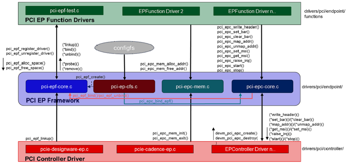
Block Diagram
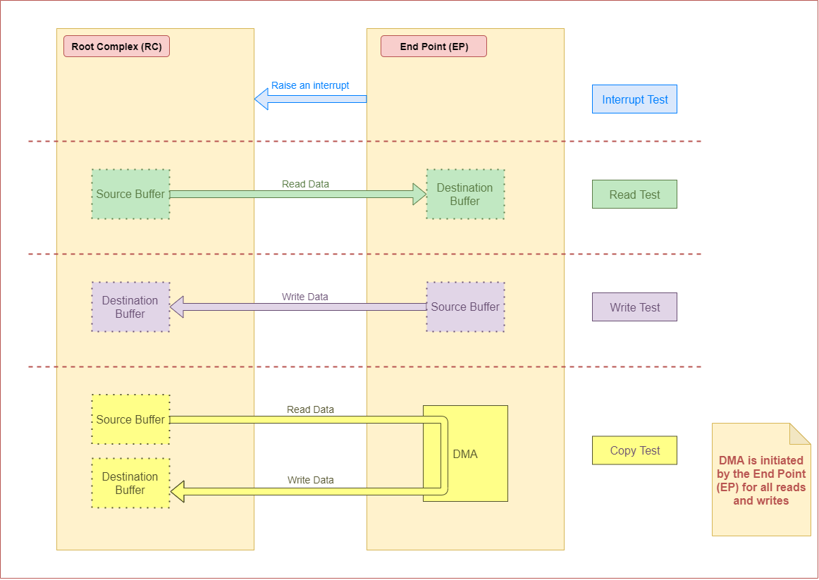
Following is the block diagram of framework for endpoint mode:
Features of J7ES
There are four instances of the PCIe subsystem. Following are some of the main features:
Each instance can be configured to operate in Root Complex mode or End Point mode
One or two lane configuration, capable up to 8.0 Gbps/lane (Gen3)
Single-root I/O Virtualization in End Point(EP) mode
6 Physical Functions (PF)
16 Virtual Functions (4 VF each for PF0, PF1, PF2 and PF3; 0 VF for PF4 and PF5)
Support for Legacy, MSI and MSI-X Interrupt
There can be 32 different address mappings in outbound address translation unit. The mappings can be from regions reserved for each PCIe instance.
For instance PCIE0 and PCIE1, there are two regions in SoC Memory Map:
128 MB region with address in lower 32 bits
4 GB region with address above 32 bits
For instance PCIE2 and PCIE3, there are two regions in SoC Memory Map:
128 MB region with address above 32 bits
4 GB region with address above 32 bits
Capabilities of J721E EVM
There are three instances of the PCIe subsystem on the EVM. Following are some of the details for each instance:
Instance |
Supported lanes |
Supported Connector |
|---|---|---|
PCIE0 |
1 lane |
Standard female connector |
PCIE1 |
2 lane |
Standard female connector |
PCIE2 |
2 lane |
m.2 connector keyed for SSD (M key) |
This wiki page provides usage information of PCIe EP Linux driver.
Hardware Setup Details
The following boards have a standard female connector.
dra74x-evm |
dra72x-evm |
am571x-idk |
am572x-idk |
k2g-gp-evm |
am654-evm |
am654-idk |
These boards are, by default, intended to be operated in Root Complex mode. So in order to connect two boards, a specialized cable like below is required.
AM65xx devices is, by default, intended to be operated in Root Complex mode. So in order to connect two boards, a specialized cable like below is required.
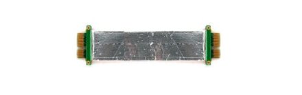
This cable can be obtained from Adex Electronics (https://www.adexelec.com).
Use either X1 cable or X4 cable depending on the slot provided in the board. The part number is PE-FLEX1-MM-CX-3” (for 3” cable length x1).
Modify the cable to remove resistors in CK+ and CK- in order to avoid ground loops (power) and smoking clock drivers (clk+/-).
Remove the RST resistors to avoid reset (PERST) being propagated from Root Complex to End Point. Also in Root Complex to End Point loopback connection, End Point running Linux should be initialized before Root Complex comes up. Propagating reset from Root Complex to End Point will do PORZ of End Point, which should be avoided.
The ends of the modified cable should look like below:
A side

B side
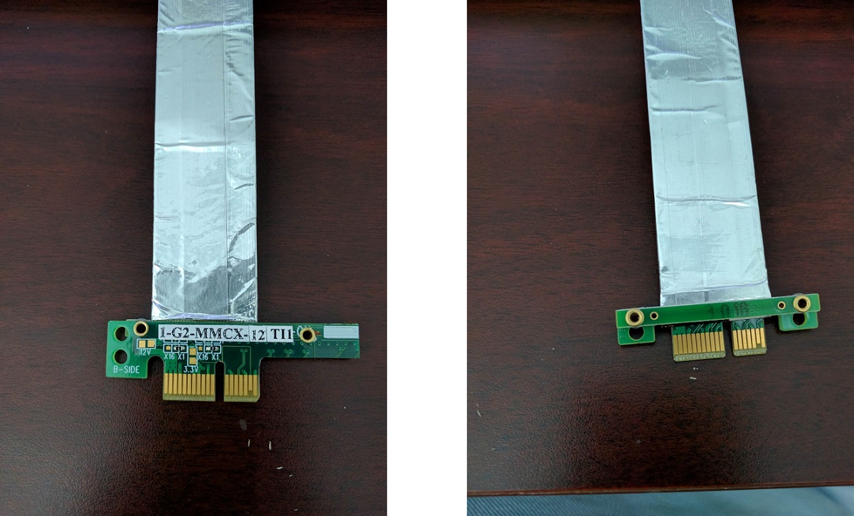
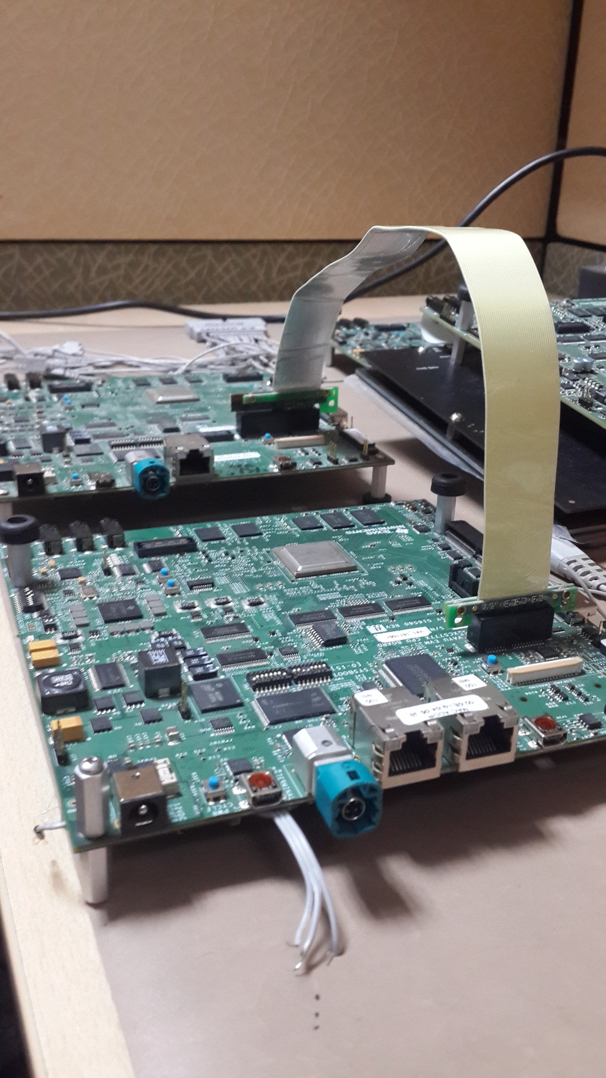
Image of a dra72-evm and dra7-evm connected back to back. There is no restriction on which end of the cable should be connected to host and device.
Note
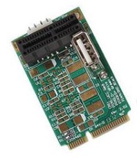
For AM572x GP EVM, there is a Mini PCIe connector on the LCD board. To connect 2 boards involving a AM572x GP EVM, a mPCIe-to-PCIe adapter is needed.
For AM65x boards, remove any jumpers present in the SERDES card when operating in endpoint mode.
Following is an image of two J721E EVMs connected back to back. There is no restriction on which end of the cable should be connected to host and device.
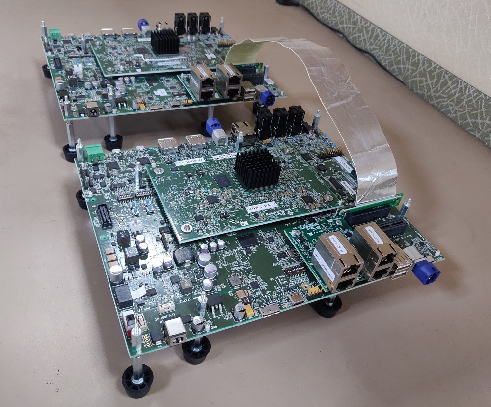
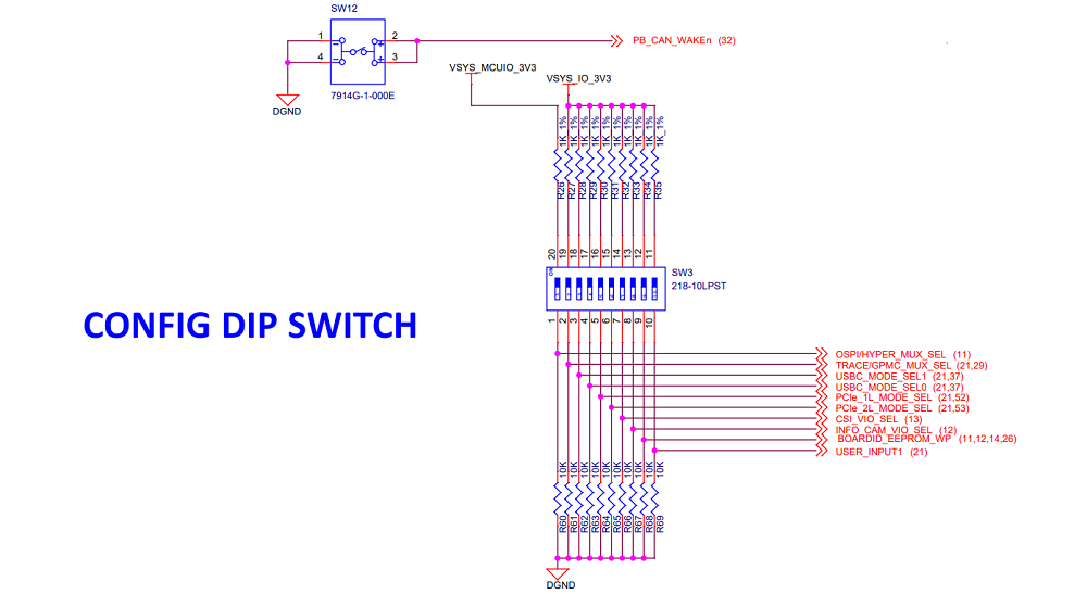
For End Point mode, PCIE_1L_MODE_SEL (switch 5) and PCIE_2L_MODE_SEL (switch 6) should be set to ‘1’.
End Point (EP) Device Configuration
DTS Modification
The default dts is configured to be used in root complex mode. In order to use it in endpoint mode, the following changes have to be made in dts file.
To configure dra7-evm in EP mode:
diff --git a/arch/arm/boot/dts/dra7-evm.dts b/arch/arm/boot/dts/dra7-evm.dts
index eedd930..93d9f17 100644
--- a/arch/arm/boot/dts/dra7-evm.dts
+++ b/arch/arm/boot/dts/dra7-evm.dts
@@ -1084,7 +1084,7 @@
        vdd-supply = <&smps7_reg>;
};

-&pcie1_rc {
+&pcie1_ep {
        status = "okay";
};
To configure dra72-evm in EP mode:
diff --git a/arch/arm/boot/dts/dra72-evm-common.dtsi b/arch/arm/boot/dts/dra72-evm-common.dtsi
index f914e6a..9697ea3 100644
--- a/arch/arm/boot/dts/dra72-evm-common.dtsi
+++ b/arch/arm/boot/dts/dra72-evm-common.dtsi
@@ -708,6 +708,6 @@
        watchdog-timers = <&timer10>;
};

-&pcie1_rc {
+&pcie1_ep {
        status = "okay";
};
To configure am572x-idk in EP mode:
diff --git a/arch/arm/boot/dts/am572x-idk.dts b/arch/arm/boot/dts/am572x-idk.dts
index b2edeab..1ef70b3 100644
--- a/arch/arm/boot/dts/am572x-idk.dts
+++ b/arch/arm/boot/dts/am572x-idk.dts
@@ -428,11 +428,11 @@
};

&pcie1_rc {
-       status = "okay";
        gpios = <&gpio3 23 GPIO_ACTIVE_HIGH>;
};

&pcie1_ep {
+       status = "okay";
        gpios = <&gpio3 23 GPIO_ACTIVE_HIGH>;
};
To configure am65x-evm in EP mode:
diff --git a/arch/arm64/boot/dts/ti/k3-am654-pcie-usb3.dtso b/arch/arm64/boot/dts/ti/k3-am654-pcie-usb3.dtso
index 3fc3c52aba80..789545d47e36 100644
--- a/arch/arm64/boot/dts/ti/k3-am654-pcie-usb3.dtso
+++ b/arch/arm64/boot/dts/ti/k3-am654-pcie-usb3.dtso
@@ -14,9 +14,8 @@
        status = "okay";
};

-&pcie1_rc {
+&pcie1_ep {
        phys = <&serdes1 PHY_TYPE_PCIE 0>;
        phy-names = "pcie-phy0";
-       reset-gpios = <&pca9555 5 GPIO_ACTIVE_HIGH>;
        status = "okay";
};
To configure am65x-idk in EP mode:
diff --git a/arch/arm64/boot/dts/ti/k3-am654-pcie-usb2.dtso b/arch/arm64/boot/dts/ti/k3-am654-pcie-usb2.dtso
index f5c15bbdf029..b259a86e9d20 100644
--- a/arch/arm64/boot/dts/ti/k3-am654-pcie-usb2.dtso
+++ b/arch/arm64/boot/dts/ti/k3-am654-pcie-usb2.dtso
@@ -46,10 +46,9 @@
        status = "okay";
};

-&pcie0_rc {
+&pcie0_ep {
        num-lanes = <2>;
        phys = <&serdes0 PHY_TYPE_PCIE 1>, <&serdes1 PHY_TYPE_PCIE 1>;
        phy-names = "pcie-phy0", "pcie-phy1";
-       reset-gpios = <&pca9555 5 GPIO_ACTIVE_HIGH>;
        status = "okay";
};
6.x SDK (4.19 Kernel)
To configure Beta J721E EVM in EP mode, apply the following patch:
diff --git a/arch/arm64/boot/dts/ti/k3-j721e-common-proc-board.dts b/arch/arm64/boot/dts/ti/k3-j721e-common-proc-board.dts
index 57d72aa945b7..3384dd6063c2 100644
--- a/arch/arm64/boot/dts/ti/k3-j721e-common-proc-board.dts
+++ b/arch/arm64/boot/dts/ti/k3-j721e-common-proc-board.dts
@@ -734,7 +734,7 @@
};

&pcie0 {
-       pci-mode = <PCI_MODE_RC>;
+       pci-mode = <PCI_MODE_EP>;
        num-lanes = <1>;
};

@@ -754,6 +754,11 @@
        phy-names = "pcie_phy";
};

+&pcie0_ep {
+       phys = <&serdes0_pcie_link>;
+       phy-names = "pcie_phy";
+};
+
&pcie1_rc {
        reset-gpios = <&exp1 2 GPIO_ACTIVE_HIGH>;
        phys = <&serdes1_pcie_link>;
To configure Alpha J721E EVM in EP mode, apply the following patch:
diff --git a/arch/arm64/boot/dts/ti/k3-j721e-proc-board-tps65917.dts b/arch/arm64/boot/dts/ti/k3-j721e-proc-board-tps65917.dts
index b9fece8d267c..d50f764c6642 100644
--- a/arch/arm64/boot/dts/ti/k3-j721e-proc-board-tps65917.dts
+++ b/arch/arm64/boot/dts/ti/k3-j721e-proc-board-tps65917.dts
@@ -769,7 +769,7 @@
};

&pcie0 {
-       pci-mode = <PCI_MODE_RC>;
+       pci-mode = <PCI_MODE_EP>;
        num-lanes = <1>;
};

@@ -789,6 +789,11 @@
        phy-names = "pcie_phy";
};

+&pcie0_ep {
+       phys = <&serdes0_pcie_link>;
+       phy-names = "pcie_phy";
+};
+
&pcie1_rc {
        reset-gpios = <&exp1 2 GPIO_ACTIVE_HIGH>;
        phys = <&serdes1_pcie_link>;
7.x SDK (5.4 Kernel)
To configure J721E EVM in EP mode, apply the following patch:
diff --git a/arch/arm64/boot/dts/ti/k3-j721e-common-proc-board.dts b/arch/arm64/boot/dts/ti/k3-j721e-common-proc-board.dts
index 6788a3611..b7cd6c7b6 100644
--- a/arch/arm64/boot/dts/ti/k3-j721e-common-proc-board.dts
+++ b/arch/arm64/boot/dts/ti/k3-j721e-common-proc-board.dts
@@ -813,6 +813,7 @@
        phys = <&serdes0_pcie_link>;
        phy-names = "pcie_phy";
        num-lanes = <1>;
+       status = "disabled";
 }; &pcie1_rc {
@@ -833,7 +834,6 @@
        phys = <&serdes0_pcie_link>;
        phy-names = "pcie_phy";
        num-lanes = <1>;
-       status = "disabled";
 }; &pcie1_ep {
Linux Driver Configuration
The following config options have to be enabled in order to configure the PCI controller to be used as a “Endpoint Test” function driver.
CONFIG_PCI_ENDPOINT=y
CONFIG_PCI_EPF_TEST=y
CONFIG_PCI_DRA7XX_EP=y
CONFIG_PCI_ENDPOINT=y
CONFIG_PCI_ENDPOINT_CONFIGFS=y
CONFIG_PCI_EPF_TEST=y
CONFIG_PCI_J721E=y
CONFIG_PCIE_CADENCE_EP=y
Endpoint Controller devices and Function drivers
To find the list of endpoint controller devices in the system:
# ls /sys/class/pci_epc/
51000000.pcie_ep
root@j7-evm:~# ls /sys/class/pci_epc/
2900000.pcie-ep
To find the list of endpoint function drivers in the system:
# ls /sys/bus/pci-epf/drivers
pci_epf_test
root@j7-evm:~# ls /sys/bus/pci-epf/drivers
pci_epf_test  pci_epf_ntb
Using the pci-epf-test function driver
The pci-epf-test function driver can be used to test the endpoint functionality of the PCI controller. Some of the tests that are currently supported are:
Test |
Description |
|---|---|
BAR |
A known pattern is written and read back from BAR |
Interrupt (legacy/MSI/MSI-X) |
Raise an interrupt (legacy/MSI/MSI-X) from EP |
Read |
Read data from a buffer in RC, and perform a cyclic redundancy check (CRC) for that data |
Write |
Write data to a buffer in RC, and perform a cyclic redundancy check (CRC) for that data |
Copy |
Copy data from one RC buffer to another RC buffer, and perform a cyclic redundancy check (CRC) for that data |
4.4 Kernel
Creating pci-epf-test device
PCI endpoint function device can be created using the configfs. To create pci-epf-test device, the following commands can be used:
# mount -t configfs none /sys/kernel/config
# cd /sys/kernel/config/pci_ep/
# mkdir pci_epf_test.0
The “mkdir pci_epf_test.0” above creates the pci-epf-test function device. The name given to the directory preceding ‘.’ should match with the name of the driver listed in ‘/sys/bus/pci-epf/drivers’ in order for the device to be bound to the driver.
The PCI endpoint framework populates the directory with configurable fields.
# cd pci_epf_test.0
# ls
  baseclass_code    function    revid      vendorid
  cache_line_size   interrupt_pin   subclass_code
  deviceid             peripheral   subsys_id
  epc               progif_code subsys_vendor_id
The driver populates these entries with default values when the device is bound to the driver. The pci-epf-test driver populates vendorid with 0xffff and interrupt_pin with 0x0001.
# cat vendorid
  0xffff
# cat interrupt_pin
  0x0001
Configuring pci-epf-test device
The user can configure the pci-epf-test device using the configfs. In order to change the vendorid and the number of MSI interrupts used by the function device, the following commands can be used:
# echo 0x104c > vendorid
# echo 16 >  msi_interrupts
Binding pci-epf-test device to a EP controller
In order for the endpoint function device to be useful, it has to be bound to a PCI endpoint controller driver. Use the configfs to bind the function device to one of the controller drivers present in the system.
# echo "51000000.pcie_ep" > epc
Once the above step is completed, the PCI endpoint is ready to establish a link with the host.
4.9 Kernel
Creating pci-epf-test device
PCI endpoint function device can be created using the configfs. To create pci-epf-test device, the following commands can be used:
# mount -t configfs none /sys/kernel/config
# cd /sys/kernel/config/pci_ep/
# mkdir dev
# mkdir dev/epf/pci_epf_test.0
The “mkdir dev/epf/pci_epf_test.0” above creates the pci-epf-test function device. The name given to the directory preceding ‘.’ should match with the name of the driver listed in ‘/sys/bus/pci-epf/drivers’ in order for the device to be bound to the driver.
The PCI endpoint framework populates the directory with configurable fields.
# ls dev/epf/pci_epf_test.0/
  baseclass_code    function    revid      vendorid
  cache_line_size   interrupt_pin   subclass_code
  deviceid             peripheral   subsys_id
  epc               progif_code subsys_vendor_id
The driver populates these entries with default values when the device is bound to the driver. The pci-epf-test driver populates vendorid with 0xffff and interrupt_pin with 0x0001.
# cat dev/epf/pci_epf_test.0/vendorid
  0xffff
# cat dev/epf/pci_epf_test.0/interrupt_pin
  0x0001
Configuring pci-epf-test device
The user can configure the pci-epf-test device using the configfs. In order to change the vendorid and the number of MSI interrupts used by the function device, the following commands can be used:
# echo 0x104c > dev/epf/pci_epf_test.0/vendorid
The above command configures Texas Instruments as the vendor.
If the endpoint is a DRA74x or AM572x device:
# echo 0xb500 > dev/epf/pci_epf_test.0/deviceid
If the endpoint is a DRA72x or AM572x device:
# echo 0xb501 > dev/epf/pci_epf_test.0/deviceid
The above command configures the deviceid.
# echo 16 > dev/epf/pci_epf_test.0/msi_interrupts
The above command configures the number of interrupts. 16 is the number of interrupts being configured. The number of interrupts configured should be between 1 to 32 for MSI.
Binding pci-epf-test device to a EP controller
In order for the endpoint function device to be useful, it has to be bound to a PCI endpoint controller driver. Use the configfs to bind the function device to one of the controller drivers present in the system.
# echo "51000000.pcie_ep" > dev/epc
Once the above step is completed, the PCI endpoint is ready to establish a link with the host.
4.14 Kernel
The following steps should be followed for the upstreamed solution (from 4.12 kernel). The custom solution used in 4.9/4.4 should not be used for upstreamed solution.
Creating pci-epf-test device
PCI endpoint function device can be created using the configfs. To create pci-epf-test device, the following commands can be used:
# mount -t configfs none /sys/kernel/config
# cd /sys/kernel/config/pci_ep/
In the case of dra7x/am57x, use the below command to create pci-epf-test function device.
# mkdir functions/pci_epf_test/func1
In the case of k2g, use the below command to create pci-epf-test function device.
# mkdir functions/pci_epf_test_k2g/func1
In the case of am65x, use the below command to create pci-epf-test function device.
# mkdir functions/pci_epf_test_am6/func1
The PCI endpoint framework populates the directory with configurable fields.
All the commands below use pci_epf_test. However depending on the platform pci_epf_test or pci_epf_test_k2g or pci_epf_test_am6 should be used.
# ls functions/pci_epf_test/func1
  baseclass_code    function    revid      vendorid
  cache_line_size   interrupt_pin   subclass_code
  deviceid             peripheral   subsys_id
  epc               progif_code subsys_vendor_id
The driver populates these entries with default values when the device is bound to the driver. The pci-epf-test driver populates vendorid with 0xffff and interrupt_pin with 0x0001.
# cat functions/pci_epf_test/func1/vendorid
  0xffff
# cat functions/pci_epf_test/func1/interrupt_pin
  0x0001
Configuring pci-epf-test device
The user can configure the pci-epf-test device using the configfs. In order to change the vendorid and the number of MSI interrupts used by the function device, the following commands can be used:
# echo 0x104c > functions/pci_epf_test/func1/vendorid
The above command configures Texas Instruments as the vendor.
If the endpoint is a DRA74x or AM572x device:
# echo 0xb500 > functions/pci_epf_test/func1/deviceid
If the endpoint is a DRA72x or AM572x device:
# echo 0xb501 > functions/pci_epf_test/func1/deviceid
If the endpoint is K2G device:
# echo 0xb00b > functions/pci_epf_test_k2g/func1/deviceid
If the endpoint is AM6 device:
# echo 0xb00c > functions/pci_epf_test_am6/func1/deviceid
The above command configures the deviceid.
# echo 16 > functions/pci_epf_test/func1/msi_interrupts
The above command configures the number of interrupts. 16 is the number of interrupts being configured. The number of interrupts configured should be between 1 to 32 for MSI.
Binding pci-epf-test device to a EP controller
In order for the endpoint function device to be useful, it has to be bound to a PCI endpoint controller driver. Use the configfs to bind the function device to one of the controller drivers present in the system.
If the endpoint is a DRA72x or AM572x device:
# ln -s functions/pci_epf_test/func1 controllers/51000000.pcie_ep/
If the endpoint is a K2G device:
# ln -s functions/pci_epf_test_k2g/func1 controllers/21800000.pcie-ep/
If the endpoint is a AM654-EVM device:
# ln -s functions/pci_epf_test_am6/func1 controllers/5600000.pcie-ep
If the endpoint is a AM654-IDK device:
# ln -s functions/pci_epf_test_am6/func1 controllers/5500000.pcie-ep
Starting the EP device
In order for the EP device to be ready to establish the link, the following command should be given.
If the endpoint is a DRA72x or AM572x device:
# echo 1 > controllers/51000000.pcie_ep/start
If the endpoint is a K2G device:
# echo 1 > controllers/21800000.pcie-ep/start
If the endpoint is a AM654-EVM device:
# echo 1 > controllers/5600000.pcie-ep/start
If the endpoint is a AM654-IDK device:
# echo 1 > controllers/5500000.pcie-ep/start
Once the above step is completed, the PCI endpoint is ready to establish a link with the host.
K2G Limitation
K2G outbound transfers has a limitation that the target address should be aligned to a minimum of 1MB address. This restriction is because of PCIE_OB_OFFSET_INDEXn where BITS 1 to 19 is reserved. (Please note 1MB is minimum alignment and it can be changed to 1MB/2MB/4MB/8MB by specifying it in PCIE_OB_SIZE register).
Outbound transfers are used by PCI endpoint to access RC’s memory and for raising MSI interrupts. So with 1MB restriction both RC memory and MSI interrupts will be impacted since standard linux API’s like dma_alloc_coherent, get_free_pages etc.. doesn’t give 1MB aligned memory. While custom driver can be created to get 1MB aligned memory for accessing RC’s memory, MSI memory is allocated by RC controller driver and there is no way to tell it to give 1MB aligned address.
These restrictions are not specified in PCI standard and is bound to cause issues for 66AK2G users.
Creating pci-epf-test device
PCI endpoint function device can be created using the configfs. To create pci-epf-test function, the following commands can be used:
mount -t configfs none /sys/kernel/config
cd /sys/kernel/config/pci_ep/
mkdir functions/pci_epf_test/func1
The above commands create the pci-epf-test function device.
The PCI endpoint framework populates the directory with configurable fields.
root@j7-evm:/sys/kernel/config/pci_ep# ls functions/pci_epf_test/func1
baseclass_code  cache_line_size  deviceid  interrupt_pin  msi_interrupts  msix_interrupts  progif_code  revid  subclass_code  subsys_id  subsys_vendor_id  vendorid
The driver populates these entries with default values when the device is bound to the driver. The pci-epf-test driver populates vendorid with 0xffff and interrupt_pin with 0x0001.
root@j7-evm:/sys/kernel/config/pci_ep# cat functions/pci_epf_test/func1/vendorid
0xffff
root@j7-evm:/sys/kernel/config/pci_ep# cat functions/pci_epf_test/func1/interrupt_pin
0x0001
Configuring pci-epf-test device
The user can configure the pci-epf-test device using the configfs. In order to change the vendorid and the number of MSI interrupts used by the function device, the following commands can be used:
root@j7-evm:/sys/kernel/config/pci_ep# echo 0x104c > functions/pci_epf_test/func1/vendorid
The above command configures Texas Instruments as the vendor.
root@j7-evm:/sys/kernel/config/pci_ep# echo 0xb00d > functions/pci_epf_test/func1/deviceid
The above command configures the deviceid.
root@j7-evm:/sys/kernel/config/pci_ep# echo 2 > functions/pci_epf_test/func1/msi_interrupts
root@j7-evm:/sys/kernel/config/pci_ep# echo 2 > functions/pci_epf_test/func1/msix_interrupts
The above command configures the number of interrupts. 2 is the number of MSI and MSI-X interrupts being configured. The number of interrupts configured should be between 1 to 32 for MSI and 1 to 2048 for MSI-X.
Binding pci-epf-test device to a EP controller
In order for the endpoint function device to be useful, it has to be bound to a PCI endpoint controller driver. Use the configfs to bind the function device to one of the controller drivers present in the system.
root@j7-evm:/sys/kernel/config/pci_ep# ln -s functions/pci_epf_test/func1 controllers/2900000.pcie-ep/
Starting the EP device
In order for the EP device to be ready to establish the link, the following command should be given:
root@j7-evm:/sys/kernel/config/pci_ep# echo 1 > controllers/2900000.pcie-ep/start
The complete sequence when using six physical functions, will look like the following:
mount -t configfs none /sys/kernel/config
cd /sys/kernel/config/pci_ep/
mkdir functions/pci_epf_test/func1
echo 0x104c > functions/pci_epf_test/func1/vendorid
echo 0xb00d > functions/pci_epf_test/func1/deviceid
echo 2 > functions/pci_epf_test/func1/msi_interrupts
echo 2 > functions/pci_epf_test/func1/msix_interrupts
ln -s functions/pci_epf_test/func1 controllers/2900000.pcie-ep/

mkdir functions/pci_epf_test/func2
echo 0x104c > functions/pci_epf_test/func2/vendorid
echo 0xb00d > functions/pci_epf_test/func2/deviceid
echo 2 > functions/pci_epf_test/func2/msi_interrupts
echo 2 > functions/pci_epf_test/func2/msix_interrupts
ln -s functions/pci_epf_test/func2 controllers/2900000.pcie-ep/

mkdir functions/pci_epf_test/func3
echo 0x104c > functions/pci_epf_test/func3/vendorid
echo 0xb00d > functions/pci_epf_test/func3/deviceid
echo 2 > functions/pci_epf_test/func3/msi_interrupts
echo 2 > functions/pci_epf_test/func3/msix_interrupts
ln -s functions/pci_epf_test/func3 controllers/2900000.pcie-ep/

mkdir functions/pci_epf_test/func4
echo 0x104c > functions/pci_epf_test/func4/vendorid
echo 0xb00d > functions/pci_epf_test/func4/deviceid
echo 2 > functions/pci_epf_test/func4/msi_interrupts
echo 2 > functions/pci_epf_test/func4/msix_interrupts
ln -s functions/pci_epf_test/func4 controllers/2900000.pcie-ep/

mkdir functions/pci_epf_test/func5
echo 0x104c > functions/pci_epf_test/func5/vendorid
echo 0xb00d > functions/pci_epf_test/func5/deviceid
echo 2 > functions/pci_epf_test/func5/msi_interrupts
echo 2 > functions/pci_epf_test/func5/msix_interrupts
ln -s functions/pci_epf_test/func5 controllers/2900000.pcie-ep/

mkdir functions/pci_epf_test/func6
echo 0x104c > functions/pci_epf_test/func6/vendorid
echo 0xb00d > functions/pci_epf_test/func6/deviceid
echo 2 > functions/pci_epf_test/func6/msi_interrupts
echo 2 > functions/pci_epf_test/func6/msix_interrupts
ln -s functions/pci_epf_test/func6 controllers/2900000.pcie-ep/
echo 1 > controllers/2900000.pcie-ep/start
If you want to use the virtual functions, you need to bind it to a physical function. And the physical function needs to be bound to a controller.
A sample sequence of commands for using the virtual functions is as follows:
mount -t configfs none /sys/kernel/config
cd /sys/kernel/config/pci_ep/
mkdir functions/pci_epf_test/vf1
echo 0x104c > functions/pci_epf_test/vf1/vendorid
echo 0xb00d > functions/pci_epf_test/vf1/deviceid
echo 4 > functions/pci_epf_test/vf1/msi_interrupts
echo 8 > functions/pci_epf_test/vf1/msix_interrupts

mkdir functions/pci_epf_test/vf2
echo 0x104c > functions/pci_epf_test/vf2/vendorid
echo 0xb00d > functions/pci_epf_test/vf2/deviceid
echo 4 > functions/pci_epf_test/vf2/msi_interrupts
echo 8 > functions/pci_epf_test/vf2/msix_interrupts

mkdir functions/pci_epf_test/pf1
echo 0x104c > functions/pci_epf_test/pf1/vendorid
echo 0xb00d > functions/pci_epf_test/pf1/deviceid
echo 16 > functions/pci_epf_test/pf1/msi_interrupts
echo 16 > functions/pci_epf_test/pf1/msix_interrupts

ln -s functions/pci_epf_test/vf1 functions/pci_epf_test/pf1
ln -s functions/pci_epf_test/vf2 functions/pci_epf_test/pf1
ln -s functions/pci_epf_test/pf1 controllers/2910000.pcie-ep

echo 1 > controllers/2910000.pcie-ep/start
HOST Device Configuration
The PCI EP device must be powered-on and configured before the PCI HOST device. This restriction is because the PCI HOST doesn’t have hot plug support.
Linux Driver Configuration
The following config options have to be enabled in order to use the “Endpoint Test” PCI device.
CONFIG_PCI=y
CONFIG_PCI_ENDPOINT_TEST=y
CONFIG_PCI_DRA7XX_HOST=y
CONFIG_PCI=y
CONFIG_PCI_ENDPOINT_TEST=y
CONFIG_PCIE_CADENCE_HOST=y
lspci output
00:00.0 PCI bridge: Texas Instruments Device 8888 (rev 01)
01:00.0 Unassigned class [ff00]: Texas Instruments Device b500
0000:00:00.0 PCI bridge: Texas Instruments Device b00d
0000:01:00.0 Unassigned class [ff00]: Texas Instruments Device b00d
0000:01:00.1 Unassigned class [ff00]: Texas Instruments Device b00d
0000:01:00.2 Unassigned class [ff00]: Texas Instruments Device b00d
0000:01:00.3 Unassigned class [ff00]: Texas Instruments Device b00d
0000:01:00.4 Unassigned class [ff00]: Texas Instruments Device b00d
0000:01:00.5 Unassigned class [ff00]: Texas Instruments Device b00d
0001:00:00.0 PCI bridge: Texas Instruments Device b00d
0002:00:00.0 PCI bridge: Texas Instruments Device b00d
Using the Endpoint Test function device
pci_endpoint_test driver creates the Endpoint Test function device (/dev/pci-endpoint-test.0) which will be used by the following pcitest utility. pci_endpoint_test can either be built-in to the kernel or built as a module. For testing legacy interrupt, MSI interrupt has to be disabled in the host.
In order to not enable MSI (for testing legacy interrupt in DRA7)
insmod pci_endpoint_test.ko no_msi=1
Please note MSI interrupt by default is not enabled for K2G.
pcitest.sh added in tools/pci/ can be used to run all the default PCI endpoint tests. Before pcitest.sh can be used, pcitest.c should be compiled using
cd <kernel-dir>
make headers_install ARCH=arm
arm-linux-gnueabihf-gcc -Iusr/include tools/pci/pcitest.c -o pcitest
cp pcitest  <rootfs>/usr/sbin/
cp tools/pci/pcitest.sh <rootfs>
pcitest.sh output
root@dra7xx-evm:~# ./pcitest.sh
BAR tests
BAR0:           OKAY
BAR1:           OKAY
BAR2:           OKAY
BAR3:           OKAY
BAR4:           NOT OKAY
BAR5:           NOT OKAY

Interrupt tests

LEGACY IRQ:     NOT OKAY
MSI1:           OKAY
MSI2:           OKAY
MSI3:           OKAY
MSI4:           OKAY
MSI5:           OKAY
MSI6:           OKAY
MSI7:           OKAY
MSI8:           OKAY
MSI9:           OKAY
MSI10:          OKAY
MSI11:          OKAY
MSI12:          OKAY
MSI13:          OKAY
MSI14:          OKAY
MSI15:          OKAY
MSI16:          OKAY
MSI17:          NOT OKAY
MSI18:          NOT OKAY
MSI19:          NOT OKAY
MSI20:          NOT OKAY
MSI21:          NOT OKAY
MSI22:          NOT OKAY
MSI23:          NOT OKAY
MSI24:          NOT OKAY
MSI25:          NOT OKAY
MSI26:          NOT OKAY
MSI27:          NOT OKAY
MSI28:          NOT OKAY
MSI29:          NOT OKAY
MSI30:          NOT OKAY
MSI31:          NOT OKAY
MSI32:          NOT OKAY

Read Tests

READ (      1 bytes):           OKAY
READ (   1024 bytes):           OKAY
READ (   1025 bytes):           OKAY
READ (1024000 bytes):           OKAY
READ (1024001 bytes):           OKAY

Write Tests

WRITE (      1 bytes):          OKAY
WRITE (   1024 bytes):          OKAY
WRITE (   1025 bytes):          OKAY
WRITE (1024000 bytes):          OKAY
WRITE (1024001 bytes):          OKAY

Copy Tests

COPY (      1 bytes):           OKAY
COPY (   1024 bytes):           OKAY
COPY (   1025 bytes):           OKAY
COPY (1024000 bytes):           OKAY
COPY (1024001 bytes):           OKAY
pci_endpoint_test driver creates the Endpoint Test function device which will be used by the following pcitest utility. pci_endpoint_test can either be built-in to the kernel or built as a module. For testing legacy interrupt, MSI interrupt has to be disabled in the host.
pcitest.sh added in tools/pci/ can be used to run all the default PCI endpoint tests. Before pcitest.sh can be used, pcitest.c should be compiled using following steps:
cd <kernel-dir>
make headers_install ARCH=arm64
aarch64-linux-gnu-gcc -Iusr/include tools/pci/pcitest.c -o pcitest
cp pcitest  <rootfs>/usr/sbin/
cp tools/pci/pcitest.sh <rootfs>
pcitest output
pcitest can be used as follows:
root@j7-evm:~# ./pcitest -h
usage:  -h                      Print this help message
[options]
Options:
        -D <dev>                PCI endpoint test device {default: /dev/pci-endpoint-test.0}
        -b <bar num>            BAR test (bar number between 0..5)
        -m <msi num>            MSI test (msi number between 1..32)
        -x <msix num>           MSI-X test (msix number between 1..2048)
        -i <irq type>           Set IRQ type (0 - Legacy, 1 - MSI, 2 - MSI-X)
        -e                      Clear IRQ
        -I                      Get current IRQ type configured
        -l                      Legacy IRQ test
        -r                      Read buffer test
        -w                      Write buffer test
        -c                      Copy buffer test
        -s <size>               Size of buffer {default: 100KB}
Sample usage
root@j7-evm:~# ./pcitest -i 1 -D /dev/pci-endpoint-test.0
SET IRQ TYPE TO MSI:            OKAY
root@j7-evm:~# ./pcitest -m 1 -D /dev/pci-endpoint-test.0
MSI1:           OKAY
root@j7-evm:~# ./pcitest -e -D /dev/pci-endpoint-test.0
CLEAR IRQ:              OKAY
root@j7-evm:~# ./pcitest -i 2 -D /dev/pci-endpoint-test.0
SET IRQ TYPE TO MSI-X:          OKAY
root@j7-evm:~# ./pcitest -x 1 -D /dev/pci-endpoint-test.0
MSI-X1:         OKAY
root@j7-evm:~# ./pcitest -e -D /dev/pci-endpoint-test.0
CLEAR IRQ:              OKAY
The script pcitest.sh runs all the bar tests, interrupt tests, read tests, write tests and copy tests.
Files
Serial No |
Location |
Description |
|---|---|---|
1 |
drivers/pci/endpoint/pci-epc-core.c |
PCI Endpoint Framework |
drivers/pci/endpoint/pci-ep-cfs.c |
||
drivers/pci/endpoint/pci-epc-mem.c |
||
drivers/pci/endpoint/pci-epf-core.c |
||
2 |
drivers/pci/endpoint/functions/pci-epf-test.c |
PCI Endpoint Function Driver |
3 |
drivers/misc/pci_endpoint_test.c |
PCI Driver |
4 |
tools/pci/pcitest.c |
PCI Userspace Tools |
tools/pci/pcitest.sh |
||
5 |
4.4 Kernel |
PCI Controller Driver |
drivers/pci/controller/pci-dra7xx.c |
||
drivers/pci/controller/pcie-designware.c |
||
drivers/pci/controller/pcie-designware-ep.c |
||
drivers/pci/controller/pcie-designware-host.c |
||
4.4 Kernel |
||
drivers/pci/dwc/pci-dra7xx.c |
||
drivers/pci/dwc/pcie-designware.c |
||
drivers/pci/dwc/pcie-designware-ep.c |
||
drivers/pci/dwc/pcie-designware-host.c |
Serial No |
Location |
Description |
|---|---|---|
1 |
drivers/pci/endpoint/pci-epc-core.c |
PCI Endpoint Framework |
drivers/pci/endpoint/pci-ep-cfs.c |
||
drivers/pci/endpoint/pci-epc-mem.c |
||
drivers/pci/endpoint/pci-epf-core.c |
||
2 |
drivers/pci/endpoint/functions/pci-epf-test.c |
PCI Endpoint Function Driver |
3 |
drivers/misc/pci_endpoint_test.c |
PCI Driver |
4 |
tools/pci/pcitest.c |
PCI Userspace Tools |
tools/pci/pcitest.sh |
||
5 |
drivers/pci/controller/pci-j721e.c |
PCI Controller Driver |
drivers/pci/controller/pcie-cadence.c |
||
drivers/pci/controller/pcie-cadence-ep.c |
||
drivers/pci/endpoint/pcie-cadence-host.c |
J7200 Testing Details
PCIe and QSGMII uses the same SERDES in J7200. The default SDK is enabled for QSGMII. In order to test PCIe, Ethfw firmware shouldn’t be loaded and PCIe overlay file should be applied.
The simplest way to avoid ethfw from being loaded is to link j7200-main-r5f0_0-fw to IPC firmware.
root@j7200-evm:~# rm /lib/firmware/j7200-main-r5f0_0-fw
root@j7200-evm:~# ln -s /lib/firmware/pdk-ipc/ipc_echo_test_mcu2_0_release_strip.xer5f /lib/firmware/j7200-main-r5f0_0-fw
The following two Device Tree Overlay should be applied for testing J7200 EP.
The following command should be given in u-boot to apply overlay
=> setenv name_overlays k3-j7200-common-proc-board-pcie.dtbo k3-j7200-common-proc-board-pcie-ep.dtso