3.3.4.3. CAL
3.3.4.3.1. Introduction
This page gives a basic description of Camera Abstraction Layer (CAL) hardware and the Linux kernel driver (ti-cal). The technical reference manual (TRM) for the SoC in question, and the board documentation give more detailed descriptions.
3.3.4.3.1.1. Release Applicable
This page applies to TI’s kernel since v3.14. Also CAL was merged upstream in v4.6 kernel.
3.3.4.3.1.2. Supported Devices
The CAL IP is only available on the following TI SoCs or SoC families:
AM571x
DRA72x
DRA71x
DRA76x
AM654x
The Device Tree bindings will always have the most current details on supported devices
Documentation/devicetree/bindings/media/ti-cal.txt or
Documentation/devicetree/bindings/media/ti,cal.yaml
3.3.4.3.2. Hardware Architecture
On supported SoCs the Camera Abstraction Layer (CAL) module is used for video capture from CSI-2 and camera sensor.
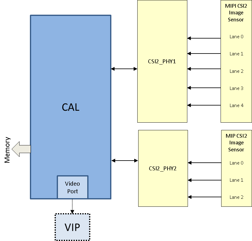
CAL provides up to two MIPI CSI-2 interfaces:
Module throughput up to 304 MPix/s
Transfer of pixels and data received by up to two D-PHY receivers (CSI2 PHY1 and CSI2 PHY2) to:
System memory, through 128-bit master interface on L3_MAIN interconnect
VIP module, through a video port
Shared FIFO with 8 KiB size
Maximum data rate of 1.2 Gbps per D-PHY i.e. Byte clock up to 150 Mhz (per errata i904)
Data merger for 2-, 3-, or 4-data lane configuration
Maximum frame size 65535 bytes x 16383 lines
Error detection and correction
Eight contexts to support eight dedicated configurations of virtual channel ID and data types
On-the-fly differential pulse code modulation (DPCM) decompression
3.3.4.3.2.1. SoC Hardware Feature
AM571x/DRA72x/DRA76x
CAL provides two MIPI CSI-2 interfaces
CSI2_PHY1 with 4 data lanes / 1 clock lane
CSI2_PHY2 with 2 data lanes / 1 clock lane
DRA71x
CAL provides one MIPI CSI-2 interface
CSI2_PHY1 with 2 data lanes / 1 clock lane
AM654x
CAL provides one MIPI CSI-2 interface
CSI2_PHY1 with 4 data lanes / 1 clock lane
3.3.4.3.3. Driver Architecture
The CAL driver is a video capture driver built around the V4L2 framework and is located in the directory drivers/media/platform/ti-vpe/ in the kernel tree.
Linux kernel driver for the CAL is implemented as per the V4L2 standard for capture devices. CAL driver is responsible only for the programming of the CAL device and built-ins D-PHY. For programming external video devices, we need a V4L2 subdevice driver which is used in conjunction with the V4L2 driver. It also uses some of the helper kernel libraries videobuf2 (VB2) for common buffer operations, queue management and memory management.
3.3.4.3.3.1. V4L2 endpoint device tree bindings
Different camera / video sources have different configuration parameters when interfacing with the CAL video ports. Common interfacing properties like data-lanes and clock-lanes can be different across different devices. V4L2 endpoint allows to describe these as part of device tree definition. This makes the CAL driver generic enough to have no dependency on the camera device. It also provides the flexibility to work with new cameras by doing simple device tree modifications.
Following is an example showcasing the DT entries of CAL device node and its usage when interfacing with a video source.
CAL device definition |
Camera device definition |
|---|---|
cal {
    #address-cells = <1>;
    #size-cells = <0>;
    status = "okay";
    ports {
        #address-cells = <1>;
        #size-cells = <0>;

        csi2_0: port@0 {
             reg = <0>;
             status = "okay";
             csi2_phy0: endpoint {
                 clock-lanes = <0>;
                 data-lanes = <1 2>;
                 remote-endpoint = <&csi2_cam0>;
             };
        };
        ...
        csi2_1: port@1 {
             reg = <1>;
             ...
        };
    };
};
|
camera-sensor@3c {
    compatible = "ovti,ov5640";
    reg = <0x3c>
    ...
    port {
        csi2_cam0: endpoint {
            clock-lanes = <0>;
            data-lanes = <1 2>;
            remote-endpoint = <&csi2_phy0>;
        };
    };
 };
|
3.3.4.3.3.2. V4L2 asynchronous subdevice registration
Each camera device that CAL driver communicates to is modelled as a V4L2 subdevice. In the probe sequence, CAL and camera drivers are probed at different time. V4L2 async subdevice binding helps to bind the CAL device and the camera device together. CAL driver looks for the camera entries in the endpoints and registers (v4l2_async_notifier_register) a callback if any of the requested devices become available. cal_async_bound implements the priority based binding which allows to have multiple cameras muxed against same video port. The device tree order determines which of these gets picked up by the driver. Note that the V4L2 g/s_input ioctls are not supported, userspace won’t be able to select specific camera with these ioctls.
Of course the target subdevice driver also needs to support the asynchronous registration framework. On top of this the subdevice driver must implements the following ioctls for the handshake with the CAL driver to work properly:
get_fmt()
set_fmt()
enum_mbus_code()
enum_frame_sizes()
s_stream()
In addition the subdevice driver must also calculate and make the current pixel rate (based on clocks, lanes and bits per pixels) available through the V4L2_CID_PIXEL_RATE control. This value is required by the CAL driver to properly configure the DPHY.
How to calculate the pixel rate?
See also
As you can see in the above link, typically the pixel rate is calculated as follows:
pixel_rate = link_freq * 2 * nr_of_lanes / bits_per_sample
The link frequency is usually computed from the sensor own PLL scheme/registers and is therefore sensor dependent. This is also the most accurate method.
Alternatively, if you trust that your sensor is configured correctly for a specific resolution/pixel format and frame interval then the pixel rate can be calculated using this simplified formula:
pixel_rate = total horizontal width * total vertical lines * frame per second
Here total horizontal width and total vertical lines includes blanking. This information is also sensor dependent or at least configuration dependent.
For example if we take a look at the ov5640 configuration for 1920x1080@30 fps:
total horizontal width = 2500
total vertical lines = 1120

pixel_rate = 2500 x 1120 x 30 = 84,000,000 pixels per second.
Now sometime even though a “sensor config mode” is labelled as 1920x1080@30 there may be variation in the actual register configuration which would yield a slightly slower or faster frame rate. This might be enough to make the DPHY handshake unsuccessful. Keep that in mind.
3.3.4.3.4. Driver Features
Note: this is not a comprehensive list of features supported/not supported.
3.3.4.3.4.1. Supported Features
Maximum frame size
Kernel v4.19 and prior: Limited by software to 1920x1200 pixels
Kernel v5.4 and above: Maximum frame size 65535 bytes x 16383 lines
Pixel formats (output)
Runtime pixel format availability is based on the sub-device capability
Use “yavta –enum-formats /dev/video1” to get an accurate list
Since CAL does not perform any format conversion the supported format are limited to native pixel format supported by the sub-device driver
YUV422 (YUYV,UYVY,VYUY,YVYU)
RGB (15, 16, 24, 32 bits)
Raw Bayer (8, 10, 12 bits)
V4L2 single-planar buffers and interface
Supports MMAP buffers (allocated by kernel from global CMA pool) and also allows to export them as DMABUF
Supports DMABUF import (Reusing buffers from other drivers)
3.3.4.3.4.2. Unsupported Features/Limitations
Media Controller Framework
Cropping/Selection ioctls
Capture forwarding through VIP port
Multi-stream interleaving/multiplex per port (i.e multiple VCs per port)
3.3.4.3.5. Driver Configuration
3.3.4.3.5.1. Kernel Configuration Options
ti-cal supports building both as built-in or as a module.
ti-cal can be found under “Device Drivers/Multimedia support/V4L platform devices” in the kernel menuconfig. You need to enable V4L2 (CONFIG_MEDIA_SUPPORT, CONFIG_MEDIA_CAMERA_SUPPORT) and then enable V4L platform driver (CONFIG_V4L_PLATFORM_DRIVERS) before you can enable ti-cal (CONFIG_VIDEO_TI_CAL).
3.3.4.3.6. Driver Usage
3.3.4.3.6.1. Loading ti-cal
If built as a module, you need to load all the v4l2-common, videobuf2-core and videobuf2-dma-contig modules before ti-cal will start.
3.3.4.3.6.2. Using ti-cal
When ti-cal is enabled, the capture device will appear as /dev/videoX. Standard V4L2 user space applications can be used as long as the capability of the application matches.
dmabuftest example
Use CAL to capture a 1280x800 YUYV video stream and display it on an HDMI display using DMABUF buffers.
dmabuftest -s 36:1920x1080 -c 1280x800@YUYV -d /dev/video1
yavta example
Capture 1280x800 YUYV video stream to file.
yavta -c60 -fYUYV -Fvout_1280x800_yuyv.yuv -s1280x800 /dev/video1
dmabuftest can be found from:
https://git.ti.com/glsdk/omapdrmtest
yavta can be found from:
http://git.ideasonboard.org/yavta.git
v4l2-ctl can be found from:
https://git.linuxtv.org/v4l-utils.git
3.3.4.3.6.3. Debugging
As ti-cal driver is based on the V4L2 framework, framework level tracing can be enable as follows:
echo 3 >/sys/class/video4linux/video1/dev_debug
This allows V4L2 ioctl calls to be logged.
echo 3 > /sys/module/videobuf2_core/parameters/debug
This allows VB2 buffers operation to be logged.
In addition ti-cal also has specific debug log which can be enabled as follows:
echo 3 > /sys/module/ti_cal/parameters/debug
3.3.4.3.6.4. Troubleshooting common capture problem
Bootup/Probe checks
First thing to look for is if the video devices are created or not; Check the bootlog for prints in the kernel bootlog.
Check device probe status
dmesg | grep ov5640
dmesg | grep video
Depending on the camera connected, the following prints can confirm the probe being successful.
Bootlog print |
Result |
|---|---|
cal-000: V4L2 device registered as video0 |
Camera probe success |
ov5640 4-003c: ov5640_read_reg: error: reg=30 ov5640 4-003c: ov5640_check_chip_id: failed to read chip identifier |
Camera not connected |
Alternatively you could also try to list all video devices:
v4l2-ctl --list-devices
This would shows all video device and which driver they belong to.
No video captured
When the capture application is launched, it is expected to start video capture and display frames on to display. Sometimes, no video is displayed on the screen. To identify this being an issue with capture, simple test can be done. Each CAL module has a dedicated interrupt line. If the capture is successful, the interrupt count should increase periodically.
Check interrupts to confirm capture failure
cat /proc/interrupts | grep cal
360:        120          CBAR 119 Level   cal
In the above example, one can conclude that
Capture from one or more CAL ports is working fine.
Note that the IRQs are shared for different ports of the same instance. This means, cal line will carry interrupts from both csi2_0 and csi2_1 ports.
If the number of interrupt stays at zero or no longer changes this usually means that the CAL engine does not detect video data. This might be cause by a handshake failure between the CSI2 D-PHY and the actual sensor or the sensor is not generating any data at all. Verifying that the clock pins or data pins are properly toggling might be necessary.
An other cause maybe that the currently provided V4L2_CID_PIXEL_RATE is not accurate and therefore the DPHY handshake with the sensor failed. In this case it is worth checking the calculated pixel rate.
Camera isn’t started, clock, data lanes are dead
This is a root cause where the camera board is not generating video signals in the desired format. Subdevice s_stream op is supposed to perform all the I2C transactions to indicate sensor to start streaming. Failing to get the proper clock at this time indicates some issue in the camera configuration. Most cameras have a power pin driver by one of the GPIO, make sure that the subdev driver requests for this GPIO.
One other cause maybe due to incorrect board mux or pinmux configuration. It does not hurt to double check these.
Video is being captured but image is distorted
If the image is distorted, you should double check that the sensor is generating the expected pixel clock. Also when trying to view the captured video, make sure you use the same frame size as used to capture it.
3.3.4.3.7. TI Board Specific Information
None at this time.