3.3.4.6. DSS (DSS6 & DSS7)
3.3.4.6.1. Introduction
This page gives a basic description of DSS (Display SubSystem) hardware, the Linux kernel drivers (tidss) and various TI boards that use DSS. The technical reference manual (TRM) for the SoC in question, and the board documentation give more detailed descriptions.
This page applies to TI’s v4.19 kernel.
3.3.4.6.2. Supported Devices
There are many DSS IP versions, all of which support slightly different set of features. DSS versions up to 5 are supported by the omapdrm driver, and DSS versions 6 and up are supported by the tidss driver. This document covers DSS6 and DSS7, which are used on the following TI SoCs or SoC families: K2G, AM65x, J721E.
3.3.4.6.3. Hardware Architecture
The Display Subsystem (DSS) is a hardware block responsible for fetching pixel data from memory and sending it to a display peripheral like an LCD panel or an DisplayPort monitor. DSS hardware can be divided into two major parts:
Display Controller (DISPC), which handles fetching the pixel data, doing color conversions, composition, and other pixel manipulation
Peripherals, which encode the raw pixel data to standard display signals, like MIPI DPI or DP.
In addition to the SoC’s DSS, boards often contain external display bridges (for example, DPI-to-HDMI bridge) and display panels.
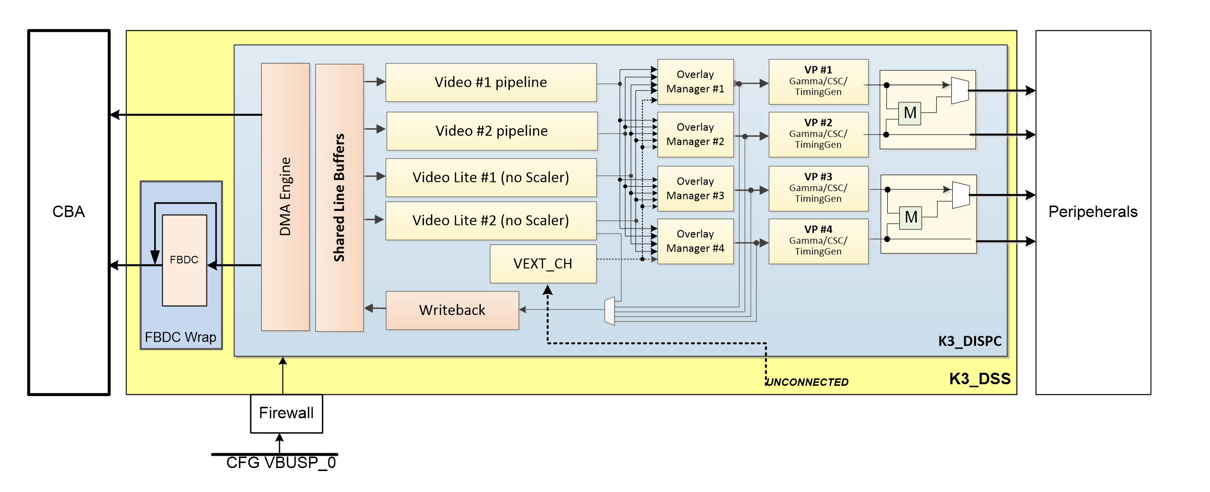
The above image gives an overview of the DSS (on J721E) hardware. The arrows show how pipelines are connected to overlay managers, which are further connected to video-ports, which finally create an encoded pixel stream for display on the LCD or monitor.
3.3.4.6.3.1. Display Controller (DISPC)
DISPC is the block which is responsible for fetching pixel data from the memory through DMA pipelines, and then create a pixel stream for the peripheral. The pixel stream comprises of a composition of one or more image layers which we finally want to present on the display. DISPC can be split into 3 major sub-blocks:
Pipelines
Overlay Managers (Compositors)
Video Ports (Timing generators)
The next three sub-sections provide details on these sub-blocks.
3.3.4.6.3.1.1. Pipelines
Pipelines (or DMA channels) consist of the HW block which performs DMA to fetch image pixels (of different color formats) from RAM. Besides performing DMA, pipelines perform other functions like replication, ARGB expansion, scaling, color conversion, VC1 range mapping on the input pixels before it’s passed on to the overlay manager. An overlay manager receives pixel data from one or more such pipelines, and performs the task of composing them and passing it on to the video-port.
There are two types of pipelines: VIDL and VID. The difference between the two is that VID pipelines support scaling, and VIDL does not. The number of pipelines within DSS varies with the DSS IP version used in the SoC.
3.3.4.6.3.1.2. Overlay Managers (Compositors)
Overlay managers are the blocks which take pixel data from one or more pipelines, layer them to form a composition, and create a pixel stream for the video-ports to consume.
The compositor part takes pixel data from multiple pipelines, composing them on the basis of their position with respect to the complete overlay manager size. Tasks like alpha blending, color-keying and z-order are also performed by the compositor in the overlay manager.
3.3.4.6.3.1.3. Video Ports (Timing generators)
Video ports take a pixel stream from an overlay manager, and encode it into a standard video signal which is understood by the LCD panel/monitor or an internal peripheral (like eDP). These video standards are specified by MIPI or general video/display bodies.
The timing generator part of the video port is responsible for providing the pixel stream generated by the compositor above according to the timings desired by the peripheral. The timing generator is a state machine which provides RGB data along with control signals like pixel clock, hsync, vsync and data enable. This timing info is used by the panel / peripheral to display the composited frame on the screen.
3.3.4.6.3.2. SoC Hardware Features
SoC |
DSS version |
Outputs |
Pipes |
Video ports |
|---|---|---|---|---|
K2G |
DSS6-UL |
DPI, DBI |
VID |
1 |
AM65x |
DSS7-L |
DPI, OLDI |
VID, VIDL |
2 |
J721E |
DSS7 |
DPI, DP, DSI |
2 x VIDL, 2 x VID |
4 |
3.3.4.6.4. Driver Architecture
The driver for DSS IP is tidss. tidss is a Direct Rendering Manager (DRM) driver, located in the directory drivers/gpu/drm/tidss/ in the kernel tree. tidss does not implement any 3D GPU features, only the Kernel Mode Setting (KMS) features, used to display pixel data on a display.
In addition to tidss, there are a number of bridge and panel drivers located in drivers/gpu/drm/bridge/ and drivers/gpu/drm/panel/ which provide support for various panels and bridges (both external and internal to SoC).
The mapping of DRM entities to DSS hardware is roughly as follows:
DRM term |
HW term |
|---|---|
plane |
DSS pipeline |
crtc |
DSS videoport |
encoder |
Internal and external bridges |
connector |
Connector or a panel |
3.3.4.6.4.1. Driver Features
Note: this is not a comprehensive list of features supported/not supported, and new features may be added in every release.
3.3.4.6.4.1.1. Supported Features
Outputs
MIPI DPI
DP
MIPI DPI
Active matrix
RGB
DisplayPort
SST
DRM Plane Features
CSC
Scaler
Z-order
Global alpha blending
Alpha blending (pre-multipled & non-pre-multiplied)
DRM CRTC Features
Gamma table
3.3.4.6.4.1.2. Unsupported Features/Limitations
LCD output
TDM
BT-656/1120
MIPI DBI/RFBI
Interlace
DisplayPort
MST
DSI
Not supported
3.3.4.6.5. Driver Configuration
3.3.4.6.5.1. Kernel Configuration Options
tidss supports building both as built-in or as a module.
tidss can be found under “Device Drivers/Graphics support” in the kernel menuconfig. You need to enable DRM (CONFIG_DRM) before you can enable tidss (CONFIG_DRM_TIDSS).
Enable DSS Display Subsystem support (CONFIG_DRM_TIDSS)
Enable TI DSS6 support (CONFIG_DRM_TIDSS_DSS6) for K2G SoC
Enable TI DSS7 support (CONFIG_DRM_TIDSS_DSS7) for K3 SoCs
Additional kernel config options may be needed, depending on the SoC and board.
Panels under “Device Drivers/Graphics support/Display Panels”
Bridges under “Device Drivers/Graphics support/Display Interface Bridges”
PHYs under “Device Drivers/PHY Subsystem”
3.3.4.6.5.2. Display Sharing Configuration Options
tidss supports sharing the display components with other drivers running on different cores.
tidss can be initialised with sharing information by adding the appropriate resource partitioning information in the device-tree files:
dss_planes: dss-planes {
        #address-cells = <1>;
        #size-cells = <0>;

        /* vid1, Owned by us */
        plane@0 {
                reg = <0>;
                managed = <1>;
        };

        /* vidl1, Reserved for jailhouse inmate */
        plane@1 {
                reg = <1>;
                managed = <0>;
        };

        /* vid2, owned by RTOS */
        plane@2 {
                reg = <2>;
                managed = <0>;
        };

        /* vidl2, marshalled to us by RTOS */
        plane@3 {
                reg = <3>;
                managed = <0>;
        };
};

dss_vps: dss-vps {
        #address-cells = <1>;
        #size-cells = <0>;

        /* Owned by jailhouse inmate */
        vp@0 {
                reg = <0>;
                managed = <0>;
        };

        /* Owned by RTOS */
        vp@1 {
                reg = <1>;
                managed = <0>;
        };

        /* Not owned by anyone
         * so keeping here
         */
        vp@2 {
                reg = <2>;
                managed = <1>;
        };

        /* Owned by us */
        vp@3 {
                reg = <3>;
                managed = <1>;
        };
};
In the above example, one plane vid1 and one video port vp4 is owned by us to drive a MIPI DPI output. Two planes, vid2 and vidl2, are owned by TI_RTOS for driving vp2, and therefore are marked as managed = <0>. Please note that vidl2 can be used by tidss using remote-device framework, but is actually owned by TI-RTOS. One plane vidl1 and one video port vp1 is used by a Linux virtual-machine, and therefore these are also marked as managed = <0>.
tidss also supports using one of the four interrupts, and this can be partitioned as:
dss_commons: dss-commons {
        #address-cells = <1>;
        #size-cells = <0>;

        interrupt-common {
                reg = <1>;
        };

        config-common {
                status = "disabled";
                reg = <0>;
        };
};
In the above configuration, tidss is configured to use common_s1 region for interrupt handling and the common_m region is marked as “disabled”, therefore making tidss dependant on another driver for initial configuration.
In the situation described above, tidss is required to depend on an external driver for configuration and sending frames / receiving events. tidss can perform these operations by utilising remote-device framework if the following information is provided:
dss_remote: dss-remote {
        #address-cells = <0>;
        #size-cells = <0>;

        remote-name = "r5f-tidss";
};
3.3.4.6.6. Driver Usage
3.3.4.6.6.1. Loading tidss
If built as a module, you need to load all the drm, tidss, bridge and panel modules before tidss will start. When tidss starts, it will prints something along these lines:
[    9.165740] [drm] Supports vblank timestamp caching Rev 2 (21.10.2013).
[    9.182786] [drm] No driver support for vblank timestamp query.
[    9.207746] [drm] Initialized tidss 1.0.0 20180215 for 4a00000.dss on minor 0
3.3.4.6.6.2. Using tidss
tidss is usually used by the windowing system like X server or Weston, so normally users don’t need to use tidss directly.
tidss device appears under /dev/dri/ directory, normally card0.
There is also so called DRM render device node, renderD128, which point to the same tidss device. Only buffer allocations can be done via the render node. The render node can be given more relaxed access restrictions, as the applications can only do buffer allocations from there, and cannot affect the system (except by allocating all the memory).
Low level userspace applications can use tidss via DRM ioctls. This is made a bit easier with libdrm, which is a wrapper library around DRM ioctls, or kms++ which is a C++11 library, or by Python bindings provided by kms++.
libdrm is included in TI releases and its sources can be found from:
https://gitlab.freedesktop.org/mesa/drm
libdrm also contains ‘modetest’ tool, which can be used to get basic information about DRM state, and to show a test pattern on a display.
Another option is kms++, a C++11 library for kernel mode setting which includes a bunch of test utilities and also V4L2 classes and Python bindings for DRM and V4L2. Some kms++ tools are included in TI releases. kms++ can be found from:
https://github.com/tomba/kmsxx
3.3.4.6.6.3. Testing tidss
kmstest from kms++ is a good tool for testing tidss features. Note that any other applications using DRM (Weston, X) must be killed first. Another tool from kms++ is kmsprint, which can be used to print various bits of information about tidss.
# kmsprint
Connector 0 (35) DP-1 (disconnected)
  Encoder 0 (34) NONE
Connector 1 (43) HDMI-A-1 (connected)
  Encoder 1 (42) NONE
    Crtc 1 (41) 1920x1200 154.000 1920/48/32/80 1200/3/6/26 60 (59.95)
        Plane 1 (36) fb-id: 57 (crtcs: 0 1) 0,0 1920x1200 -> 0,0 1920x1200 (AR12 AB12 RA12 RG16 BG16 AR15 AB15 AR24 AB24 RA24 BA24 RG24 BG24 AR30 AB30 XR12 XB12 RX12 A
R15 AB15 XR24 XB24 RX24 BX24 XR30 XB30 YUYV UYVY NV12)
        FB 57 1920x1200
# kmstest -c hdmi -r 640x480
Connector 1/@43: HDMI-A-1
  Crtc 1/@41: 640x480 31.500 640/16/64/120/- 480/1/3/16/- 75 (75.00) 0xa 0x40
  Plane 0/@28: 0,0-640x480
    Fb 77 640x480-XR24
press enter to exit
3.3.4.6.6.4. tidss properties
tidss supports configuration via DRM properties. These are standard DRM properties, and DRM documentation describes them. Also, kmsprint can be used to show the supported properties.
Property |
Object |
Description |
|---|---|---|
zpos |
plane |
Z position of a plane |
COLOR_ENCODING |
plane |
Selects between BT.601 and BT.709 YCbCr color encoding |
COLOR_RANGE |
plane |
Selects between full range and limited range YCbCr encoding |
alpha |
plane |
Full plane alpha-blending |
CTM |
crtc |
Color Transformation Matrix blob property. Implemented trough Color phase rotation matrix in DSS IP. |
GAMMA_LUT |
crtc |
Blob property to set the gamma lookup table (LUT) mapping pixel data sent to the connector. |
GAMMA_LUT_SIZE |
crtc |
Number of elements in gammma lookup table. |
3.3.4.6.6.5. Buffers
The buffers used for tidss can be either allocated from tidss or imported from some other driver (dmabuf import). All buffers must be contiguous.
tidss supports generic DRM dumb buffers. Dumb buffers are allocated using the generic DRM_IOCTL_MODE_CREATE_DUMB ioctl.
3.3.4.6.6.6. fbdev emulation (/dev/fb0)
DRM framework supports “emulating” the legacy fbdev API. This feature can be enabled or disabled in the kernel config (CONFIG_DRM_FBDEV_EMULATION). The fbdev emulation offers only basic feature set and the fb is shown on the first display. Fbdev emulation is mainly intended for kernel console or boot splash screens.