2.1. PRU ICSS EtherCAT Slave User Guide
2.1.1. Introduction
PRU-ICSS EtherCAT package is designed for the Sitara processor family (with PRU-ICSS IP) to enable customers add EtherCAT Slave protocol support to their system.
2.1.2. System Requirements
2.1.2.1. Supported Devices
- AM572x IDK 1.3A/B
- PRU-ICSS2 is used for validation [AM57x has 2 PRU-ICSS instances]
- AM571x IDK 1.3A
- AM437x IDK
- AM335x ICEV2
- AMIC11x ICE
- AMIC12x ICE
- AM654x IDK
Note
On AM654x IDK, the default strap setting of Ethernet PHYs is for RGMII mode. PRU-ICSS EtherCAT package supports only MII mode on AM654x. The IDK can be configured to support the use of the MII interface between the AM654x and the Ethernet PHYs. Please refer to Configuring the PRG0 and PRG1 Ethernet Interface to MII section in AM65x IDK EVM User’s Guide for more details.
2.1.2.2. Component Version
This release requires Processor SDK RTOS, see Processor SDK Getting Started Guide
| Component | Version |
|---|---|
| Processor SDK RTOS for AM57xx | 6.3.2 |
| Processor SDK RTOS for AM437x | 6.3.0 |
| Processor SDK RTOS for AM335x | 6.3.0 |
| Processor SDK RTOS for AM65X | 8.0.0 |
2.1.3. Reference Documents
2.1.4. Directory Structure
|   |--- docs

|       |---Industrial_Protocol_Package_Getting_Started_Guide.pdf

|       |---Industrial_Protocol_Package_Software_Developer_Guide.pdf

|       |---PRU_ICSS_EtherCAT.pdf

|       |---PRU_ICSS_EtherCAT_Release_Notes.pdf

|   |--- examples

|       |--- board

|           | --- common

|           | --- iceAM335x

|           | --- idkAM437x

|           | --- idkAM571x

|           | --- idkAM572x

|           | --- idkAM65xx

|           | --- include

|           | --- osal

|       |--- ethercat_slave

|           | --- esi

|       |--- tools

|           | --- bin2header

|   |--- protocols

|       |--- ethercat_slave

|               |--- docs

|                       |--- doxygen

|               |--- ecat_appl

|                       |--- EcatStack

|                       |--- esi

|                       |--- iceAM335x

|                       |--- idkAM57x

|                       |--- idkAM437x

|                       |--- idkAM65xx

|               |--- firmware

|                       |--- v1.0

|                       |--- v2.0

|                       |--- v2.1

|                       |--- g_v1.0

|               |--- include

|               |--- projects

|       |--- pdk_patches

|   |--- third_party

|       |--- protocols

|               |--- ethercat_slave

|                           |--- include

|                           |--- patch

|                           |--- stack_lib
Note
Refer to install path to get updated view of the changes in directory structure
2.1.5. Example Project Overview
TI has created two how-to videos that cover the information in this user guide. These videos break down all of the necessary steps to get your application up and running. Watching the videos while following along with the user guide is the easiest way to get started.
- Demonstrating DDR-less EtherCAT Slave on AMIC110
- Demonstrating TI ESC SPI Mode DDR-less AMIC110 with C2000 EtherCAT Slave
Note
Because there are many steps involved, you are encouraged to read through each of these sections to get the full picture before trying to create and run the example applications.
Building and running the EtherCAT slave example applications is broken down in to the following sections in the user guide:
- Generating Project files
- This section covers how to use the projectCreate.bat/.sh scripts to generate the CCS example projects after you have downloaded and installed PRU-ICSS-ETHERCAT-SLAVE and Processor SDK RTOS for your platform (see Component Version).
- Running EtherCAT Slave Application
- This section covers the differences between the Simple Demo Application and the Full Feature Demo Application and loading the application via SD card, QSPI, or CCS.
- On-chip Memory (DDRless) Execution of EtherCAT Slave Application
- This section covers the steps needed to run the EtherCAT slave application entirely from on-chip memory on the AMIC11x ICE or AMIC12x ICE boards. It contains important instructions for patching the Processor SDK to build thumb mode binaries, flash partitioning, and configuring the location of binaries in device memory.
- Building full feature EtherCAT Slave Application
- This section covers the additional steps needed to build the Full Feature EtherCAT Slave Application. Specifically, this section covers downloading the EtherCAT stack source code and patching it for the example application.
At a high level, you will be completing the following steps as you make your way through the guide or our how-to videos:
- Setting up your hardware
- Installing necessary software
- CCS
- Processor SDK RTOS
- PRU-ICSS-ETHERCAT-SLAVE
- EtherCAT slave stack code (necessary for Full Feature Application)
- TwinCAT EtherCAT master
- Generating and building the example application
- Loading and running the application
- Validating application results using TwinCAT
2.1.6. Generating Project files
2.1.6.1. Steps to generate Project files
Setup the environment variables
Edit the file
[INSTALL-DIR]/protocols/<protocol name>/projects/projectCreate.bat or .shto align to the environment in your machine. All these paths should be accurate and mandatory; otherwise it will cause errors.- CCS_INSTALL_DIR - Set the path where the recommended version of CCS is installed in user machine. For example, if CCSv10.4.0 is installed in default path, set it to “C:\ti\ccs1040\ccs”.
Note
Use the path up to where the folder ‘eclipse’ is located.
- CCS_WORKSPACE_LOC - Set the CCS workspace location. This folder will be created if it doesn’t exist already.
Note
Use the default path provided for CCS_WORKSPACE_LOC as a reference.
- IA_SDK_HOME - Specify the IA_SDK_HOME based on the the directory where the industrial package is installed. If the package is installed in a custom directory, make sure this path is modified properly.
- PDK_INSTALL_PATH - Set the path where PDK RTOS package is installed (Refer to default path in projectCreate.bat)
Note
Use the path up to where the folder ‘ti’ is located.
- PROJECT_CREATE_DIR - Set the folder where the created project will be kept. User can import the projects from this directory to CCS
- PROJECT_CREATE_OPTIONS_FILE_DIR - Specify the directory where the project create options files are kept. This folder contains the *.txt files which specify the project settings (linked files, predefined symbols, compiler and linker options for a specific project)
Open Command/Shell Prompt and navigate to
[INSTALL-DIR]/protocols/<protocol name>/projectsRun projectCreate.bat or projectCreate.sh. The batch file takes three mandatory command line arguments (The mandatory arguments are case sensitive!)
Usage format: projectCreate.bat [SOC] [PROCESSOR] [PROJECT_NAME]
- [SOC]
- The valid values for first command line argument [SOC] are
- AM571x - To generate a project specific to AM571x
- AM572x - To generate a project specific to AM572x
- AM437x - To generate a project specific to AM437x
- AM335x - To generate a project specific to AM335x
- AMIC11x - To generate a project specific to AMIC11x
- AMIC12x - To generate a project specific to AMIC12x
- AM65xx - To generate a project specific to AM65xx
- The valid values for first command line argument [SOC] are
- [PROCESSOR]
- The valid values for second command line argument [PROCESSOR] are
- arm - To generate a project specific to ARM core
- r5f - To generate a project specific to R5F core (supported only for AM65xx)
- The valid values for second command line argument [PROCESSOR] are
- [PROJECT_NAME]
- The valid values for third command line argument [PROJECT_NAME]
to be used with EtherCAT slave installer package
- ethercat_slave_full - to generate EtherCAT slave full application project
- ethercat_slave_demo - to generate EtherCAT slave demo application project
- ecat_ti_esc_spi_master - to generate EtherCAT TI ESC SPI Mode Master application project (supported only for AM572x)
- ecat_ti_esc_spi_slave - to generate EtherCAT TI ESC SPI Mode Slave (ASIC Mode) application project (supported only for AMIC11x)
- ethercat_slave_cia402 - to generate Single-Chip Motor-Control application through Standard CiA402 Drive Profile over EtherCAT (supported only for AM437x)
- The valid values for third command line argument [PROJECT_NAME]
to be used with EtherCAT slave installer package
Note
Ensure that Code Composer Studio is not running when executing
projectCreate.bat or projectCreate.sh. If not, the eclipsec may
throw errors
- Usage example 1 : projectCreate.bat AM572x arm ethercat_slave_demo
- To generate the project files for EtherCAT slave demo application for AM572x ARM core by overwriting the project if it is already existing in PROJECT_CREATE_DIR\PROJECT_NAME_SOC_PROCESSOR
- Usage example 2 : projectCreate.bat AM65xx r5f ethercat_slave_full
- To generate the project files for EtherCAT slave full application for AM65xx R5F core by overwriting the project if it is already existing in PROJECT_CREATE_DIR\PROJECT_NAME_SOC_PROCESSOR
Note
If the project create is successful, the generated project files will
be found in [INSTALL-DIR]/protocols/<protocol name>/projects/PROJECT_NAME_SOC_PROCESSOR
2.1.6.2. More info
The projectCreate.bat or.sh utilizes the project arguments provided in
[INSTALL-DIR]/protocols/<protocol name>/projects/ccsproject_args to
generate the project file
2.1.7. Running EtherCAT Slave Application
Note
NOTE 1: Package supports two different versions of EtherCAT application.
- 1. Simple Demo Application - An EtherCAT sample application built
- using pre-built EtherCAT stack library. This allows limited development using SSC5.12 stack library via Sample Application Interface which provides controlling 32- bit input and 32-bit output. Object dictionary adaptation is not possible in this evaluation version. This will be the default configuration for EtherCAT. The project files for this application can be generated following Generating Project Files.. The example application will be delivered in source, but the EtherCAT stack will be delivered in object format only.
- 2. Full Feature Demo Application - This is a full-fledged
- application and provides full flexibility and configurability. However this application need access to complete stack source. As per the SLA terms, TI cannot distribute the stack (Beckhoff Slave Sample Code) in source format. Therefore, to build this application, user must get the SSC 5.12 source code from ETG website and apply the provided patch. The project files for this application can be generated following Generating Project Files. For more information, refer the section on “Building Full Feature EtherCAT Application” of this document.
NOTE 2: Both EtherCAT applications support non-volatile storage of ESI EEPROM. The application writes the data into non-volatile QSPI memory only in INIT and PREOP states. This can be disabled or enabled on full featured application by defining/undefining EEPROM_SPI macro in tiescbsp.h. This feature cannot be modified in limited demo
To test the TI EtherCAT Slave sample application, the user first needs to create the project files.
- For Simple Demo Application use ethercat_slave_demo as the command line argument
- For Full Feature Demo Application use ethercat_slave_full as the command line argument
The created project can be imported to the recommended version of CCS
and built. Upon successful build, ethercat_slave_demo_[SoC]_arm.out
or ethercat_slave_full_[SoC]_arm.out will be generated. The SD card
image named app will also be generated by the default post-build
scripts of the CCS project. This can be flashed to QSPI or copied to SD
card. Please see the Getting Started
Guide
for details on building an application. Alternatively,
ethercat_slave_demo_[SoC]_arm.out or
ethercat_slave_full_[SoC]_arm.out can be load/run from CCS to
Cortex-A CPU of Sitara processor. The application uses the LED light
controls to demonstrate the EtherCAT Slave interface.
To test TI EtherCAT slave sample app - one can use TwinCAT or any other compatible EtherCAT master. Below are the steps to use TI slave with TwinCAT.
Note
To use PRU-ICSS1 on the AM571x IDK, the
#define PRUICSS_INSTANCE need to set to PRUICSS_INSTANCE_ONE in
the [INSTALL-DIR]/protocols/ethercat_slave/include/tiesc_soc.h file
Note
Additional RTSC cfg files for the projects are included in the package
for each SoC with System Analyzer and other debug features enabled by
default. These files can be found at
[INSTALL-DIR]/protocols/ethercat_slave/ecat_appl/[soc]_app_debug.cfg.
Detailed tutorials on using System Analyzer with Code Composer Studio
can be found
here
2.1.7.1. TI_ESC slave setup with TwinCAT3
Install TwinCAT3. A 7 days free trial license (can be renewed indefinitely for evaluation purpose) is available for free download from the Beckoff website TwinCAT 3 Download. Select the eXtended Automation Engineering (XAE) mode of installation.
Copy the ESI file to <Drive>:\TwinCAT\3.1\Config\Io\EtherCAT folder
- ESI file for EtherCAT Slave demo application is
[INSTALL-DIR]/examples/ethercat_slave/esi/TiEtherCATLib.xml - ESI file for EtherCAT Slave full application is
[INSTALL-DIR]/protocols/ethercat_slave/ecat_appl/esi/TI_ESC.xml - ESI file for EtherCAT TI ESC SPI Mode (ASIC Mode) Slave
application is
TMDSECATCNCD379D EtherCAT slave (SPI).xmlavailable in ControlSUITE
- ESI file for EtherCAT Slave demo application is
Start the TwinCAT XAE Shell
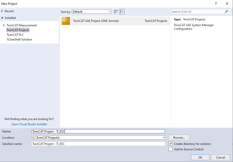
Create a new TwinCAT XAE Project (XML format): File > New > Project > TwinCAT Project
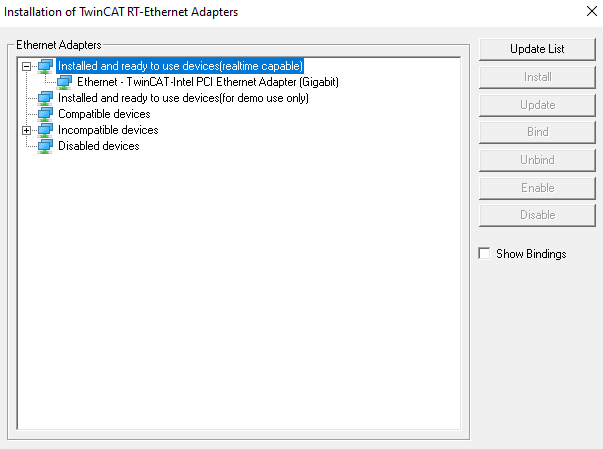
Go to TwinCAT > Show Realtime Ethernet Compatible Devices and Install TwinCAT RT Ethernet intermediate driver. For best performance, it is recommended to use a compatible NIC card listed Supported Network Controller by Beckhoff Ethernet Driver . For the first time only you need to set the PC’s Ethernet port, which is used as the EtherCAT port. Go to TwinCAT > Show Realtime Ethernet Compatible Devices and check if the ethernet adapter is listed below “Installed and ready to use devices” before attempting to scan the slave.

Note
If your computer go to sleep and after awake it TwinCAT lost connection with slave(s) and/or is not able to discover EtherCAT IO devices, you can fix this issue by going in TwinCAT to your Ethernet adapters, and Disabling / Enabling your NIC.
Connect Ethernet cable from TwinCAT PC to EtherCAT IN/Port0 of the default PRU-ICSS instance on IDK(See the table below to find the default instance). If you have multiple IDKs in chain, please connect from EtherCAT OUT/Port1 to IN/Port0 of next IDK. For the last IDK in chain, OUT/Port1 will be left open (if NOT using redundancy mode).
Below table gives details on the default PRU-ICSS instance on all the supported ICE and IDK Boards
SoC / Board PRU-ICSS Instance Available Default PRU-ICSS Instance AM335x / AM335x ICEv2 / AMIC11x / AMIC11x ICE PRU-ICSS1 PRU-ICSS1 AM437x / AM437x IDK / AMIC12x / AM437x IDK PRU-ICSS0, PRU-ICSS1 PRU-ICSS1 AM572x / AM572x IDK / AM571x / AM571x IDK PRU-ICSS1, PRU-ICSS2 PRU-ICSS2 AM65xx / AM65xx IDK PRU-ICSS0, PRU-ICSS1, PRU-ICSS2 PRU-ICSS0
Note
For changing the PRU-ICSS instance to be used by EtherCAT, the
#define PRUICSS_INSTANCEmacro needs to be set accordingly in the[INSTALL-DIR]/protocols/ethercat_slave/include/tiesc_soc.hfile.Power up the device.
2.1.7.2. Starting EtherCAT application
On powering up the device and loading the application, you should see digital output LED’s 2, 4, 6 and 7 on (except for AMIC11x ICE, where LEDs 2 and 5 should be on). This indicates that slave is up and in INIT state.
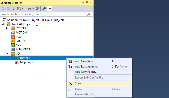
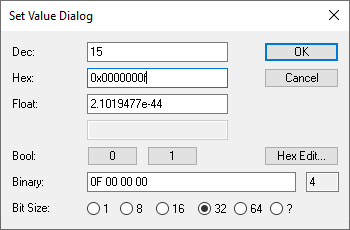
In Solution Explorer, go to TwinCAT project > I/O > Devices. Right click on Devices and select Scan. Press OK in the next dialog to start scanning for EtherCAT devices.
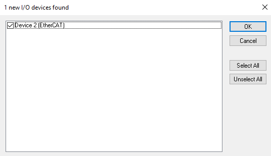
Once an EtherCAT compatible device has been detected on this Ethernet port, the following dialog shows up. Note that there is a tick mark next to the adapter to which the IDK is connected. Press OK and confirm to start “Scan for boxes”.
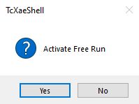
TI Box n(TIESC) will be detected automatically. The TI device will be listed “Box n (TIESC-*)”. Press Yes to activate Free Run. This will put TI ESC into OP mode. TIESC number is based on the platform and application. Please check the ESI file for more details.
Note
If running TwinCAT 2 on Windows XP, now select Device1 (EtherCAT) and goto Actions > Select Set/Reset TwinCAT to Config Mode or use shortcut SHIFT-F4. Alternatively, if running TwinCAT 3 on Windows 7, now select Device1 (EtherCAT) and goto TwinCAT and then Reload Devices.
The EtherCAT device state can be displayed by selecting a Device (Double click on Device) and then selecting the Online tab. The device should be in the OP state with no Lost Frames or Tx/Rx Errors.
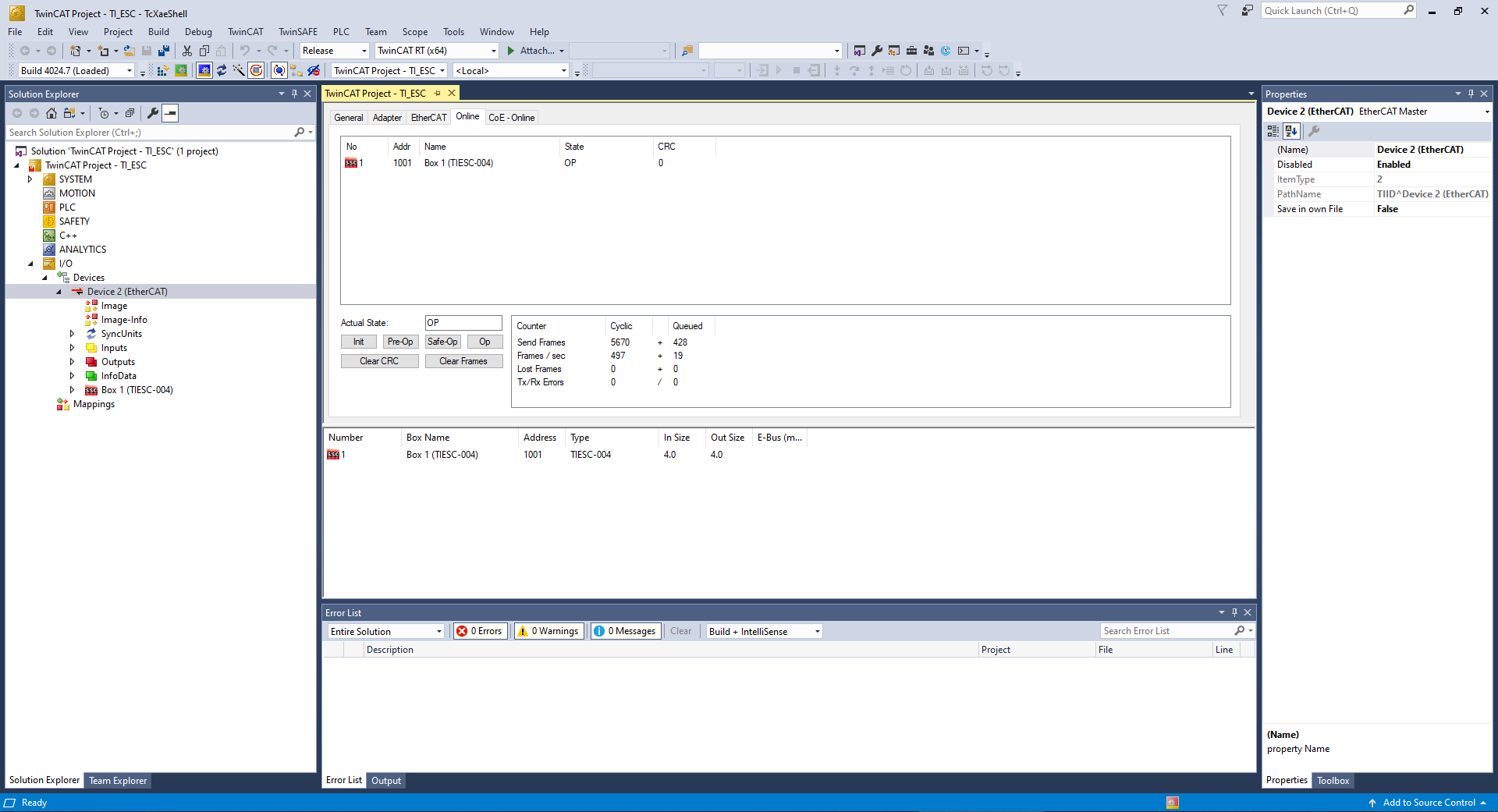
The user can control 8 digital out LEDs using TwinCAT. Expand the box to see Process Data Inputs(PDI) and Outputs(PDO).
Right-click on “Box n (TIESC-*)” > RxPDO > 32Bit Output. Select Online Write.
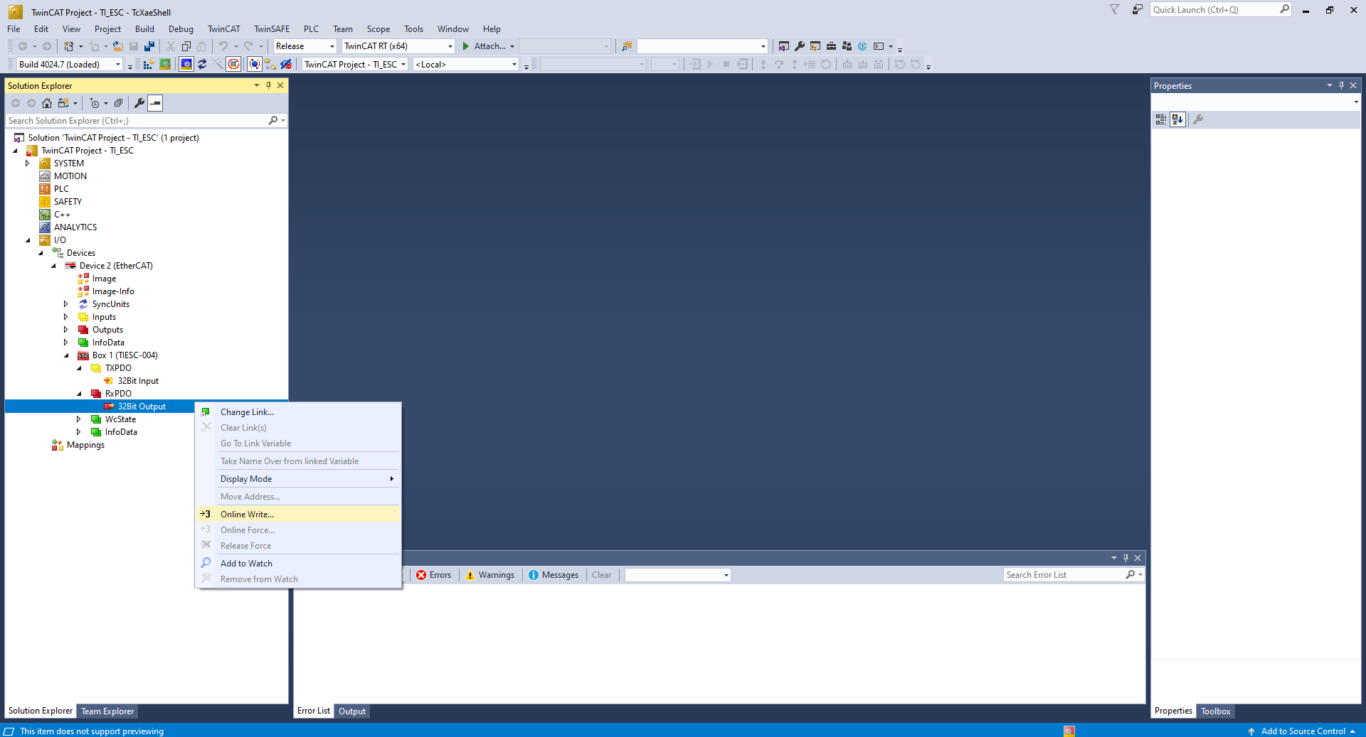
Enter the value in hexadecimal format, where each bit in the lowest 8 bits represents an output. Changing the output value will set/clear the appropriate LED(s).
Note
The images shown above are from EtherCAT Slave demo application. If you load EtherCAT Slave full application by following steps from Building full feature EtherCAT Slave Application, you will see LED1 to LED8 in “Box n (TIESC-*)” > DO Outputs > LED. Each LED can be turned on and off by selecting online write and setting the value to 1 and 0 respectively.
Note
For running EtherCAT slave in DC mode, please see Building full feature EtherCAT Slave Application section.
2.1.7.3. TI ESC SPI Interface to Support ASIC mode for EtherCAT
2.1.7.3.1. TI ESC SPI Slave (ASIC Mode) on AMIC11x with AM572x
The TI ESC SPI Interface applications (SPI Master and Slave mode) are added to provide EtherCAT support over SPI to non-EtherCAT devices.
These applications are a demonstration of running the existing Beckhoff SSC stack on a MCU/MPU that communicates over SPI with a Sitara/AMIC110 device running the EtherCAT firmware. This will help to extend EtherCAT functionality to non-EtherCAT devices without replacing the existing MCU/MPU.
The package contains TI ESC SPI Master mode application for AM572x and TI ESC SPI Slave mode application for AMIC11x.
- TI ESC SPI Slave Mode : This application runs the EtherCAT firmware and it responds to the ET1100 compatible SPI requests from the Master application running the Beckhoff SSC stack. As EtherCAT stack and firmware only communicate via memory access, the Master sends only memory read and write requests over SPI and the Slave executes and responds to the requests. PDI and SYNC signals from firmware are redirected over GPIO pins from the Slave to the Master. The SPI Slave application doesn’t contains the Beckhoff SSC stack.
- TI ESC SPI Master Mode : This application runs the Beckhoff SSC stack and doesn’t contains the EtherCAT firmware. The Master application communicates with the Slave application over SPI.
For the TI ESC SPI Mode projects, in the project build procedure the [PROJECT_NAME] need to be replaced in the final command with
- ecat_ti_esc_spi_master : For generating the TI ESC SPI Master Project
- ecat_ti_esc_spi_slave : For generating the TI ESC SPI Slave Project
Before uploading the applications, make the pin connections as shown in the image below
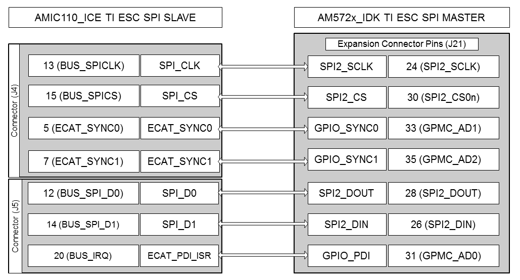
TI ESC SPI Mode Pin Map
To start the applications, first run the ‘ecat_ti_esc_spi_slave’ application and then run the ‘ecat_ti_esc_spi_master’ application
Constraints on the ET1100 SPI protocol supported by the TI ESC SPI Mode Slave Application on AMIC11x
- The Maximum SPI Baud rate currently supported is 6MHz
- Only the following ET1100 commands are supported
- ET1100_SPI_COMMAND_READ_WAIT -> 0x03
- ET1100_SPI_COMMAND_WRITE -> 0x04
- In case of Read command, 3 wait state bytes are required
- Delay required after every SPI transfer
- Read transfer -> 20us delay
- Write transfer -> 20us delay
2.1.7.4. Single-Chip Motor-Control application
The Single-Chip Motor-Control application uses EtherCAT as the industrial communication protocol, and demonstrates single-chip motor control using the standard CiA402 Drive profile over an EtherCAT network. The IEC standard of CiA 402 specifies a set of generic default PDOs available to all drives, as well as a set of specific default PDOs applicable only to a specific class of drives such as servo drives, frequency inverters, or stepper motors. IEC 61800-7-201 and IEC 61800-7-301 specify the CiA 402 drive profile, which is mapped to EtherCAT. The EtherCAT Slave Stack Code (SSC) provides a sample implementation of the CiA 402 drive profile. In this application, the default implementation from the SSC is used for motor control demonstration. More details on the CiA 402 Drive profile and the stack implementation can be found in EtherCAT Slave Stack Code Application Note ET9300 and ETG6010 CiA402 Implementation Directive.
The application demonstrates a sensored three-phase, sensored field oriented control (FOC) for a single PMSM using the on-chip AM437x ADCs. The EnDat 2.2 master interface provides position information with a EnDAT encoder attached to the motor. The motor-control application has been validated using a permanent-magnet motor (BLY171D-24V-4000, Anaheim Automation). The motor can be coupled to an EnDat 2.2 encoder (ROQ 437, Heidenhain) to provide position information to the FOC algorithm. The IDK uses the three terminals of J17 to provide the motor drive.
To build and run the single-chip motor drive application, install the following the SDKs:
- EtherCAT Slave Package (version 01.00.07 or later)
- Industrial Drives Package (version 01.00.02 or later)
For the single-chip drive application, the “DRIVES_SDK_INSTALL_PATH” variable must also be updated in the projectCreate.sh/.bat script of EtherCAT Slave package to point to the installation directory of Industrial Drives Package. Provide the “Project_Name” argument as “ethercat_slave_cia402” to the projectCreate script to generate the single-chip drive application files. The final command will look like:
projectCreate.sh/.bat AM437x arm ethercat_slave_cia402
Detailed description on the application and setup can be found in the Single Chip Drive for Industrial Communications and Motor Control TI Design (TIDEP0025)
A patch on top of PRU-ICSS-Industrial_Drives_01.00.02.03 is needed, if PRU-ICSS-EtherCAT_Slave_01.00.10.00 is being used.
It can be downloaded from here .
You can apply the patch using one of the following options:
git - Run following after going to
[INSTALL-DIR]directory for Industrial Drives Packagedos2unix Build-fixes-for-using-PRU-ICSS-Industrial_Drives_01.00.02.03-with-PRU-ICSS-EtherCAT_Slave_01.00.10.00.patch git apply Build-fixes-for-using-PRU-ICSS-Industrial_Drives_01.00.02.03-with-PRU-ICSS-EtherCAT_Slave_01.00.10.00.patch
patch tool
Download Windows Patch Utility from gnuwin32 sourceforge. ( Note that this is not a TI tool - See licensing information page for more details)
Download Dos2Unix/Unix2Dos-Text file format converters from gnuwin32 sourceforge. ( Note that this is not a TI tool. See licensing information page for more details)
Launch DOS Command prompt ( Start->Run->cmd).
Execute unix2dos.exe as given below (PATCH_FILE_FULL_PATH is the full path where PATCH file is kept in PC)
[Dos2Unix/Unix2Dos-DIR]/bin/unix2dos.exe [PATCH_FILE_FULL_PATH]/Build-fixes-for-using-PRU-ICSS-Industrial_Drives_01.00.02.03-with-PRU-ICSS-EtherCAT_Slave_01.00.10.00.patch
CD to patch file utility bin folder.
Execute patch.exe as given below (INSTALL-DIR is the Industrial Drives Package installation directory)
patch.exe -i [PATCH_FILE_FULL_PATH]/Build-fixes-for-using-PRU-ICSS-Industrial_Drives_01.00.02.03-with-PRU-ICSS-EtherCAT_Slave_01.00.10.00.patch -d INSTALL-DIR -p 1 --verbose
2.1.8. On-chip Memory (DDRless) Execution of EtherCAT Slave Application
EtherCAT Slave Package provides support for application execution using only on-chip memory i.e. DDRless on AMIC11x and AMIC12x SoCs. Both the full mode application and demo mode application support on-chip memory execution. Also the TI ESC SPI Slave mode (ASIC mode) on AMIC11x supports on-chip memory execution. To build any of the above application in on-chip memory execution mode follow the below process
- Generate the project files of the required application for AMIC11x or AMIC12x SoC using the Steps to generate Project files
- Import the generated project into CCS and select
AMIC12x_release or AMIC11x_releaseas the build configuration, by default release configuration is pre-configured to compile in on-chip memory execution mode
2.1.8.1. On-chip Memory (DDRless) Execution on AMIC12x ICE
On AMIC12x in On-chip Memory (DDRless) execution setup, the EtherCAT
Slave application loads and runs out of L2_cache in SRAM mode and OCMC
memory. To build any AMIC12x EtherCAT application in DDRless mode, the
AMIC12x_release configuration has to be used. The generated
application needs to be used along with a modified SBL or updated Gel
files. AMIC12x on-chip Memory execution supports using mmcsd, QSPI Flash
and JTAG to load the application.
2.1.8.1.1. Modifying SBL for AMIC12x on-chip Memory Execution
The AMIC12x on-chip memory application utilizes the L2_cache as SRAM.
By default, the SBL configures the L2_cache as a cache memory and not
SRAM. As we need the memory to be configured as SRAM before starting the
application, the SBL needs to be modified for the same. A patch
available in the EtherCAT Slave Package for modifying the SBL source at
this path
[INSTALL-DIR]/protocols/pdk_patches/04.03.00/AMIC12x_DDR-less_MLO.patch.
The SBL needs to be rebuilt after applying the patch. This patch will
modify both the mmcsd and QSPI bootloaders. Use the below command to
apply the patch
patch.exe -i [INSTALL-DIR]/protocols/pdk_patches/04.03.00/AMIC12x_DDR-less_MLO.patch -d [PDK_INSTALL_PATH]/pdk_am437x_1_0_10/packages -p0
Details on patching and rebuilding the Processor SDK can be found at
Processor SDK Patching and
Rebuilding.
SBL is built under the target starterware.
2.1.8.1.2. Modifying Gel files for AMIC12x on-chip Memory Execution
For the same reason mentioned above we also need to modify the Gel files
before upload the AMIC12x on-chip memory application via JTAG. Please
add the below lines to the function AM43xx_IDK_EVM_Initialization()
in the file
ccsv7/ccs_base/emulation/boards/idk_am437x/gel/AM437x_EVMs.gel.
GEL_TextOut("Enabling L2 as SRAM...  \n");
*((unsigned int*) 0x44E10654)      =  4;
*((unsigned int*) 0x44E101E0)      =  0x10000;
GEL_TextOut("Enabled L2 as SRAM...  \n");
Note
The modified SBL and Gel files will NOT work with DDR based cache enabled AMIC12x or AM437x applications. The above mentioned modifications need to be reverted back if DDR-less mode is not used
2.1.8.2. On-chip Memory (DDRless) Execution on AMIC11x ICE
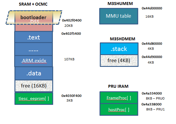
On AMIC11x in On-chip Memory (DDRless) execution setup, the EtherCAT
Slave application loads and runs out of OCMC memory and utilizes M3
internal and shared memory. To build any AMIC11x EtherCAT application in
DDRless mode, the AMIC11x_release configuration has to be used. The
generated application needs to be flashed on the SPI Flash memory of the
board, along with a special SBL file available from Processor SDK. This
implementation of the EtherCAT Slave application lays out the memory map
of the application and the bootloader as described in the figure below:
2.1.8.2.1. Patching Processor SDK for Thumb Mode binaries
For DDRless application to build, it is critical that Processor SDK is
build in Thumb Mode. A patch file has been included in the package for
the same. This file can be found at
[INSTALL-DIR]/protocols/pdk_patches/04.03.00/AM335x_PDK_thumb_mode.patch.
After applying this package the Processor SDK needs to be cleaned and
rebuilt.
2.1.8.2.2. Flash Partitioning
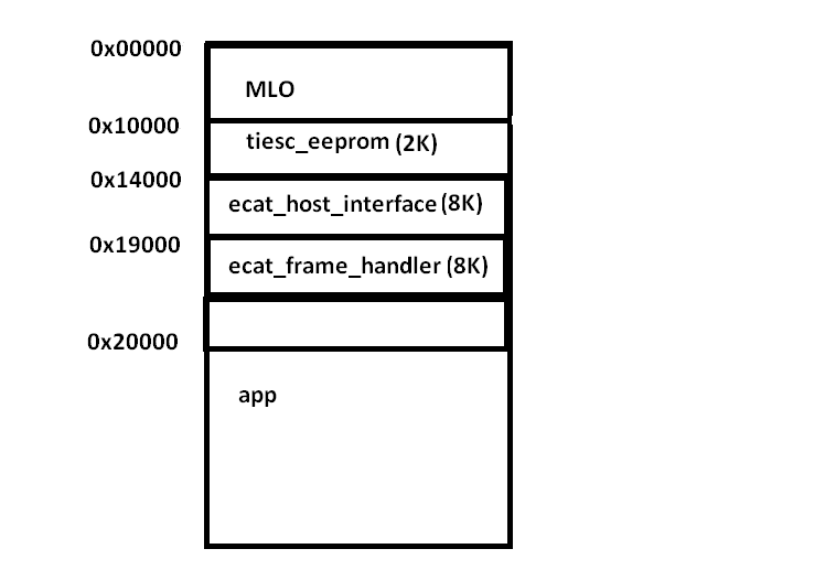
During normal operation, users are required to flash SBL in 0x000000 and App at 0x20000. In DDRless mode, the SBL has to load additional binaries to PRU0 IRAM and PRU1 IRAM and store TIESC EEEPROM, the following flash memory map was set to flash the application binaries.
2.1.8.2.3. Flashing application binaries
The SBL and Application can be flashed to the SPI flash as described Booting Via McSPI
2.1.8.2.4. Configuring location of binaries in device memory
The load location for binaries loaded by the bootloader are configured
by providing the location in the TI IMAGE header appended to these
binaries. The prebuilt ti image binaries for ecat_frame_handler and
ecat_host_interface can be found at
[INSTALL-DIR]/protocols/ethercat_slave/firmware/v1.0/. Pre-built
binary of tiesc_eeprom can be found at path
[INSTALL-DIR]/protocols/ethercat_slave/ecat_appl/iceAM335x/
The process of generating the binaries by providing the device memory location and appending the TI IMAGE header to the binary is described below:
Converting PRU firmware to TI image format:
Converting PRU0 firmware (ecat_frame_handler)
tiimage.exe 0x4a334000 NONE ecat_frame_handler.bin ecat_frame_handler_ti.bin
Converting PRU1 firmware (ecat_host_interface)
tiimage.exe 0x4a338000 NONE ecat_host_interface.bin ecat_host_interface_ti.bin
Converting TIESC EEPROM Data (tiesc_eeprom)
tiimage.exe 0x4030F400 NONE tiesc_eeprom.bin tiesc_eeprom_ti.bin
ecat_frame_handler.bin and ecat_host_interface.bin are available at [IA_SDK_HOME]\protocols\ethercat_slave\firmware\v1.0
Below is the detailed procedure:
- Open SSC Tools
- Go to Tools->EEPROM Programmer
- In EEPROM Programmer, go to File->Open. Here select the TI_ESC.xml ESI file from the path “[IA_SDK_HOME]\protocols\ethercat_slave\ecat_appl\esi”
- Now in the Device Description drop down select “TIESC-001”
- File->Save as. Select “Save as type” as “binary (*.bin)”. Provide the path and Save.
2.1.8.2.5. Configuring offset of binaries in SPI flash
After the TI image binaries are created, users are required to program the binaries to the SPI flash using the flash writer from <PDK_INSTALL_DIR\packages\ti\starterware\tools\flash_writer\spi_flash_writer_AM335X.out onto the EVM. For out of the box user experience the three additional binaries need to be flashed at the following offsets.
| Binary Name | Offset |
|---|---|
| ecat_frame_handler_ti.bin | 0x19000 |
| ecat_host_interface_ti.bin | 0x14000 |
| tiesc_eeprom_ti.bin | 0x10000 |
2.1.8.2.6. SBL for DDRless Execution
eeprom data along with the application. | More details on building the bootloader for DDR-less execution on AMIC11x can be found here.
2.1.8.2.7. TI ESC SPI Slave (ASIC mode) on AMIC11x with On-chip memory execution
The process mentioned in On-chip Memory (DDRless) Execution of EtherCAT Slave Application is also applicable for TI ESC SPI Slave (ASIC mode) on AMIC11x. The only difference is the eeprom binary to be flashed is different for ASIC mode. The ESI file “TMDSECATCNCD379D EtherCAT slave (SPI).xml” used to be generate the eeprom binary is available in the controlSUITE.
tiesc_eeprom.bin for ASIC mode can be generated from the ESI file using SSC Tool. Below is the detailed procedure:
- Open SSC Tools
- Go to Tools->EEPROM Programmer
- In EEPROM Programmer, go to File->Open. Here select the “TMDSECATCNCD379D EtherCAT slave (SPI).xml” ESI file from the controlSUITE
- Now in the Device Description drop down select “TMDSECATCNCD379D EtherCAT slave (SPI)”
- File->Save as. Select “Save as type” as “binary (*.bin)”. Provide the path and Save.
The load location needs to be configured in the generated eeprom binary. Please follow the steps mentioned in Configuring location of binaries in device memory for the same.
2.1.9. Building full feature EtherCAT Slave Application
[INSTALL-DIR]/examples/ethercat_slave folder is a limited
development application. To have a full development capability on Sitara
processor, it is necessary to get the EtherCAT Slave Stack Code (SSC)
from Beckhoff and build this for Sitara processors. Ethercat full mode
example application provides all board specific implementation sources
for EtherCAT and a patch file to modify Beckhoff source files for Sitara
processors. This application can be found in
[INSTALL-DIR]/protocols/ethercat_slave/ecat_appl. This folder also
includes the configuration xml file to be used for testing and it can be
found in[INSTALL-DIR]/protocols/ethercat_slave/ecat_appl/esi
folder.
The steps for building full feature EtherCAT application using Beckhoff stack source code are given below.
- Download EtherCAT stack version 5.12 from ETG website and extract it to a local folder.
- Generate the patched EtherCAT Slave stack code source files using any one of the below mentioned methods
- Copy the patched Beckhoff source files (.c and .h) to
[INSTALL-DIR]/protocols/ethercat_slave/ecat_appl/EcatStack - Generate CCS project following Steps to generate Project files
- Launch CCS and import ethercat_slave_full application project found
at the Project create directory (say,
[INSTALL-DIR]/protocols/ethercat_slave/projects) to CCS - Define macros in ecat_appl\EcatStack\ecat_def.h as required for
your application.
- Ensure that TIESC_HW is set to 1
- For running default application, set TIESC_APPLICATION to 1 and CiA402_DEVICE to 0
- For running CiA402 application, set TIESC_APPLICATION to 0
and CiA402_DEVICE to 1.
- Please note `Option #2 <PRU_ICSS_EtherCAT.html#generating-ethercat-sources-using-beckhoff-ssc-tool-option-2>`__ will NOT work for CiA402 application. Please use `Option #1 <PRU_ICSS_EtherCAT.html#generating-ethercat-sources-using-the-patch-file-option-1>`__ to generate the sources.
- Build the project. This will generate the application binary which can be used to run on Sitara processors.
2.1.9.1. Generating EtherCAT sources using the Patch file (Option #1)
- Download Windows Patch Utility from gnuwin32 sourceforge. ( Note that this is not a TI tool - See licensing information page for more details)
- Download Dos2Unix/Unix2Dos-Text file format converters from gnuwin32 sourceforge. ( Note that this is not a TI tool. See licensing information page for more details)
- Extract the zip files to the Windows PC. Patch file utility(Patch.exe) and unix2dos.exe utility can be found in their bin folders.
- Launch DOS Command prompt ( Start->Run->cmd).
- CD to the folder
[INSTALL-DIR]/third_party/protocols/ethercat_slave/patchwhich contains TI_ECAT.patch. - Execute unix2dos.exe as given below
[Dos2Unix/Unix2Dos-DIR]/bin/unix2dos.exe TI_ECAT.patch
- CD to patch file utility bin folder.
- Execute patch.exe as given below
patch.exe -i PATCH_FILE_NAME -d SOURCE_DIR
SOURCE_DIR is Directory with full path where source files are present.
patch.exe -i [INSTALL-DIR]/third_party/protocols/ethercat_slave/patch/TI_ECAT.patch -d c:\SSC_V5i12\SlaveFiles\src
Note
Do NOT attempt to apply the TI_ECAT.patch to the sources generated by SSC tool described in the Option #2 below
2.1.9.2. Generating EtherCAT sources using Beckhoff SSC Tool (Option #2)
EtherCAT Slave Stack Code (SSC).It allows reducing the size of the EtherCAT slave stack code by removing unused code parts depending on the desired configuration.
. There is a method to generate EtherCAT stack code with TI specific changes using SSC and it is described below.
- Download EtherCAT stack version 5.12 from ETG website and extract it to a local folder. Please see application note for more details on SSC.
- Install SSC tool version 1.4.0.0.
- Click on “Import” button and select TI_[SOC]_1i0i7i0.xml located at
[INSTALL-DIR]/third_party/protocols/ethercat_slave/patch. - Make sure “Custom” is selected in the dialog box and “TI [SOC] Sample <Texas Instruments Incorporated>” is selected from the list.
- Set DC_SUPPORTED to 1 if not set.
- Save the project
- Click “Project->Create new Slave Files” - This will generate the ETherCAT Source files specific to the the selected TI device.
- The generated files can be found at the SSC tool project file location.
- Copy the generated files to
[INSTALL-DIR]/protocols/ethercat_slave/ecat_appl/EcatStack/and build the project.
Note
Please note that the TI_[SOC]_1i0i7i0.xml provided in the package are only for full mode application and might not work correctly when enabling CiA402_Device mode. Please use the patching approach (Option #1) for CiA402_Device mode.
2.1.9.3. Generating ESI Header file From ESI xml
The above given EtherCAT application is expected to be used against the ESI xml file given in esi folder.If the application should work with another ESI xml file, user will need to generate a corresponding ESI header file ( tiesc_eeprom.h ) and re-build the ethercat_slave_full application project with the generated .h file.
Generate the binary file equivalent to ESI xml file.
- Configure TwinCAT as mentioned in TI_ESC slave setup with TwinCAT3
- Click on the TI Box. Select EtherCAT Tab. Click on the “Advanced Settings” button.
- Select ESC Access->E:superscript:`2`PROM->Hex Editor. Select ‘Write to File’ and save the binary as a “.bin” file.
Note
Please make sure that upload button is not clicked any time during this step. It will load the EEPROM data from TI ESC to TwinCAT memory.
Convert the binary file to header file using the bin2header.exe utility. This utility can be found in
[INSTALL-DIR]/examples/tools/bin2header- Usage:
bin2header.exe input_file output_file out_array_name
- Example:
bin2header.exe tiesc_eeprom.bin tiesc_eeprom.h tiesc_eeprom
Replace the existing file with new header file (tiesc_eeprom.h) to
[INSTALL-DIR]/protocols/ethercat_slave/ecat_appl/[board]Rebuild the application
2.1.10. Online Application upgrade from TwinCAT
TI PRU-ICSS EtherCAT Slave running on supported platforms can be upgraded online using FoE.
To use this feature from TwinCAT, EtherCAT Slave Information (ESI) file needs to be updated to have the FoE feature enabled.
Note
We need to use SPI/QSPI boot mode for performing this online upgrade
Steps to modify the ESI file are as follows:
Go to ${TWINCAT_INSTALL_FOLDER}\3.1\Config\Io\EtherCAT.
Open ESI file (TI_ESC.xml or TiEtherCATLib.xml) with an editor and search for ‘CoE’.
Add a new tag <FoE /> after to CoE tag as given below.
<Mailbox DataLinkLayer="true">
<CoE SdoInfo="true" SegmentedSdo="true" CompleteAccess="true" />
<FoE />
</Mailbox>
Save the file.
Restart TwinCAT
Note
In order to have the option to upgrade TI EtherCAT slave application via FoE you need to run full-fledged EtherCAT slave.
The following section describes the procedure to upgrade TI EtherCAT slave application during runtime.
Configure TwinCAT as mentioned in previous sections.
Click on TI Box, Select “Online” tab.
Click “Bootstrap” button. This will take the Slave to BOOT state.
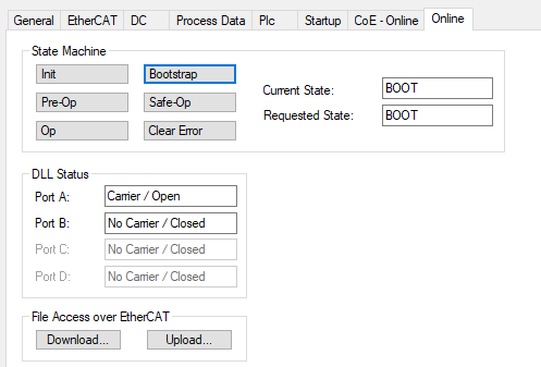
Once the state has changed to ‘BOOT’, Click ‘Download’ button.
Rename your EtherCAT application binary (.bin) as ECATFW__, and use this file as your new EtherCAT application firmware.
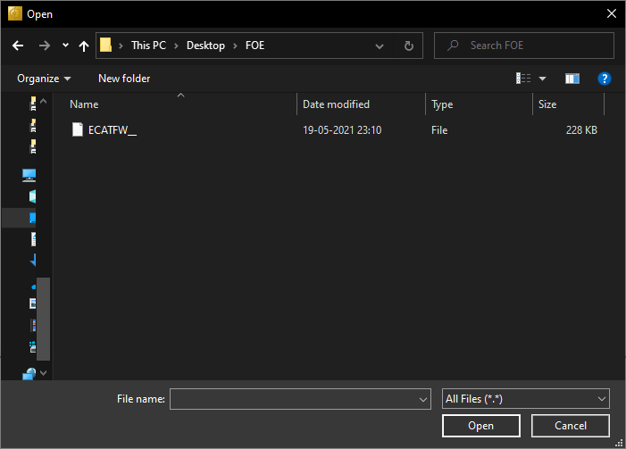
Locate the new firmware to be dowloaded click ‘Open’.
Click OK on the new dialog shown.
This will download the new firmware. The progress bar will show the status of download.
Once the download has finished, change the state back to “Init” by clicking ‘Init’ button. This will cause a reload of the application.
2.1.11. Enhanced Process Data Interface with EDMA support (only supported on AM4377/9)
EtherCAT Slave package includes an updated way to access to SyncManager
Process Data buffers from application side. Significant reduction in
access latency is observed with this mode. This uses the EDMA IP in
Sitara devices to offload the data buffer copy from the CPU and
currently only supported on AM4377/9 SoCs. To enable this mode, the
macro EDMA_LATENCY_ENHANCEMENT must be defined in the project. This
can be done by adding this macro to the
Project Properties->Build->GNU Compiler->Symbols->Define Symbols
option. Once enabled, the application and firmware switches to using
EDMA for buffer transfer.
2.1.11.1. Memory location of Buffer in application
The access latency is affected by the placement of buffer in the memory (eg:DDR, on-chip etc.). For the best results, please follow the below guidelines:
| Function | Buffer Size | Memory Location |
|---|---|---|
| Read | >10 bytes | DDR (cached) |
| Read | <=10 bytes | on-chip Memory (non-cached) |
| Write | any size | on-chip Memory (non-cached) |
The switching between DDR and on-chip memory of buffer is handled by the following macros (defined in tiescbsp.h)
- For RxPDO : If
RxPDO_CACHEDis set to 0 then it uses on-chip memory; if set to 1 it uses DDR memory - For TxPDO : If
TxPDO_CACHEDis set to 0 then it uses on-chip memory; if set to 1 it uses DDR memory
2.1.11.2. Improvement Results
Read and write access latency for sync manager buffers in Process Data was measure for this benchmarking. The below improvements are measured using the maximum access latency recorded on AM437x IDK.
| Process Data action | Max time in legacy application | Max time in Enhanced application | Improvement | Buffer Location |
|---|---|---|---|---|
| Read 253 bytes | 25.4 µs | 3.8 µs | 6.5x | DDR (cached) |
| Write 263 bytes | 6.7 µs | 1.9 µs | 3.5x | onChip RAM (non-Cached) |
| Read 5 bytes | 1.9 µs | 1.2 µs | 1.5x | onChip RAM (non-Cached) |
| Write 7 bytes | 2.4 µs | 0.7 µs | 3x | onChip RAM (non-Cached) |
2.1.12. Running EtherCAT Application in DC Mode
Following section shows how to run EtherCAT application in DC mode with TwinCAT master:
Launch TwinCAT XAE Shell and discover all the slaves in slave chain. Multiple slaves are required to make use of distributed clocks. Here, we used two TI-ESCs in the chain.
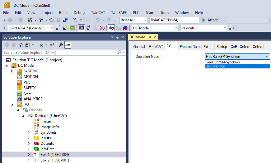
Choose DC Synchronization for all devices in the chain. Click on Box n (TIESC-*). Open the DC tab, and choose “DC-Synchron” option in Operation Mode. Do this for all slaves in the chain.
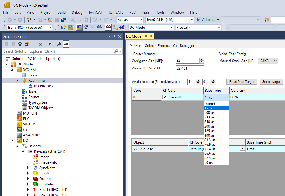
In Solution Explorer, go to TwinCAT project, Select SYSTEM > Real-Time. In the “Settings” tab, choose the desired Base Time. With compatible NIC cards, a base time of as low as 50 us can be chosen.
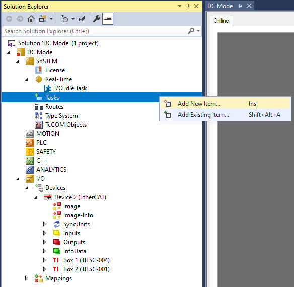
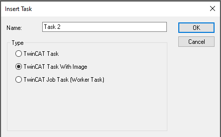
Right-click ON SYSTEM > Tasks. Click “Add New Item” on the pop-up menu. Select “TwinCAT Image with Task” in the next dialog box. Type a name for the task, and choose OK.
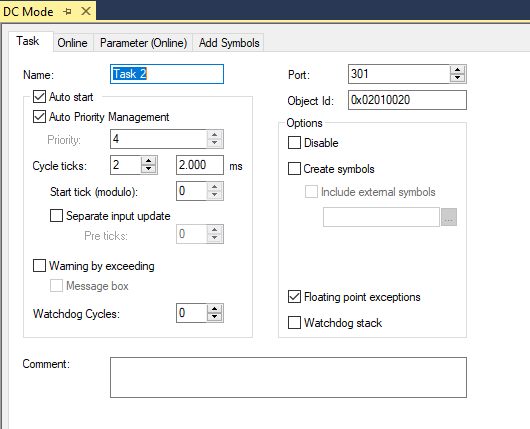
In the “Task” tab for the created task, select Auto Priority Management. Press OK in dialog box saying “Global Priority Management should be turned on”.
Choose “Auto start” for the task. Choose 2 cycle ticks’ frequency for the task.
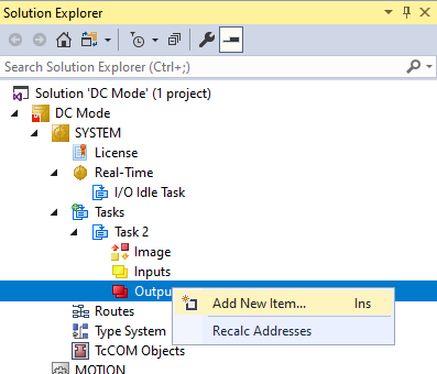
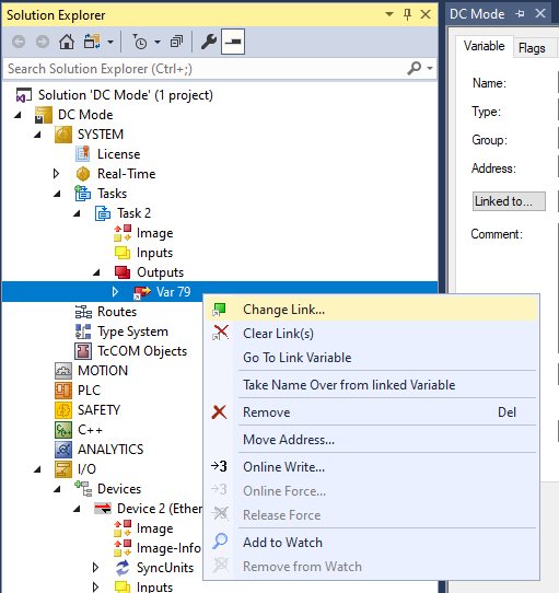
Add an output variable to the task. Right-click on [Task name] > Outputs, and choose “Add New Item”. You may choose default options for the variable.
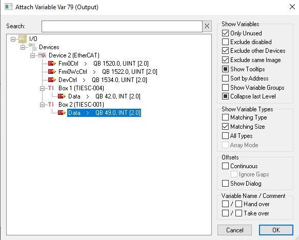
Link the variable to an output for the last slave in the chain. Right-click on [Variable name], and choose “Change Link…”.
Choose an output from the last slave. You may need to choose “All Types” in “Show Variable Types”.
You can launch into Run mode by clicking the
 “Activate Configuration” button on the toolbar.
Choose Yes to generate mapping after modifying configuration, click on OK to “Activate Configuration?”, and Yes to Restart in RUN mode.