2.3. PRU ICSS EtherCAT firmware API guide
- Introduction
- EtherCAT application - Software Architecture
- Firmware APIs
- Initialization of stack-firmware interface
- ESC Firmware Command API
- ESI EEPROM emulation support
- SyncManager properties management for TI ESC HAL
- SyncManager access and control APIs
- SyncManager Mailbox mode handling
- SyncManager Buffer mode handling
- ESC Register/Memory access - Special handling APIs
- bsp_read_byte
- bsp_read_word
- bsp_read_dword
- bsp_read
- bsp_read_byte_isr
- bsp_read_word_isr
- bsp_read_dword_isr
- bsp_pdi_post_read_indication
- bsp_pdi_write_indication
- HW_EscReadByteIsr
- HW_EscReadWordIsr
- HW_EscReadDWordIsr
- HW_EscReadIsr
- HW_EscWriteByte
- HW_EscWriteByteIsr
- HW_EscWriteWord
- HW_EscWriteWordIsr
- HW_EscWriteDWord
- HW_EscWriteDWordIsr
- HW_EscWrite
- HW_EscWriteIsr
- bsp_write_byte
- bsp_write_word
- bsp_write_dword
- bsp_write
- bsp_pruss_mdioreg_read
- bsp_pruss_mdioreg_write
- bsp_pruss_iepreg_read
- bsp_pruss_iepreg_write
- bsp_pruss_cmd_intfc_read_word
- bsp_pruss_cmd_intfc_write_word
- bsp_get_pdi_access_perm
- bsp_pdi_access_perm_word
- bsp_pdi_access_perm_dword
- bsp_pdi_access_perm_array
- bsp_get_pdi_read_access_fail_cnt
- bsp_get_pdi_write_access_fail_cnt
- PRU-ICSS MDIO host side APIs
- PRU-ICSS DIGIO host side APIs
- Spinlock APIs for concurrent Host/Firmware shared memory access
- System Time PDI controlled APIs
- Timer APIs for EtherCAT stack
- Mutex APIs for EtherCAT stack
- Interrupt management APIs for EtherCAT stack
- Misc APIs for SSC
- PRU firmware header mapping API
- Firmware Upgrade APIs for EtherCAT stack
- 110 PHY configuration APIs
- PRU-ICSS interrupt controller setup for EtherCAT firmware
- Firmware Update
- PRU-ICSS EtherCAT Register List
- Application Examples
2.3.1. Introduction
PRU-ICSS EtherCAT firmware implements EtherCAT slave controller layer2 functionality and provides EtherCAT ASIC like functionality integrated into AM335x/AM437x/AM57x/AM654x SOC with PRU-ICSS IP.
2.3.1.1. Purpose and Scope
Purpose of this document is to assist developers porting their EtherCAT slave stack to TI AM335x or AM437x or AM57x or AM654x SOCs.
2.3.1.2. Intended Audience
- System integrators using TI ESC in their products
- EtherCAT slave stack vendors to support TI ESC
2.3.1.3. Terms and Abbreviations
PRUSS : Programmable RealTime Unit Sub System
PRU-ICSS: Programmable RealTime Unit - Industrial Communication Sub System - PRUSS with industrial communication support
ESC : EtherCAT Slave Controller
ECAT : EtherCAT
PDI : Process Data Interface (Host interface to ESC)
HRT : High Real Time
SRT : Soft Real Time
2.3.1.4. References
- EtherCAT ESC datasheet Section I - Technology [1]
- EtherCAT ESC datasheet Section 2 - Register Description [2]
- AM335x TRM [3]
- PRU-ICSS Industrial Software [4]
- Beckhoff SSC documentation [5] available as part of ET9300 EtherCAT Slave Stack Code [6]
- EtherCAT slave implementation guide from ETG [7]
- SYS/BIOS PRUSS driver API [8]
2.3.2. EtherCAT application - Software Architecture
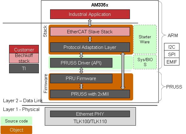
2.3.2.1. Procedure to kickoff ESC firmware
- Initialize memories (register protection, register reset values, EEPROM cache) and PRU-ICSS INTC
- Load ESC firmware into PRUs of PRU-ICSS
- Initialize the EtherCAT slave stack
- Start firmware
- Wait for AL Event Request and SYNC (in DC synchronous mode) interrupts from PRU and run EtherCAT stack main loop for handling mailbox and ESC state m/c
- Handle the events as needed - Note that this is handled by Beckhoff SSC (Eg:- PRU-ICSS-ETHERCAT-SLAVE sample application)or equivalent 3P stack
2.3.3. Firmware APIs
These APIs implement the key interface between ESC emulation firmware and EtherCAT stack. They are implemented in following source code files
TI h/w access layer to support EtherCAT slave using PRU-ICSS
sdk\protocols\ethercat_slave\ecat_appl\EcatStack\tiescbsp.c
sdk\protocols\ethercat_slave\include\tiescbsp.h
Wrapper APIs for SSC
sdk\protocols\ethercat_slave\ecat_appl\EcatStack\tieschw.c
sdk\protocols\ethercat_slave\include\tieschw.h
PRU_ICSS EtherCAT firmware headers
sdk\protocols\ethercat_slave\firmware\include\v1.0 : (AM335x)
sdk\protocols\ethercat_slave\firmware\include\v2.0 : (AM437x)
sdk\protocols\ethercat_slave\firmware\include\v2.1 : (AM57xx)
sdk\protocols\ethercat_slave\firmware\include\g_v1.0 : (AM654x)
APIs cover following important aspects.
- Stack - EtherCAT firmware IPC interface
- EEPROM emulation handling
- SyncManager properties management for TI ESC HAL
- SyncManager access and control APIs
- SyncManager Malibox mode support
- SyncManager Buffer mode support
- Special register/memory access handling (NOTE: registers are emulated in memory by firmware)
- PRU-ICSS MDIO host side APIs
- Spinlock APIs for concurrent Host/Firmware shared memory access
- System Time PDI controlled APIs
- Timer APIs for EtherCAT stack
- Mutex APIs for EtherCAT stack
- Interrupt Management APIs for EtherCAT stack
- PRU firmware header mapping API
- Firmware Upgrade APIs for EtherCAT stack
2.3.3.1. Initialization of stack-firmware interface
2.3.3.1.1. bsp_init
Function
void bsp_init(void);
Parameters
- none: none
- Return value: none
Description Initialize stack firmware interface. Setup PRU-ICSS interrupt controller for EtherCAT application. Initialize the PRU data memories. Setup register permissions by invoking bsp_esc_reg_perm_init. Load and start EtherCAT PRU firmware. Initialize EEPROM emulation Initialize command semaphore and bsp_mutex GateAll
2.3.3.1.2. bsp_esc_reg_perm_init
Function
void bsp_esc_reg_perm_init(void);
Parameters
- none: none
- Return value: none
Description Sets up register permissions for ECAT side access for TI ESC, if ENABLE_PDI_REG_PERMISSIONS is defined in tiescbsp.h, then this function also initializes register permissions for PDI side access from stack/application.
Note
ENABLE_PDI_REG_PERMISSIONS
This feature is not enabled by default in PRU-ICSS-ETHERCAT-SLAVE for optimizing memory and performance. TI_ESC has Onchip PDI interface where Host CPU has direct access to ESC registers as they are emulated using PRU_ICSS shared data memory.If ENABLE_PDI_REG_PERMISSIONS is defined and bsp_read/write_XXX are used by application for all register accesses then ONLY PDI access check is enforced. If application bypasses the use of bsp_read/write_xxx API (say HWREG to ESC register in PRU_ICSS memory), whole scheme won’t work. ENABLE_PDI_REG_PERMISSIONS is a software scheme and has overhead of 4KB data memory to maintain permission array and additional overhead of access check for every read/write to registers. ENABLE_PDI_REG_PERMISSIONS is enabled and bsp_read/write is enabled customer needs to set correct permissions in pdi_reg_perm_array, say for implementing vendor specific register for ESC to activate a host side feature.
Struct for register permission array
/* Starts at PRU1 DMEM @ 0x4a302000 */
typedef struct {
Uint8 reserved[1024];
Uint8 reg_properties[4096];
} t_register_properties;
2.3.3.1.3. bsp_start_esc_isr
Function
void bsp_start_esc_isr(void);
Parameters
- none: none
- Return value: none
Description Register IRQ handlers for various PRU-ICSS interrupts from firmware to host to clear corresponding events in PRU-ICSS INTC
2.3.3.1.4. bsp_exit
Function
void bsp_exit(void);
Parameters
- none: none
- Return value: none
Description Cleanup of TI ESC HAL
Delete command semaphore and bsp_mutex GateAll Flush the EEPROM cache to SPI flash if present Disable PRUs
2.3.3.1.5. bsp_set_pdi_wd_trigger_mode
Function
void bsp_set_pdi_wd_trigger_mode (Uint32 mode)
Parameters
- mode: PDI_WD_TRIGGER_RX_SOF/PDI_WD_TRIGGER_LATCH_IN/PDI_WD_TRIGGER_SYNC0/1_OUT
- Return value: none
Description Configure PDI WD trigger mode, PDI WD is triggered automatically by h/w on RX_SOF(port0/port1), latch0/1 input high, SYNC0/1 out high. PDI WD is also triggered whenever host sends a command to firmware. PDI WD may not expire if host stops sending commands to firmware alone, this will occur only if configured h/w events do not occur during WD period
2.3.3.2. ESC Firmware Command API
2.3.3.2.1. bsp_send_command_to_firmware
Function
void bsp_send_command_to_firmware(Uint32 command, Uint16 param1, Uint16 param2);
Parameters
- command: Command Id to be executed by ESC firmware
- param1: parameter1 corresponding to the command
- param2: parameter2 corresponding to the command
- Return value: none
Description Send command and parameters from stack to firmware to perform some action based on stack state or in response to AL event interrupt or SYNC interrupt from ESC
| Command | Id | Param1 | Param2 | Return Value | Remarks |
|---|---|---|---|---|---|
| CMD_DL_USE R_ACK_MBX_READ | 4 | address | length | NA | Indicate PDI side mailbox read completion to firmware |
| CMD_DL_USE R_ACK_MBX_WRITE | 5 | address | length | NA | Indicate PDI side mailbox write to firmware |
| CMD_DL_USE R_EEPROM_C MD_ACK | 6 | NA | NA | NA | Acknowledge EEEPROM emul ation command execution by ARM host stack |
| CMD_DL_USE R_READ_SYN C_STATUS | 7 | sync_sel | NA | NA | Indicate SYNC0/1 status register read by PDI to firmware |
| CMD_DL_USE R_READ_AL_CONTROL | 8 | NA | NA | NA | Indicate AL control register read by PDI to firmware |
| CMD_DL_USE R_WRITE_AL _STATUS | 9 | NA | NA | NA | Indicate AL status register write by PDI to firmware |
| CMD_DL_USE R_READ_PD_WD_STATUS | 10 | NA | NA | NA | Indicate PD watchdog status register read by PDI to firmware updating register status |
| CMD_DL_USE R_READ_SM_ACTIVATE | 11 | sm_index | NA | NA | Indicate SM activate register read by PDI to firmware |
| CMD_DL_USE R_WRITE_SM _PDI_CTRL | 12 | (sm_index<< 8) | pdi control reg value | NA | NA | Indicate SM PDI contr ol write to control SM from PDI to firmware |
| CMD_DL_USE R_READ_LAT CH_TIME | 13 | latch_sel | NA | NA | Indicate Latch0/1 time registest read by PDI to firmware |
| CMD_DL_USE R_READ_SYS TEM_TIME[ STRIKEOUT: ] | 14[STRIKEO UT: ] | NA[STRIKEO UT: ] | NA[STRIKEO UT: ] | NA[STRIKEO UT: ] | Indicate System Time register read by PDI to firmware |
| CMD_DL_USE R_CLEAR_AL _EVENT_LOW | 15 | event_mask | NA | NA | Clear events not set in event_mask in AL event request register |
| CMD_DL_USE R_SYSTIME_ PDI_CONTROL | 16 | reg_sel | NA | NA | Indicate to the firmware DC register update from PDI side |
Struct for host to PRU-ICSS command interface
/* Starts at PRU0 DMEM @ 0x4a300000 */
typedef struct {
Uint8 reserved1[0x90];
Uint32 system_time_low;
Uint32 system_time_high;
Uint8  sm_config_ongoing;
Uint8 reserved2[7];
Uint16 cmdlow;
Uint16 cmdlow_ack;
Uint16 param1low;
Uint16 param2low;
Uint16 resp1low;
Uint16 resp2low;
Uint8 reserved3[212];
t_sm_processdata sm_processdata[6];
} t_host_interface;
typedef struct {
Uint8 sm_buf_index;
Uint8 lock_state;
Uint16 addr;
} t_sm_processdata;
lock_state can have following values - access is protected using AM335x spinlock 2 to 7 for 6SMs (SM2 to SM7)
#define LOCK_PD_BUF_AVAILABLE_FOR_HOST 0 //Process data buffer is available for host access
#define LOCK_PD_BUF_HOST_ACCESS_START   1 //Host started access on process data
#define LOCK_PD_BUF_HOST_ACCESS_FINISH  2 //Host finished accessing process data
IMPORTANT NOTE on SUPPORT_CMDACK_POLL_MODE
EtherCAT firmware supports both poll mode and interrupt mode for command acknowledge. It is found that poll mode offers better latency in given scenarios but will waste CPU cycles busy waiting for command response from PRU. If you need to switch to command ack interrupt mode comment the define for SUPPORT_CMDACK_POLL_MODE in tiescbsp.h
2.3.3.3. ESI EEPROM emulation support
TI ESC follows 11.2.4 EEPROM Emulation of EtherCAT ESC datasheet Section I - Technology[9] from functional principle point of view. This is typically used in IP core based ESCs with non-volatile memory. Here Host CPU emulates all EEPROM operations (read/write/reload) using RAM and from EtherCAT master point of view, this is equivalent to I2C EEPROM managed by ESC.
ET1100
The EtherCAT master can invoke reloading the EEPROM content. In this case the Configured Station Alias 0x0012:0x0013 and PDI Control Bit 0x0140.9 (enhanced link detection) are not taken over, they are only taken over at the initial EEPROM loading after power-on or reset.
EtherCAT IP core
However The read data for a reload command (or the initial EEPROM loading) is reduced to the Configured Station Alias (0x0012:0x0013) and the Enhanced Link Detection Enables (0x0140[9], 0x0140[15:12]).
IP core uses scheme described in section 3.44.1 EEPROM emulation with IP Core.
There are some exceptions to how this implemented in TI ESC, compared to IP core.
TI ESC
Configured Station Alias, Enhanced Link Detection Enables and DL status. Bit2 is updated directly by HAL driver during initial EEPROM loading operation. Similar to ET1100. Exception to IP core.
PDI configuration (0x150:0x153) are not loaded during EEPROM reload/inital load. However this is programmable if customers want to make it similar to ET1100. We kept this way because PDI configuration programmability is limited for TI ESC. Similar to IP core.
Register Pulse Length of SyncSignals (0x0982:0x983) is updated from EEPROM ADR 0x0002 during reload operation. Similar to ET1100. Exception to IP core
IMPORTANT NOTE on EEPROM_SPI
SDK supports non-volatile storage for ESI EEPROM in ICE and IDK using SPI flash. However one can switch to volatile EEPROM (EEPROM in RAM and contents are not retained after power reset) for debugging purposes on ICE/IDK by undefining EEPROM_SPI in tiescbsp.h
2.3.3.3.1. bsp_eeprom_emulation_init
Function
void bsp_eeprom_emulation_init (void);
Parameters
- none: none
- Return value: none
Description Initialize the EEPROM cache in volatile RAM - if SPI flash has valid EEPROM load from SPI flash, otherwise load predefined EEPROM in application
2.3.3.3.2. bsp_eeprom_load_esc_registers
Function
Int32 bsp_eeprom_load_esc_registers (Int32 reload_flag);
Parameters
- reload_flag: If set reload command is being executed else first boot in progress
- Return value: 0: On successful load of registers -1: On CRC error
Description For loading ESC registers from EEPROM during first boot/reload after validating CRC
2.3.3.3.3. bsp_eeprom_emulation_reload
Function
Int32 bsp_eeprom_emulation_reload(void);
Parameters
- none: none
- Return value: 0: On successful load of registers -1: On CRC error
Description Perform reload operation after validating EEPROM CRC
2.3.3.3.4. HW_EepromReload
Function
UInt16 HW_EepromReload ();
Parameters
- none: none
- Return value: 0: On successful load of registers -1: On CRC error
Description Perform reload operation after validating EEPROM CRC, Wrapper API for SSC
2.3.3.3.5. bsp_eeprom_emulation_command_ack
Function
void bsp_eeprom_emulation_command_ack(void);
Parameters
- none: none
- Return value: none
Description Acknowledges EEPROM emulation command handling by stack to ESC firmware. Firmware performs necessary actions to update EEPROM status and AL event request registers in response to the command
2.3.3.3.6. bsp_eeprom_emulation_flush
Function
void bsp_eeprom_emulation_flush (void);
Parameters
- none: none
- Return value: none
Description Flush the EEPROM cache to non-volatile storage (say SPI flash) if available
2.3.3.3.7. bsp_get_eeprom_cache_base
Function
Uint8 *bsp_get_eeprom_cache_base(void);
Parameters
- none: none
- Return value: Pointer to volatile EEPROM cache start to the stack/application for EEPROM access
Description Return pointer to volatile EEPROM cache in TI ESC HAL for processing to access the EEPROM
2.3.3.3.8. bsp_set_eeprom_update_status
Function
void bsp_set_eeprom_update_status(Uint8 status);
Parameters
- status: Update the TI ESC HAL EEPROM update status - typically on EEPROM write detection from stack
- Return value: none
Description Indicate to TI ESC HAL whether EEPROM is written for flushing to non-volatile storage
2.3.3.3.9. bsp_get_eeprom_update_status
Function
Uint8 bsp_get_eeprom_update_status(void);
Parameters
- none: none
- Return value: EEPROM updated status
Description Read the EEPROM update status from TI ESC HAL - typically from low priority task periodically check EEPROM dirty status for flush
2.3.3.3.10. bsp_eeprom_emulation_exit
Function
void bsp_eeprom_emulation_exit (void);
Parameters
- none: none
- Return value: none
Description Call EEPROM flush on exit
2.3.3.4. SyncManager properties management for TI ESC HAL
These APIs indicate to TI ESC HAL layer changes in SM configuration in the h/w registers. Typically called from appropriate state transition handlers in application/stack
Struct for SM properties
typedef struct {
Uint16 physical_start_addr;
Uint16 length;
} t_sm_properties;
static t_sm_properties sm_properties[MAX_SYNC_MAN];
2.3.3.4.1. bsp_set_sm_properties
Function
void bsp_set_sm_properties (Uint8 sm, Uint16 address, Uint16 length);
Parameters
- sm: SyncManager index to set
- address: physical start address of SyncManager
- length: length of SyncManager
- Return value: none
Description Set the address, length info from register to TI ESC HAL layer. During INIT to PREOP transition in Mailbox mode. During SAFEOP to OP transition in Buffer mode
2.3.3.4.2. bsp_get_sm_properties
Function
t_sm_properties *bsp_get_sm_properties (Uint8 sm);
Parameters
- sm: SyncManager index to get properties from TI ESC HAL
- Return value: pointer to requested sm_properties array element in TI ESC HAL
Description Get the pointer to requested SM properties - used for Buffer/Mailbox read/write detection from Host PDI interface to indicate to the firmware
2.3.3.5. SyncManager access and control APIs
2.3.3.5.1. HW_EnableSyncManChannel
Function
void HW_EnableSyncManChannel(Uint16 channel)
Parameters
- channel: channel number (0:7)
- Return value: None
Description Enables SYNC manager channel from PDI
2.3.3.5.2. HW_DisableSyncManChannel
Function
void HW_DisableSyncManChannel(Uint16 channel)
Parameters
- channel: channel number (0:7)
- Return value: None
Description Disables SYNC manager channel from PDI
2.3.3.5.3. HW_GetSyncMan
Function
void *HW_GetSyncMan(Uint8 channel)
Parameters
- channel: channel number (0:7)
- Return value: Pointer to requested SM channel settings
Description Return SM properties like (address, length, control byte) to application from corresponding ESC registers
2.3.3.5.4. bsp_pdi_sm_config_ongoing
Function
Uint8 bsp_pdi_sm_config_ongoing (void)
Parameters
- None
- Return value: 0 : SM configuration finished Otherwise : SM configuration ongoing
Description Checks whether firmware has finished updating internal state for SM configuration change initiated by stack/PDI
2.3.3.6. SyncManager Mailbox mode handling
2.3.3.6.1. bsp_pdi_mbx_read_start
Function
void bsp_pdi_mbx_read_start(void);
Parameters
- none: none
- Return value: none
Description Indicates to the firmware that PDI side read from write mailbox has started
2.3.3.6.2. bsp_pdi_mbx_read_complete
Function
void bsp_pdi_mbx_read_complete(void);
Parameters
- none: none
- Return value: none
Description Indicates to the firmware that PDI side read from write mailbox has completed
2.3.3.6.3. bsp_pdi_mbx_write_start
Function
void bsp_pdi_mbx_write_start(void);
Parameters
- none: none
- Return value: none
Description Indicates to the firmware that PDI side write to read mailbox has started
2.3.3.6.4. bsp_pdi_mbx_write_complete
Function
void bsp_pdi_mbx_write_complete(void);
Parameters
- none: none
- Return value: none
Description Indicates to the firmware that PDI side write to read mailbox has completed
2.3.3.6.5. HW_EscReadMbxMem
Function
void HW_EscReadMbxMem(Uint8 * pdata, Uint16 address, Uint16 len)
Parameters
- pdata: Pointer to data array in application
- address: Mailbox address to read from PDI
- len: Length of data array in application
- Return value: None
Description Read ‘len’ bytes from ESC mailbox @ ‘address’ into application buffer pointed by ‘pdata’
Invokes
- bsp_get_sm_properties
- bsp_pdi_mbx_read_start
- bsp_read
- bsp_pdi_mbx_read_complete
2.3.3.6.6. HW_EscWriteMbxMem
Function
void HW_EscWriteMbxMem(Uint8 * pdata, Uint16 address, Uint16 len)
Parameters
- pdata: Pointer to data array in application
- address: Mailbox address to write from PDI
- len: Length of data array in application
- Return value: None
Description Write ‘len’ bytes from application buffer pointed by ‘pdata’ and copy to ESC mailbox @ ‘address’
Invokes
- bsp_get_sm_properties
- bsp_pdi_mbx_write_start
- bsp_write
- bsp_pdi_mbx_write_complete
2.3.3.7. SyncManager Buffer mode handling
2.3.3.7.1. bsp_get_process_data_address
Function
UINT16 bsp_get_process_data_address(Uint16 address, Uint16 len, Int16* p_sm_index);
Parameters
- address: SM buffer address for PDI side access
- len: SM buffer length for PDI side access
- Return value: Actual PDI address in memory
- p_sm_index: Matching SM index corresponding to address
Description Get the actual address of the buffer for PDI side read/write from host MPU in 3-buffer mode
2.3.3.7.2. bsp_process_data_access_complete
Function
void bsp_process_data_access_complete(Uint16 address, Uint16 len, Int16 sm_index);
Parameters
- address: SM buffer address for PDI side access
- len: SM buffer length for PDI side access
- sm_index: SM index of this process data buffer
- Return value: none
Description This API is invoked after PDI side completes read/write to PD address returned by bsp_get_process_data_address to indicate this to firmware for swapping buffers etc
2.3.3.8. ESC Register/Memory access - Special handling APIs
Ideally all register/ process data memory access shall use these APIs. This takes care of any special indication to firmware on register read/write etc.
2.3.3.8.1. bsp_read_byte
Function
Uint8 bsp_read_byte(Uint16 Address);
Parameters
- address: ESC address to read from PDI
- Return value: Value at address
Description Read a byte value at ‘Address’ from ESC memory - SM mailbox (single buffer) mapped or register area
Invokes
- bsp_pdi_mbx_read_complete
- bsp_pdi_post_read_indication
2.3.3.8.2. bsp_read_word
Function
Uint16 bsp_read_word(Uint16 Address);
Parameters
- address: ESC address to read from PDI
- Return value: Value at address
Description Read a 16-bit value at ‘Address’ from ESC memory - SM mailbox (single buffer) mapped or register area
Invokes
- bsp_pdi_mbx_read_complete
- bsp_pdi_post_read_indication
2.3.3.8.3. bsp_read_dword
Function
Uint32 bsp_read_dword(Uint16 Address);
Parameters
- address: ESC address to read from PDI
- Return value: Value at address
Description Read a 32-bit value at ‘Address’ from ESC memory - SM mailbox (single buffer) mapped or register area
Invokes
- bsp_pdi_mbx_read_complete
- bsp_pdi_post_read_indication
2.3.3.8.4. bsp_read
Function
void bsp_read(Uint8 *pdata, Uint16 address, Uint16 len);
Parameters
- pdata: Pointer to the array in application
- address: ESC address to read from PDI
- len : Number of bytes to read from ESC memory
- Return value: None
Description Read a byte array at ‘address’ from ESC memory
2.3.3.8.5. bsp_read_byte_isr
Function
Uint8 bsp_read_byte_isr(Uint16 Address);
Parameters
- address: ESC address to read from PDI
- Return value: Value at address
Description Read a byte value at ‘Address’ from ESC process data memory - SM buffer (3-buffer) mapped area
Invokes
- bsp_get_process_data_read_address
- bsp_send_command_to_firmware
2.3.3.8.6. bsp_read_word_isr
Function
Uint8 bsp_read_word_isr(Uint16 Address);
Parameters
- address: ESC address to read from PDI
- Return value: Value at address
Description Read a 16-bit value at ‘Address’ from ESC process data memory - SM buffer (3-buffer) mapped area
Invokes
- bsp_get_process_data_read_address
- bsp_send_command_to_firmware
2.3.3.8.7. bsp_read_dword_isr
Function
Uint32 bsp_read_dword_isr(Uint16 address);
Parameters
- address: ESC address to read from PDI
- Return value: Value at address
Description Read a 32-bit value at ‘Address’ from ESC process data memory - SM buffer (3-buffer) mapped area
Invokes
- bsp_get_process_data_read_address
- bsp_send_command_to_firmware
2.3.3.8.8. bsp_pdi_post_read_indication
Function
void bsp_pdi_post_read_indication(Uint16 address)
Parameters
- address: ESC address read from PDI
- Return value: None
Description Invoked after reading a register or mailbox buffer from PDI side
Handles following registers
- SM WD status
- AL control
- SYNC0/1 status
- SM Activate registers
- Latch0/1 time Postive/Negative edge
Also detects read mailbox start address access from PDI side
Invokes
- bsp_send_command_to_firmware
2.3.3.8.9. bsp_pdi_write_indication
Function
void bsp_pdi_write_indication(Uint16 address)
Parameters
- address: ESC address read from PDI
- Return value: None
Description Invoked after writing a register or mailbox buffer from PDI side
Handles following registers
- AL status
- SM PDI control registers
Also detects write mailbox start address access from PDI side
Invokes
- bsp_send_command_to_firmware
2.3.3.8.10. HW_EscReadByteIsr
Function macro
HW_EscReadByteIsr(ByteValue, Address)
Parameters
- Address: ESC address to read from PDI
- Return value: ByteValue at Address
Description Used by application to read process data byte from ESC memory
Invokes
- __HW_EscReadByteIsr
- bsp_get_process_data_address
- bsp_read_byte_isr
- bsp_process_data_access_complete
2.3.3.8.11. HW_EscReadWordIsr
Function macro
HW_EscReadWordIsr(WordValue, Address)
Parameters
- Address: ESC address to read from PDI
- Return value: WordValue at Address
Description Used by application to read process data word from ESC memory
Invokes
- __HW_EscReadWordIsr
- bsp_get_process_data_address
- bsp_read_word_isr
- bsp_process_data_access_complete
2.3.3.8.12. HW_EscReadDWordIsr
Function macro
HW_EscReadWordIsr(DWordValue, Address)
Parameters
- Address: ESC address to read from PDI
- Return value: DWordValue at Address
Description Used by application to read process data word from ESC memory
Invokes
- __HW_EscReadDWordIsr
- bsp_get_process_data_address
- bsp_read_word_isr
- bsp_process_data_access_complete
2.3.3.8.13. HW_EscReadIsr
Function
void HW_EscReadIsr(Uint8 * pdata, Uint16 address, Uint16 len)
Parameters
- pdata: Pointer to the data array to read
- address: ESC address to read from PDI
- Return value: None
Description Used by application to read process data output from ESC memory
Invokes
- bsp_get_process_data_address
- bsp_read
- bsp_process_data_access_complete
2.3.3.8.14. HW_EscWriteByte
Function
void HW_EscWriteByte(Uint8 bytevalue, Uint16 address)
Parameters
- address: ESC address to write from PDI
- bytevalue: Value to write
- Return value: None
Description Write a byte value at ‘address’ in ESC memory - SM mailbox (single buffer) mapped or register area
Invokes
- bsp_get_sm_properties
- bsp_write_byte
- bsp_pdi_mbx_write_complete
- bsp_pdi_write_indication
2.3.3.8.15. HW_EscWriteByteIsr
Function
void HW_EscWriteByteIsr(Uint8 bytevalue, Uint16 address)
Parameters
- address: ESC address to write from PDI
- bytevalue: Value to write
- Return value: None
Description Write a byte value at ‘address’ in ESC memory
Invokes
- bsp_get_process_data_address
- bsp_write_byte
- bsp_process_data_access_complete
2.3.3.8.16. HW_EscWriteWord
Function
void HW_EscWriteWord(Uint16 wordvalue, Uint16 address)
Parameters
- address: ESC address to write from PDI
- wordvalue: Value at address
- Return value: None
Description Write a 16-bit value to ‘address’ in ESC memory - SM mailbox (single buffer) mapped or register area
Invokes
- bsp_get_sm_properties
- bsp_write_word
- bsp_pdi_mbx_write_complete
- bsp_pdi_write_indication
2.3.3.8.17. HW_EscWriteWordIsr
Function
void HW_EscWriteWordIsr(Uint8 wordvalue, Uint16 address)
Parameters
- address: ESC address to write from PDI
- wordvalue: Value to write
- Return value: None
Description Write a word value at ‘address’ in ESC process data memory - SM buffer (3-buffer) mapped area
Invokes
- bsp_get_process_data_address
- bsp_write_word
- bsp_process_data_access_complete
2.3.3.8.18. HW_EscWriteDWord
Function
void HW_EscWriteDWord(Uint32 dwordValue, Uint16 Address)
Parameters
- address: ESC address to write from PDI
- dword value: Value at address
- Return value: None
Description Write a 32-bit value to ‘address’ in ESC memory - SM mailbox (single buffer) mapped or register area
Invokes
- bsp_get_sm_properties
- bsp_write_dword
- bsp_pdi_mbx_write_complete
- bsp_pdi_write_indication
2.3.3.8.19. HW_EscWriteDWordIsr
Function
void HW_EscWriteDWordIsr(Uint8 dwordvalue, Uint16 address)
Parameters
- address: ESC address to write from PDI
- dwordvalue: Value to write
- Return value: None
Description Write a 32-bit dword value at ‘address’ in ESC process data memory - SM buffer (3-buffer) mapped area
Invokes
- bsp_get_process_data_address
- bsp_write_dword
- bsp_process_data_access_complete
2.3.3.8.20. HW_EscWrite
Function
void HW_EscWrite(Uint8 * pdata, Uint16 address, Uint16 len)
Parameters
- pdata: Pointer to data array in application
- address: ESC address to read from PDI
- len: Length of data array in application
- Return value: None
Description Write ‘len’ bytes to ‘address’ in ESC memory from pdata
Invokes
- bsp_write
- bsp_pdi_write_indication
2.3.3.8.21. HW_EscWriteIsr
Function
void HW_EscWriteIsr(Uint8 * pdata, Uint16 address, Uint16 len);
Parameters
- pdata: Pointer to data array in application
- address: ESC address to read from PDI
- len: Length of data array in application
- Return value: None
- Description Write ‘len’ bytes to ‘address’ in ESC memory from
- pdata, used to copy process data input values from slave application to ESC memory for sending to EtherCAT master
Invokes
- bsp_get_process_data_address
- bsp_write
- bsp_process_data_access_complete
Following are mainly helper APIs used by memory access APIs in tieschw.c to implement register permission checks and firewall protection
2.3.3.8.22. bsp_write_byte
Function
void bsp_write_byte(Uint8 val, Uint16 address);
Parameters
- val: 8-bit value to write
- address: ESC address to write from PDI
- Return value: None
Description Write a byte value at ‘address’ in ESC memory
2.3.3.8.23. bsp_write_word
Function
void bsp_write_word(Uint16 val, Uint16 address);
Parameters
- val: 16-bit value to write
- address: ESC address to write from PDI
- Return value: None
Description Write a 16-bit value at ‘address’ in ESC memory
2.3.3.8.24. bsp_write_dword
Function
void bsp_write_dword( Uint32 val, Uint16 address);
Parameters
- val: 32-bit value to write
- address: ESC address to write from PDI
- Return value: None
Description Write a 32-bit value at ‘address’ in ESC memory
2.3.3.8.25. bsp_write
Function
void bsp_write(Uint8 *pdata, Uint16 address, Uint16 len);
Parameters
- pdata: Pointer to byte array in application
- address: ESC address to write from PDI
- len: Length of data
- Return value: None
Description Write ‘len’ bytes from pdata to ‘address’ in ESC memory
2.3.3.8.26. bsp_pruss_mdioreg_read
Function
Uint32 bsp_pruss_mdioreg_read (Uint32 regoffset);
Parameters
- val: 32-bit value to read from PRU-ICSS MDIO
- regoffset: PRU-ICSS MDIO register offset
- Return value: None
Description Read a 32-bit value from PRU-ICSS MDIO register at ‘regoffset’
2.3.3.8.27. bsp_pruss_mdioreg_write
Function
void bsp_pruss_mdioreg_write (Uint32 val, Uint32 regoffset);
Parameters
- val: 32-bit value to write to PRU-ICSS MDIO
- regoffset: PRU-ICSS MDIO register offset
- Return value: None
Description Write a 32-bit value at PRU-ICSS MDIO register at ‘regoffset’
2.3.3.8.28. bsp_pruss_iepreg_read
Function
Uint32 bsp_pruss_iepreg_read (Uint32 regoffset);
Parameters
- val: 32-bit value to read from PRU-ICSS IEP
- regoffset: PRU-ICSS IEP register offset
- Return value: None
Description Read a 32-bit value from PRU-ICSS IEP register at ‘regoffset’
2.3.3.8.29. bsp_pruss_iepreg_write
Function
void bsp_pruss_iepreg_write (Uint32 val, Uint32 regoffset);
Parameters
- val: 32-bit value to write to PRU-ICSS IEP
- regoffset: PRU-ICSS IEP register offset
- Return value: None
Description Write a 32-bit value at PRU-ICSS IEP register at ‘regoffset’
2.3.3.8.30. bsp_pruss_cmd_intfc_read_word
Function
Uint16 bsp_pruss_cmd_intfc_read_word (volatile Uint16 *ptr);
Parameters
- ptr: PRU-ICSS command interface pointer
- Return value: 16-bit value read
Description Read a 16-bit value from PRU-ICSS IEP command interface
2.3.3.8.31. bsp_pruss_cmd_intfc_write_word
Function
void bsp_pruss_cmd_intfc_write_word (Uint16 val, volatile Uint16 *ptr);
Parameters
- val: 16-bit value to write
- ptr: Pointer to Host - PRU-ICSS command interface in PRU-ICSS data memory
- Return value: None
Description Write a 16-bit value at PRU-ICSS command interface pointer
2.3.3.8.32. bsp_get_pdi_access_perm
Function
inline Uint8 bsp_get_pdi_access_perm(Uint16 address, Uint8 access);
Parameters
- address: PDI Register address
- access: Permission to be checked ( Read, Write, Read&Write )
- Return value: 1 if the register has the requested permission, 0 if otherwise
Description Checks if the PDI register [byte] has the requested access permission and returns the result
2.3.3.8.33. bsp_pdi_access_perm_word
Function
inline Uint8 bsp_pdi_access_perm_word(Uint16 address, Uint8 access);
Parameters
- address: PDI Register start address
- access: Permission to be checked ( Read, Write, Read&Write )
- Return value: 1 if the register has the requested permission, 0 if otherwise
Description Checks if the PDI register [Two bytes] has the requested access permission and returns the result
2.3.3.8.34. bsp_pdi_access_perm_dword
Function
inline Uint8 bsp_pdi_access_perm_dword(Uint16 address, Uint8 access);
Parameters
- address: PDI Register start address
- access: Permission to be checked ( Read, Write, Read&Write )
- Return value: 1 if the register has the requested permission, 0 if otherwise
Description Checks if the PDI registers (Four bytes) has the requested access permission and returns the result
2.3.3.8.35. bsp_pdi_access_perm_array
Function
inline Uint8 bsp_pdi_access_perm_array(Uint16 address, Uint8 access, Uint16 size);
Parameters
- address: PDI Register start address
- access: Permission to be checked ( Read, Write, Read&Write )
- size: Number of register bytes
- Return value: 1 if the register has the requested permission, 0 if otherwise
Description Checks if all PDI registers starting from ‘address’ has the requested access permission and returns the result
2.3.3.8.36. bsp_get_pdi_read_access_fail_cnt
Function
Uint32 bsp_get_pdi_read_access_fail_cnt();
Parameters
- None
- Return value: Number of denied PDI register read attempts
Description Provides the number of times the read request was denied
2.3.3.8.37. bsp_get_pdi_write_access_fail_cnt
Function
Uint32 bsp_get_pdi_write_access_fail_cnt();
Parameters
- None
- Return value: Number of denied PDI register write attempts
Description Provides the number of times the write request was denied
2.3.3.9. PRU-ICSS MDIO host side APIs
2.3.3.9.1. bsp_pruss_mdio_init
Function
Int16 bsp_pruss_mdio_init (t_mdio_params *pmdio_params);
Parameters
- pmdio_params: Pointer to parameter structure of PRU-ICSS MDIO initialization
- pmdio_params->clkdiv: MDIO clkdiv. MDIO clock = 200/(clkdiv+1)
- pmdio_params->addr0: Address of the PHY hooked to PRU-ICSS MII0
- pmdio_params->addr1: Address of the PHY hooked to PRU-ICSS MII1
- pmdio_params->link0pol: LINK_MII signal polarity of PHY hooked to PRU-ICSS MII0
- pmdio_params->link1pol: LINK_MII signal polarity of PHY hooked to PRU-ICSS MII1
- pmdio_params->enhancedlink_enable: Enable enhanced link detection using MII RXLINK and TLK110 enhanced link detection features
Struct for MDIO initialization parameters
typedef struct {
 Uint16 clkdiv;
 Uint8 addr0;
 Uint8 addr1;
 Uint8 link0pol; //1: Active Low 0: Active High
 Uint8 link1pol; //1: Active Low 0: Active High
 Uint8 enhancedlink_enable;
} t_mdio_params;
- Return value: none
Description Initializes PRU-ICSS MDIO for EtherCAT firmware to communicate with PHYs. Must be called after powering on PRU-ICSS domain and before PRU firmware is loaded and executed on both PRUs.
The setting of Link polarity parameters link0pol and link1pol are determined by MDIOLINK Register when enhanced link detection is enabled.
MDIOLINK Register is updated after a read of the Generic Status Register of a PHY. Typically the bit is set if the PHY with the corresponding address has link and the PHY acknowledges the read transaction. The bit is reset if the PHY indicates it does not have link or fails to acknowledge the read transaction. Writes to the register have no effect. In addition, the status of the two PHYs specified in the MDIOUSERPHYSELn registers can be determined using the MLINK input pins. This is determined by the LINKSEL bit in the MDIOUSERPHYSELn register.
The LINKSEL (Link status determination select) bit in MDIOUSERPHYSELn register determines link status using the MLINK pin by setting to 1. Default value is 0 which implies that the link status is determined by the MDIO state machine.
pr1_mii0_rxlink/pr1_mii1_rxlink pin of PRU-ICSS, which connects to PHY LED_LINK/LED_SPEED pin is connected as MLINK signal to MDIO and in enhanced link detection mode MDIO directly uses MLINK signal to detect the link status from PHY. MDIO state machine based detection is very slow - slow serial link for messaging from MDIO controller to PHYs - this typically takes around 200-250us for PHYs. MLINK/mii_rxlink detection as fast as PHY can toggle this link – with special settings TI PHYs can detect link within 10us, depending on the PHY strap settings link polarity will be different for different boards and needs to adjusted per board by reading MDIOLINK register, also insure to set PHY LED_LINK/LED_SPEED mode as ‘LINK_OK’ in stead of ‘RX/TX Activity’ to prevent link detection failure from RX/TX activity.
2.3.3.9.2. bsp_pruss_mdio_phy_read
Function
Int16 bsp_pruss_mdio_phy_read (Uint8 phyaddr, Uint8 regoffset, Uint16 *regval);
Parameters
- phyaddr: Select the PHY to read using PHY address
- regoffset: Register offset in PHY to read
- regval: Pointer to the variable to hold the register value read
- Return value: 0 : Success -1 : MDIO access error
Description API to read PHY register via PRU-ICSS MDIO
2.3.3.9.3. bsp_pruss_mdio_phy_write
Function
Int16 bsp_pruss_mdio_phy_write (Uint8 phyaddr, Uint8 regoffset, Uint16 regval);
Parameters
- phyaddr: Select the PHY to write using PHY address
- regoffset: Register offset in PHY to read
- regval: Value to write to the PHY register
- Return value: 0 : Success -1 : MDIO access error
Description API to write PHY register via PRU-ICSS MDIO
2.3.3.9.4. bsp_pruss_mdio_phy_link_state
Function
Uint8 bsp_pruss_mdio_phy_link_state (Uint8 phyaddr); //Till 1.1.0.4
Function
Uint32 bsp_pruss_mdio_phy_link_state (Uint8 phyaddr); //From 1.1.0.5
Parameters
- phyaddr: Select the PHY for link status
- Return value: 0: Link Down Otherwise: Link Up
Description Get the link status for selected PHY, this API considers MII_link signal polarity differences and recommended when TIESC_MDIO_RX_LINK_ENABLE is enabled for enhanced link detection
2.3.3.10. PRU-ICSS DIGIO host side APIs
These APIs are added to support PDI ISR output to external SOC pin (via one of the 8 PRU-ICSS digio outputs). However they can be used as generic GPIO pin from host side. PRU side access is obviously way faster. PDI ISR pin can be selected via vendor specific register @ 0xE0A
2.3.3.10.1. void bsp_set_digio_sw_dataout_enable (void)
Function
void bsp_set_digio_sw_dataout_enable (void);
Parameters
- none
- Return value: none
Description Configure digio for sw controlled dataout mode
2.3.3.10.2. void bsp_set_digio_out (Uint8 num)
Function
void bsp_set_digio_out (Uint8 num);
Parameters
- num: digital output selection (num=0..7)
- Return value: none
Description Set selected digital output pin
2.3.3.10.3. void bsp_clear_digio_out (Uint8 num)
Function
void bsp_clear_digio_out (Uint8 num);
Parameters
- num: digital output selection (num=0..7)
- Return value: none
Description Clear selected digital output pin
2.3.3.12. System Time PDI controlled APIs
Enable DC feature of system time compensation via PDI interface instead of ECAT interface for synchronizing two independent EtherCAT networks
2.3.3.12.1. bsp_pdi_write_system_time
Function
void bsp_pdi_write_system_time (Uint32 systime);
Parameters
- systime: 32-bit system time value
- Return value: none
Description Write 32-bit system time to firmware to trigger drift compensation
2.3.3.12.2. bsp_pdi_write_system_timeoffset
Function
void bsp_pdi_write_system_timeoffset (unsigned long long systime)
Parameters
- systime: 64-bit system time offset value
- Return value: none
Description Write 64-bit System Time Offset (0x920) register and indicate to the firmware
2.3.3.12.3. bsp_pdi_write_systime_delay
Function
void bsp_pdi_write_systime_delay(Uint32 systime);
Parameters
- systime: 32-bit system time delay value
- Return value: none
Description Write 32-bit System Time Delay (0x928) register
2.3.3.12.4. bsp_pdi_write_filterconfig
Function
void bsp_pdi_write_filterconfig (Uint16 speedcount_start, Uint8 speedcount_filtdepth, Uint8 systime_filtdepth)
Parameters
- speedcount_start: 16-bit Speed Counter Start value at (0x930)
- speedcount_filtdepth: Filter depth 0-16 (0x935)
- systime_filtdepth: Filter depth 0-16 (0x934)
- Return value: none
Description Initialize the System Time and SpeedCounter Diff filters from PDI side
2.3.3.12.5. bsp_pdi_latch0_control
Function
void bsp_pdi_latch0_control(PRUICSS_Handle pruIcssHandle, Uint8 val)
Parameters
- val: Bitmask to enable singleshot mode [Bit0 : posedge Bit1: negedge]
- Return value: none
Description Enable latch single shot/continuous mode for Latch0 via PDI interface If bit is clear latch will be configured in continuous mode
2.3.3.12.6. bsp_pdi_latch1_control
Function
void bsp_pdi_latch1_control(PRUICSS_Handle pruIcssHandle, Uint8 val)
Parameters
- val: Bitmask to enable singleshot mode [Bit0 : posedge Bit1: negedge]
- Return value: none
Description Enable latch single shot/continuous mode for Latch1 via PDI interface
If bit is clear latch will be configured in continuous mode
2.3.3.13. Timer APIs for EtherCAT stack
IMPORTANT NOTE on USE_ECAT_TIMER
There are 2 options for time base. If USE_ECAT_TIMER is defined in tiescbsp.h, ESC timebase is used otherwise SYS/BIOS API “Timestamp_get32” is used. For “Timestamp_get32” make sure to select the same in SYS/BIOS config file
2.3.3.13.1. bsp_get_timer_register
Function
Uint32 bsp_get_timer_register(void);
Parameters
- none
- Return value: 32-bit time elapsed since last call to bsp_clear_timer_register
Description Returns the time difference from last call of “bsp_clear_timer_register” to this “bsp_get_timer_register”. handles overflow
2.3.3.13.2. bsp_clear_timer_register
Function
void bsp_clear_timer_register(void);
Parameters
- none
- Return value: none
Description Update the time when “bsp_clear_timer_register” last invoked.This is a wrapper API used by SSC. Implemented using SYS/BIOS API
2.3.3.13.3. HW_GetTimer
Function
unsigned int HW_GetTimer()
Parameters
- none
- Return value: 32-bit time elapsed since last call to HW_ClearTimer
Description Returns the time difference from last call of “HW_ClearTimer” to this “HW_GetTimer”. handles overflow. This is a wrapper API used by SSC.
2.3.3.13.4. HW_ClearTimer
Function
void HW_ClearTimer(void);
Parameters
- none
- Return value: none
Description Update the time when “HW_ClearTimer” last invoked.This is a wrapper API used by SSC.
2.3.3.13.5. bsp_get_local_sys_time
Function
void bsp_get_local_sys_time(Uint32 *systime_low, Uint32 *systime_high);
Parameters
- Pointers to store system time low (32-bit LSW) and system time high (32-bit MSW)
- Return value: 64-bit local system time from EtherCAT slave (nanosec resolution)
Description Return EtherCAT time base for application use
2.3.3.13.6. bsp_get_latch0_posedge_time
Function
void bsp_get_latch0_posedge_time (Uint32 *systime_low, Uint32 *systime_high)
Parameters
- Pointers to store latch0 posedge low (32-bit LSW) and latch0 posedge high (32-bit MSW)
- Return value: 64-bit latch0 posedge timestamp from EtherCAT slave (nanosec resolution)
Description Return latch0 posedge timestamp for application use
2.3.3.13.7. bsp_get_latch1_posedge_time
Function
void bsp_get_latch1_posedge_time (Uint32 *systime_low, Uint32 *systime_high)
Parameters
- Pointers to store latch1 posedge low (32-bit LSW) and latch1 posedge high (32-bit MSW)
- Return value: 64-bit latch1 posedge timestamp from EtherCAT slave (nanosec resolution)
Description Return latch1 posedge timestamp for application use
2.3.3.13.8. bsp_get_latch0_negedge_time
Function
void bsp_get_latch0_negedge_time (Uint32 *systime_low, Uint32 *systime_high)
Parameters
- Pointers to store latch0 negedge low (32-bit LSW) and latch0 negedge high (32-bit MSW)
- Return value: 64-bit latch0 negedge timestamp from EtherCAT slave (nanosec resolution)
Description Return latch0 negedge timestamp for application use
2.3.3.13.9. bsp_get_latch1_negedge_time
Function
void bsp_get_latch1_negedge_time (Uint32 *systime_low, Uint32 *systime_high)
Parameters
- Pointers to store latch1 negedge low (32-bit LSW) and latch1 negedge high (32-bit MSW)
- Return value: 64-bit latch1 negedge timestamp from EtherCAT slave (nanosec resolution)
Description Return latch1 negedge timestamp for application use
2.3.3.14. Mutex APIs for EtherCAT stack
2.3.3.14.1. bsp_global_mutex_lock
Function
void bsp_global_mutex_lock (void);
Parameters
- none
- Return value: none
Description Critical section enter API using semaphore/mutex/interrupt disable primitives from RTOS. Implemented using SYS/BIOS API “GateAll_enter” in SDK
2.3.3.14.2. bsp_global_mutex_unlock
Function
void bsp_global_mutex_unlock (void);
Parameters
- none
- Return value: none
Description Critical section leave API using semaphore/mutex/interrupt enable primitives from RTOS. Implemented using SYS/BIOS API “GateAll_leave” in SDK
2.3.3.15. Interrupt management APIs for EtherCAT stack
2.3.3.15.1. HW_ResetALEventMask
Function
void HW_ResetALEventMask(Uint16 intMask);
Parameters
- intMask: AL event mask
- Return value: none
Description Reset AL event mask in AL event mask register (0x204), write AND of intMask and current AL event mask value to AL event mask register
Invokes
- HW_EscReadWord
- HW_EscWriteWord
2.3.3.15.2. HW_SetALEventMask
Function
void HW_SetALEventMask(Uint16 intMask);
Parameters
- intMask: AL event mask
- Return value: none
Description Set AL event mask in AL event mask register (0x204), write OR of intMask and current AL event mask value to AL event mask register
Invokes
- HW_EscReadWord
- HW_EscWriteWord
2.3.3.15.3. HW_GetALEventMask
Function
Uint16 HW_GetALEventMask(void);
Parameters
- None
- Return value: Current AL event mask
Description Return the current AL event mask used in Stack
2.3.3.15.4. HW_EcatIsr or PDI_Isr
Function
void PDI_Isr/HW_EcatIsr (void);
Parameters
- None
- None
Description PDI IRQ handler in the EtherCAT slave stack
2.3.3.15.5. Sync0_Isr
Function
void Sync0_Isr (void);
Parameters
- None
- None
Description SYNC0 IRQ handler in the EtherCAT slave stack
2.3.3.15.6. Sync1_Isr
Function
void Sync1_Isr (void);
Parameters
- None
- None
Description SYNC1 IRQ handler in the EtherCAT slave stack
2.3.3.16. Misc APIs for SSC
2.3.3.16.1. HW_Init
Function
Uint8 HW_Init(void);
Parameters
- none
- Return value: Zero
Description Initializes EtherCAT slave interface by calling bsp_init. Wait for firmware to be ready. Reset AL event mask. Register PDI and SYNC interrupt handlers. Disables all SyncManagers
Invokes
- bsp_init
- HW_EscReadWord
- HW_ResetALEventMask
- HW_DisableSyncManChannel
2.3.3.16.2. HW_Release
Function
void HW_Release(void);
Parameters
- none
- Return value: none
Description Wrapper API for bsp_exit, delete RTOS resources, flush ESI EEPROM, disable PRUs
Invokes
- bsp_exit
2.3.3.16.3. HW_RestartTarget
Function
void HW_RestartTarget(void);
Parameters
- none
- Return value: none
Description Perform the WARM RST of AM335x
IMPORTANT NOTE
This will result in application state to be lost and disrupt ongoing EtherCAT communication. Typical use is to upgrade the EtherCAT firmware
2.3.3.16.4. HW_SetLed
Function
void HW_SetLed(Uint8 RunLed, Uint8 ErrLed);
Parameters
- RunLed: 1 : on 0 : off
- ErrLed: 1 : on 0 : off
- Return value: none
Description API to control onboard Run and ERR LEDs
Invokes
- set_run_led
- reset_run_led
- set_error_led
- reset_error_led
2.3.3.17. PRU firmware header mapping API
2.3.3.17.1. bsp_set_pru_firmware
ARM Applications running on TI AM335x ICE develoment board can load firmwares for PRUs from SPI flash using binary files or from header files built as part of these applications. This API is mandatory to specify the PRU firmware array address to application if firmware header files are used.
Function
void bsp_set_pru_firmware(Uint32* frameProc,Uint32 frameProcLen,
               Uint32* hostProc,Uint32 hostProcLen);
Parameters
- frameProc - Pointer to a buffer containing HRT PRU firmware (ecat_frame_handler_bin.h)
- frameProcLen - Size of the HRT PRU firmware
- hostProc - Pointer to a buffer containing SRT PRU firmware (ecat_host_interface_bin.h)
- hostProcLen - Size of the SRT PRU firmware
- Return value: none
Description This function internally sets the location from which PRU firmwares can be loaded.If this API is not called, Application will try to load PRU firmwares from SPI flash.
2.3.3.18. Firmware Upgrade APIs for EtherCAT stack
EtherCAT application supports runtime firmware upgrade. This functionality can be enabled/disabled by defining/undefining ENABLE_ONLINE_FIRMWARE_UPGRADE macro in tiesbsp.h
2.3.3.18.1. bsp_start_fw_download
Function
void bsp_start_fw_download(Uint32 password);
Parameters
- password: password received from master
- Return value: none
Description Called by EtherCAT stack when a firmware download command is received from EtherCAT master
2.3.3.18.2. bsp_store_fw_data
Function
void bsp_store_fw_data(Uint16 *pData,Uint16 Size);
Parameters
- pData: Pointer to data buffer
- Size: Number of bytes received
- Return value: none
Description Stores the received data as part of firmware download from EtherCAT master. This may get called multiple times during firmware download. This function performs SPI flash writes for every 256-bytes received from master.
2.3.3.18.3. bsp_boot_2_init_handler
Function
void bsp_boot_2_init_handler();
Parameters
- None
- Return value: none
Description Initiates the Application restart when EtherCAT state is changed from BOOTSTRAP to INIT after application update using FoE protocol. This function performs SPI flash write for remaining bytes in receive data buffer once firmware download is finished by EtherCAT master
2.3.3.19. 110 PHY configuration APIs
These APIs are used to configure Texas Instruments TLK110 phy and variants.
Please note that these API are PHY specific and are only for the use of TLK105/106/110 Phys.
2.3.3.19.1. bsp_tlk110_init
Function
void bsp_tlk110_init(Uint8 phy0addr, Uint8 phy1addr, Uint8 enhancedlink_enable);
Parameters
- phy0addr: Phy address of port0
- phy1addr: Phy address of port1
- enhancedlink_enable: Fast link detect (enhanced link detection) enable/disable flag
- Return value: none
Description This API configures port0 and port1 phys for enhanced link detection, enable RXERR detection during IDLE, disable detection of transmit error in odd-nibble boundary (for odd nibble insertion) and fast RXDV detection. This is called only during initialization.
2.3.3.19.2. bsp_tlk110_configure_automdix
Function
void bsp_tlk110_configure_automdix(Uint8 phy0addr, Uint8 phy1addr);
Parameters
- phy0addr: Phy address of port0
- phy1addr: Phy address of port1
- Return value: none
Description This API enables port0 and port1 phys with auto-negotiation and auto MDIX capability.
2.3.4. PRU-ICSS interrupt controller setup for EtherCAT firmware
PRU-ICSS subsystem has got a dedicated INTC which actually takes various system events and map it to PRUs and Host processor (max 8 interrupts).
SYS_EVT_16-31 is reserved for generating interrupts for IPC with Host and PRU-ICSS
For EtherCAT, INTC initialization and setup is performed by TI ESC HAL driver on ARM side using PRU-ICSS driver API - “prussdrv_pruintc_init”
Various ICSS events of interest to EtherCAT firmware and their mapping to different SOC cores (A8/PRU0/PRU1) are defined below
sdk/protocols/ethercat/ecat_appl/src/tiesc_pruss_intc_mapping.h
IMPORTANT NOTE
Users shall not modify the above header as it is tightly coupled with Industrial fieldbus protocol implemented using PRU-ICSS
EtherCAT firmware and stack/application uses following interrupts
Stack/application interrupts
SYNC0_OUT_EVENT -> PRU_EVTOUT0 (PRU2ARM interrupt0) - Used in DC mode for syncing the host app SYNC1_OUT_EVENT -> PRU_EVTOUT1 (PRU2ARM interrupt1) - Used in DC mode for syncing the host app PRU2ARM_EVENT0 -> PRU_EVTOUT3 (PRU2ARM interrupt3) - AL event interrupt to host stack
Host-PRU-ICSS IPC interrupts
ARM2PRU_EVENT0 -> PRU1 (Command high indication to SRT PRU which does host command handling) ARM2PRU_EVENT1 -> PRU1 (Command low indication to SRT PRU which does host command handling) PRU2ARM_EVENT1 -> PRU_EVTOUT2 (PRU2ARM interrupt2) - Generated from PRU for acknowledging the command high PRU2ARM_EVENT2 -> PRU_EVTOUT4 (PRU2ARM interrupt4) - Generated from PRU for acknowledging the command low
Note
Configuring PRU-ICSS INTC for TI ESC HAL - HW_Init() does all this when invoked by application
tpruss_intc_initdata pruss_intc_initdata = PRUSS_INTC_INITDATA;
prussdrv_pruintc_init(&pruss_intc_initdata);
//load PRU firmware
bsp_start_esc_isr();
The above API sets up interrupt mapping for EtherCAT firmware and stack in PRUSS-INTC. Stack needs to register for interrupts, it needs to handle now
if ENABLE_PDI_TASK and ENABLE_SYNC_TASK are defined in tiescbsp.h, PDI and SYNC0 ISR processing will happen in SYS/BIOS task context. Helps to reduce processing in interrupt context.
In this mode, PRU-ICSS interrupt handler (implemented in sdk\os_drivers\src\pruss_drv.c) will post a semaphore and application task will wait on semaphore to handle those interrupts.
/**
* \brief  This function Registers an Interrupt Handler for an ARM Side event.\n
*
* \param   pruEvtoutNum   The ARM side event number.\n
* \param    waitEnable     Flag specifying whether application can wait on this interrupt
*                          using PRUSSDRVPruWaitEvent function
* \param   irqHandler     Pointer to a function which will be called on interrupt.\n
*
* \return  0 in case of successful registration, -1 otherwise. \n
*/

PRUSSDRVRegisterIrqHandler(HOST_AL_EVENT, 1, &EcatIsr);
PRUSSDRVRegisterIrqHandler(HOST_SYNC0_EVENT, 1, &Sync0Isr);
/**
* \brief  This function waits for a Syatem event to happen \n
*
* \param   eventnum   The AINTC Event number.\n
*
* \return  0 in case of successful transition, -1 otherwise. \n
*/
PRUSSDRVPruWaitEvent(HOST_AL_EVENT);
PRUSSDRVPruWaitEvent(HOST_SYNC0_EVENT);
Application needs to implement tasks for ISR processing, refer to sdk\protocols\ethercat_slave\ecat_appl\EcatStack\tiescappl.c for more details
For example:
void HW_EcatIsr(void)
{
/* get the AL event register */
PDI_Isr();
}
Void PDItask(UArg arg1, UArg arg2)
{
while(1)
{
  PRUSSDRVPruWaitEvent(HOST_AL_EVENT);
  /* ISR processing */
  HW_EcatIsr();
}
}
Void Sync0task(UArg arg1, UArg arg2)
{
while(1)
{
  PRUSSDRVPruWaitEvent(HOST_SYNC0_EVENT);
  //Do sync0 event handling
  Sync0_Isr();
}
}
if ENABLE_PDI_TASK and ENABLE_SYNC_TASK are NOT defined in tiescbsp.h, PDI and SYNC0 ISR processing will happen in SYS/BIOS HWI context. This is similar to SSC architecture.
PRU-ICSS interrupt handler (implemented in sdk\os_drivers\src\pruss_drv.c) won’t post a semaphore as there is no task required to handle those interrupts.
PRUSSDRVRegisterIrqHandler(HOST_AL_EVENT, 0, &EcatIsr); //Note that second argument is zero
PRUSSDRVRegisterIrqHandler(HOST_SYNC0_EVENT, 0, &Sync0Isr); //Note that second argument is zero
Directly call PDI ISR handling function (PDI_Isr) of EtherCAT stack from EcatIsr function in tiescbsp.c
Directly call SYNC0 ISR handling function (Sync0_Isr) of EtherCAT stack from Sync0Isr function in tiescbsp.c
2.3.5. Firmware Update
PRU Firmware is available in header file format and binary file format as part of SDK releas in the folder sdk\protocols\ethercat\firmware.
To update the firmware, one needs to rebuild the EtherCAT sample application with new version of headers before flashing the application.
Flashing the standalone firmware is also supported in SDK, refer to IRAM build configuration (EXEC_FROM_IRAM)and SDK user guide for more information.
Firmware revision is available in ESC registers shown below
Revision (0x0001)
1: For PRUSS v2 h/w supporting ESC
Build (0x0002:0x0003)
Minor number @0x2
Major number @0x3
| PRU-ICSS-ETHERCAT-SLAVE release | AM335x **firmware build | AM437x firmware build | AM57x firmware build | AM654x firmware build |
| 01.00.00 | 1.3.227 | 2.3.227 | 3.3.227 | NA |
| 01.00.01 | 1.3.229 | 2.3.229 | 3.3.229 | NA |
| 01.00.02 | 1.3.231 | 2.3.231 | 3.3.231 | NA |
| 01.00.03 | 1.3.232 | 2.3.232 | 3.3.232 | NA |
| 01.00.04 | 1.3.233 | 2.3.233 | 3.3.233 | NA |
| 01.00.05 | 1.4.236 | 2.4.236 | 3.4.236 | NA |
| 01.00.06 | 1.4.237 | 2.4.237 | 3.4.237 | NA |
| 01.00.07 | 1.4.238 | 2.4.238 | 3.4.238 | 5.4.238 |
| 01.00.08 | 1.4.239 | 2.4.239 | 3.4.239 | 5.4.239 |
2.3.7. Application Examples
For detailed information on EtherCAT SSC architecture and examples - please refer to Beckhoff documentation mentioned in the references section.
EtherCATSampleLibrary.h (public\sdk\protocols\ethercat_slave\include) provides the API to EtherCAT slave stack library from Beckhoff.
This interface allows user to control 32-bit digital I/O interface of ICE/IDK using an EtherCAT master.
Note
This is a limited demo available for evaluation of EtherCAT I/O functionality in ICE/IDK using Industrial SDK and Beckhoff SSC stack library in binary format.
2.3.7.1. Ecat_Open
Function
pECAT_SLAVE_INTERFACE Ecat_Open(unsigned short InputSize, unsigned short OutputSize);
Parameters
- InputSize - Process data input size
- OutputSize - Process data output size
- Return value: Pointer to ECAT_SLAVE_INTERFACE structure on success, NULL Otherwise.
Description Initializes Sample application interface of Beckhoff SSC library
2.3.7.2. Ecat_OnTimer
Function
void Ecat_OnTimer(void);
Parameters
- none
- Return value: none
Description Periodically call this from application to invoke Beckhoff SSC main stack processing function
2.3.7.3. Ecat_Close
Function
void Ecat_Close(void);
Parameters
- none
- Return value: none
Description Close Sample application interface of Beckhoff SSC library
2.3.7.4. *pApplication
Function
void (* pApplication)(unsigned short);
Parameters
- outputs_running: If set indicates OP state
- Return value: none
Description Function pointer to user application which updates 32-bit digital input(u32Input)from slave and act on 32-bit digital output (u32Output) received from EtherCAT master. This is invoked by Sample application interface of Beckhoff SSC library from SYNC0 ISR (DC SYNC mode) or PDI ISR (SM SYNC mode) depending on synchronization mode selected by EtherCAT master. u32Input may be set with value read from 8-bit digital I/O or any predefined pattern. u32output may be used to update digital output LEDs.
2.3.7.5. Device configuration
2.3.7.5.1. Lib mode
TI ESC device description (TiEtherCATLib.xml) used for lib mode application can be found in sdk\examples\ethercat_slave\esi This describes 32-bit digital I/O interface
2.3.7.5.2. Patch mode
For advanced configuration, user needs to use Bechkoff stack or 3P stack. TI ESC device description (TI_ESC.xml) used for patch mode application can be found in sdk\protocols\ethercat\docs\esi This describes the sample 5-byte process data output 7-byte process data input application configuration. For more details, refer to SDK documentation [10]
2.3.7.6. SDK EtherCAT example using Sample Application Interface of Beckhoff SSC
Usage
/////////////////////////////////////////////////////////////////////////////////////////
/**
\brief    This function will called from the synchronisation ISR
or from the mainloop if no synchronisation is supported
*////////////////////////////////////////////////////////////////////////////////////////
void Demo_Application(unsigned short outputs_running)
{
static Uint8 prevState = 55;
Uint8 LED = u32Output & 0xFF;
u32Input = 0xaabbccdd;
if (!outputs_running) return;
if(LED != prevState)
{
    set_led(LED);
}
prevState = LED;
}
Void task1(UArg arg0, UArg arg1)
{
UINT8 u8Err = 0;
Task_Params taskParams;
BOOL bRunApplication = TRUE;
u8Err = (UINT8)Ecat_Open();
if(u8Err == 0)
{
    //assign application function pointer
     pApplication = &Demo_Application;
    /* Create tasks */
    Task_Params_init(&taskParams);
    taskParams.priority = 15;
    ledTaskHndl = Task_create (LEDtask, &taskParams, NULL);
    do
    {
        Task_sleep(1);
        Ecat_OnTimer();
    } while (bApplicationRun == TRUE)
    Ecat_Close();
    BIOS_exit(0);
}
}