|
AM64x MCU+ SDK
08.02.00
|


|
|
AM64x MCU+ SDK
08.02.00
|
|
ICSS-EMAC can be configured to operate in two modes, EMAC and Switch.
It is important to differentiate between these two modes. EMAC mode implements two independent Ethernet MACs using PRU0/1, they have two different MAC, IP addresses and two different instances of the TCP/IP stack, while a Switch presents a single IP and MAC address for any external entity. Another important difference which is obvious from the name is that an EMAC does not forward a packet from one port to another like a Switch.
Following are some important differences between an EMAC and Switch:
| EMAC | Switch |
|---|---|
| Two interface MAC addresses | Single interface MAC address |
| PRU0 transmits on Port0 and PRU1 on Port1 | PRU0 transmits on Port1 and PRU1 on Port0 |
| Two TCP/IP instances and two IP addresses | One TCP/IP instance and one IP address |
| Two Rx interrupts, semaphores and tasks for two ports | Single Rx interrupt, semaphore and task |
| Two ICSS EMAC Handles | Single ICSS EMAC Handle |
| No collision handling (independent MACs) | Collision buffer with Collision Handling Collision refers to Queue Contention |
| No forwarding of packets | Packets forwarded depending on forwarding rules |
It is important to explain the conventions used for ports. Although there are two physical ports for every ICSS, for the sake of convenience the host is considered as a third port (only in switch mode). In fact for some protocols this is the logical partitioning used. The convention used here is two physical ports and one host port.
The ports are referred to as
This convention is followed throughout the documentation as well as inside the driver and firmware.
A brief summary is provided below to explain where the data resides.
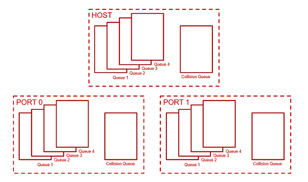
A memory region needs to be allocated for queues. There are 15 queues (Switch) or 12 queues (EMAC) in total. 4 queues for each port (including host) and 1 additional queue for each port to handle collision. This is covered later in Quality of Service and Queues. The firmware copies the packet data here after receiving them and this is where the driver writes the packet data meant for transmission using the firmware. So this acts as a place holder for packet data before it received or transmitted.
The size of this section can be configured using "Queue Buffer Size (KB)" option in SysConfig for ICSS-EMAC. A region with the configured size is created in MSRAM. This memory resides inside the SoC (but outside ICSS) and is faster than DDR.
This memory contains:
This is specific to the PRU subsystem although access is possible from Host albeit slowly. Data common to both PRUs is stored here. A lot of the memory is available for protocol or application specific usage, for more details refer to the memory map of the concerned firmware.
This memory contains host queue descriptors.
This is similar to Shared Data RAM though meant for use only by PRU0. Access from PRU1 is also possible, so the separation is only logical, not in hardware.
This memory contains:
Similar to PRU0 Data RAM, but for PRU1 and Port 1.
Quality of Service is very important for an ethernet switch as it allows high priority packets to be processed separately from regular packets. This provides reliability for real time traffic.
In EMAC this is done using queues which are mapped to 8 VLAN based priority levels. Each queue is a block of memory used to store the packet data. Queue sizes may vary and are configurable using ICSS_EMAC_FwDynamicMmap (which is a member of ICSS_EMAC_Params passed while calling ICSS_EMAC_open).
For example queue sizes used for EtherNet/IP Adapter application are given below. The sizes are denoted by blocks. Each block is 32 bytes in size. The transmit queues sizes are denoted separately (allows up to approximately 3KB queue size for each queue).
In total there are 15 queues, 4 receive queues for Host and 4 transmit queues for each of the two physical ports. In addition to these there is 1 collision queue each for Host and 2 ports which can hold one packet irrespective of packet size. The figure below is illustrative to remember this.
Data path refers to the control flow which is executed on the driver and firmware to send or receive a packet. A basic understanding of it goes a long way in explaining the software architecture. If a developer is only trying to use the Rx and Tx capabilities of EMAC or Switch, knowledge of this is sufficient to build an application.
Packets are received in the ICSS from where they are copied by the PRUs to ICSS-EMAC queue buffers memory region in MSRAM. The PRUs then assert an interrupt to tell the Host about the presence of a packet. PRU avoids corruption and does not write over the memory till the packet is copied by the Host.
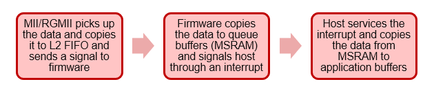
The flowchart shown above shows the sequence in very broad strokes. A detailed description is given below.
ICSS_EMAC_rxInterruptHandler which in turn posts a semaphore rxSemaphoreObject to signal RxTask task to empty the Rx queues.RxTask function goes through all the queues, extracts the port/queue number and provides it to an API which copies data from ICSS-EMAC queue buffers memory region (in MSRAM) to application buffers (destAddress mentioned in ICSS_EMAC_RxArgument). Please check the code for ICSS_EMAC_pollPkt function in ${SDK_INSTALL_PATH}/source/networking/icss_emac/source/icss_emac.c file for more details.In ICSS_EMAC_pollPkt, function ICSS_EMAC_rxPktInfo2 goes through each queue one at a time, extracts the port and queue number information for every packet and provides it to functions below. Based on the priority of the packet which is decided by the queue number (refer to Quality of Service and Queues), driver decides to either forward it to TCP/IP stack, done by rxNRTCallBack or give it to the rxRTCallBack function (if it is registered).
The threshold for this decision (ethPrioQueue in ICSS_EMAC_Attrs) can be configured using "RT/NRT Priority Separation Queue" option in SysConfig for ICSS-EMAC.
Anything lower than this configured value goes to the rxRTCallBack function. If a rxRTCallBack is not registered then the queue is just emptied to prevent queues from overflowing. This is done by the function ICSS_EMAC_rxPktGet which takes a single packet and copies it into dest_address provided as a parameter. This is not a dummy API but a basic Rx API which performs the task of copying data from ICSS-EMAC queue buffers to application buffers, even the TCP/IP stack API registered using rxNRTCallBack would internally call ICSS_EMAC_rxPktGet to fetch the packet data.
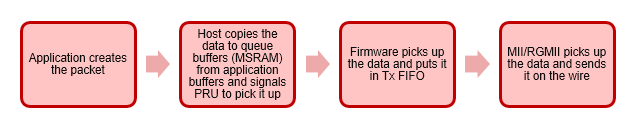
The Transmit path on host is simpler than the Rx path. ICSS_EMAC_txPacket API implements the Learning/FDB functionality and calls ICSS_EMAC_txPacketEnqueue which performs the actual task of copying data from application buffers (srcAddress configured in ICSS_EMAC_TxArgument) to ICSS-EMAC queue buffers and signals the PRU to transmit the data.
When ICSS_EMAC_txPacket is called with the parameter ICSS_EMAC_PORT_0 in portNumber field, it enables learning/FDB and calls the ICSS_EMAC_txPacketEnqueue with the correct port number. When it is called with parameter ICSS_EMAC_PORT_1 or ICSS_EMAC_PORT_1, it directly calls ICSS_EMAC_txPacketEnqueue.
Therefore ICSS_EMAC_txPacket should be called with with portNumber as
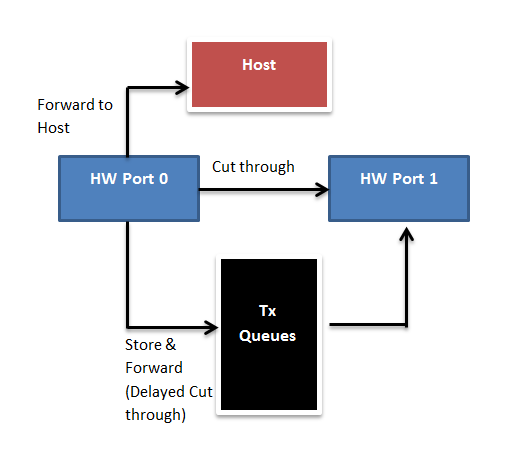
Forwarding Rules specify how packets are forwarded between ports and from the port to the host. There are three basic types of forwarding scenarios. The image below shows all modes when receiving on first port. HW Port represents the physical port. These modes are not exclusive to each other and multiple modes are also allowed.
Please note that EMAC can only forward to the Host, other modes only apply to switch.
| Packet Type | Forwarding Mode |
|---|---|
| Broadcast | Cut through and Forward to Host |
| Multicast | Cut through and Forward to Host Multicast frames like PTP/DLR are handled based on protocol |
| Unicast (not to Host) | Cut through |
| Unicast (to Host) | Forward to Host |
This section describes the OS entities used by ICSS-EMAC.
There are three interrupts registered for an ICSS-EMAC handle. For dual-emac use case, where two handles are created, one for each port, six interrupts will be registered. For switch use case, only three will be registered.
Three interrupts are:
These interrupts are routed from the ICSS Interrupt controller to the Host. It consists of interrupts asserted by the PRU as well as interrupts asserted by the peripherals (MDIO, ECAP etc) attached to the ICSS Interrupt controller. The Host Interrupt controller has 8 usable interrupts mapped to the ICSS interrupt controller. This mapping is programmable using PRUICSS_IntcInitData structure while passing ICSS_EMAC_Params for opening the ICSS-EMAC handle and it varies from example to example. Please refer PRUICSS Interrupt Controller page for more details.
Priorities for these tasks can be selected using the SysConfig for ICSS-EMAC. Task with ICSS_EMAC_osTxTaskFnc is created only if "TX Interrupt Enable" is checked in the SysConfig for ICSS-EMAC.
| Task Function Name | Description |
|---|---|
ICSS_EMAC_osLinkTaskFnc | Task to update the information regarding link status of port(s) |
ICSS_EMAC_osRxTaskFnc | Task to enable copying of Rx data from ICSS-EMAC queues to application buffers |
ICSS_EMAC_osTxTaskFnc | Task to call txCallBack when packet transmission is complete |
| Name | Description |
|---|---|
| linkSemaphoreObject | ICSS_EMAC_osLinkTaskFnc pends on it. It is posted in Link Interrupt ISR. |
| rxSemaphoreObject | ICSS_EMAC_osRxTaskFnc pends on it. It is posted in Rx Interrupt ISR. |
| txSemaphoreObject | ICSS_EMAC_osTxTaskFnc pends on it. It is posted in Tx Interrupt ISR. |
Interrupt pacing is the technique of pausing Rx interrupt to Host so that Host is not interrupted continuously when receiving high traffic.
When packets are sent to the Host at a very high rate (this happens more often with small frames), it is possible that ARM is interrupted frequently by the PRUs. This results in packets getting dropped as the host is unable to empty the queues in time because of context switching. Interrupt pacing is a scheme used to cope with this situation. In this scheme interrupts are disabled when the first Rx interrupt is received (The PRU still keeps receiving the frames and putting them on the queues), after a certain number of packets have been processed on the Host, the interrupts are enabled once more. Since interrupts on PRU have not been disabled any pending packets will assert the interrupt again, this ensures that no packets are missed. The scenario can also be explained in the form of a buffer fill and consumer/producer problem. With pacing enabled interrupt is not given until some threshold has been reached. This allows maximum use of buffer space and also allows Host to perform other tasks.
The advantage of pacing is that a greater throughput is achieved while disadvantage is that if any critical packets need to be serviced immediately, it is possible that some delay may occur. Other downside is that if a single frame comes then interrupt is not enabled until certain level is reached, causing a delay in response. So the pacing threshold must be chosen carefully.
Pacing can be enabled using "Interrupt Pacing Enable" option in SysConfig for ICSS-EMAC. If it is enabled, "Interrupt Pacing Mode" option should be used for selecting the mode. Only "Frame Count based" mode is supported right now, therefore "Interrupt Pacing Threshold Value" also should be configured in the SysConfig. This mode is based on number of frames. When first interrupt is received, interrupts are disabled until a certain threshold of frames are received. Threshold is programmable.Interrupts are disabled only on the Host. This does not require any firmware support.
Half Duplex support is enabled in the firmware for certain protocols like EtherNet/IP. Another requirement for Half Duplex support is enabling the Collision and Carrier Sense signals in MII.
ICSS-EMAC updates the flag (for half duplex) in Port Status offset in firmware. The flag "Half Duplex Enable" must be enabled in the SysConfig for this configuration.
Learning/FDB where FDB stands for "Forwarding Data Base" is a module that learns source MAC addresses of packets addressed to the Host and thus maintains a list of which devices reside on which port. While transmitting a packet when provided with the destination MAC address the module returns the port number on which the device resides. This avoids duplication of traffic on both ports. This module is applicable only in Switch mode, in EMAC mode this module is disabled since there is only one port.
Learning table is currently implemented as a Hash table. There is one table for each physical port. Each table has 256 buckets where a bucket has a size of 4. The bucket size and number of buckets are in turn dictated by the choice of Hashing algorithm. A detailed discussion on this topic is beyond the scope of this document, suffice to say that theoretically a hash table is capable of learning 256 * 4 = 1024 entries. The actual capacity may be lower owing to collisions.
A single bucket has :
A single table has :
Collisions are handled using ageing counters, one ageing counter is associated with each of the 4 entries inside a bucket. It tells the module which entries are old and which ones are new.
"Learning Enable" must be enabled in the SysConfig for using these features.
ICSS_EMAC_ioctl API should be called with ioctlCommand as ICSS_EMAC_IOCTL_LEARNING_CTRL for learning related configuration. Various commands available for learning are ICSS_EMAC_IOCTL_LEARNING_CTRL_COMMANDS, which should be passed as command in ICSS_EMAC_IoctlCmd used for ioctlParams parameter in ICSS_EMAC_ioctl API call.
Followings functions can be performed by using ICSS_EMAC_ioctl with appropriate parameters for learning:
Storm prevention or Storm Control is a feature that limits the number of broadcast and multicast packets going to the host and/or cutting through to the other port. Since broadcast and multicast packets are sent over all the ports of a switch they have the potential to create a storm which drowns all other traffic on the network. In this regard, this is a very important feature for the switch.
Storm prevention is implemented on the two PRUs as a credit based scheme. When the feature is enabled, every time a multicast or broadcast packet is received a counter referred to as storm prevention credits is decremented and the packet is sent to the host as well as cut through. If the counter value is 0 then the packet is dropped. The counter is stored on respective PRU DMEMs and is reset after a fixed period by the Host. The combination of this period and credit value decides the rate of acceptance/rejection.
The mechanism is shown below in the diagram.
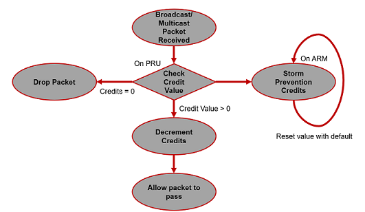
The storm prevention implementation is similar in both PRUs but implemented separately, so it is possible to turn it off selectively for each port. This functionality can be applied independently to broadcast, multicast and unicast packets.
ICSS_EMAC_ioctl API should be called with ioctlCommand as ICSS_EMAC_IOCTL_STORM_PREV_CTRL for storm prevention. Various commands available for storm prevention are ICSS_EMAC_IOCTL_STORM_PREV_CTRL_COMMANDS, which should be passed as command in ICSS_EMAC_IoctlCmd used for ioctlParams parameter in ICSS_EMAC_ioctl API call. Separate commands are available for broadcast packets, multicast packets, unicast packets and all packets.
Followings functions can be performed by using ICSS_EMAC_ioctl with appropriate parameters for storm prevention:
Statistics provide a great deal of information on what is going on with the switch. They are enabled by default and provide provide port specific statistics. They are also a great debugging tool and should be the first thing a developer should look at if they suspect any issue with Rx or Tx.
The statistics are divided into :
statisticsOffset configured in ICSS_EMAC_FwStaticMmap. ICSS_EMAC_PruStatistics is used for reading these statistics.Functionally the statistics are classified into :
ICSS_EMAC_ioctl API should be called with ioctlCommand as ICSS_EMAC_IOCTL_STATS_CTRL. Various commands available for statistics are ICSS_EMAC_IOCTL_STATISTICS_COMMANDS, which should be passed as command in ICSS_EMAC_IoctlCmd used for ioctlParams parameter in ICSS_EMAC_ioctl API call. These commands provide access to the PRU statistics only.
 1.8.20