Visual Localization Application
This application performs the ego vehicle localization that estimates an ego vehicle’s 6-DOF (Degree of Freedom) pose from calibrated camera images using a 3D sparse map created offline. The 3D sparse map consists of a set of key points with (X, Y, Z) positions and 64-dimensional descriptors. To localize the ego vehicle’s pose, key points are detected with descriptors from the input camera image and these key points are matched against the key points in the map. The ego vehicle’s pose is estimated using the Perspective-n-Point (PnP) approach.
Key-point descriptor plays critical role in the visual localization. In this demo, we use a deep neural network to learn hand computed feature descriptor like KAZE in a supervised manner. We refer such descriptor as DKAZE. The DAKZE network was used to create key features and their descriptors for the sparse 3D map and is also used to detect key feature points with descriptors for every input image in the localization process. For more details about the DKAZE network and the localization process, refer to Vision Apps User Guide.
For this demo, we provide the data set that has been created using Carla simulator. This data set includes an input rosbag file and the sparse 3D map crated offline, etc. The input rosbag file consists of a sequence of images in YUV422 (UYVY) format. Since the sparse 3D map should cover the area where the input image is being captured for localization. This demo does not work for live camera input with the provided sparse 3D map.

How to Run the Application in ROS1
Run the Visual Localization Demo
[J7] For setting up the ROS1 environment on J7 host, please follow Docker Setup for ROS 1. To launch ti_vl node with playing back a ROSBAG file, run the following inside the Docker container on J7 target:
roslaunch ti_vl bag_visloc.launch
[Visualization on Ubuntu PC] For setting up the ROS1 environment on remote PC, please follow Docker Setup for ROS 1.
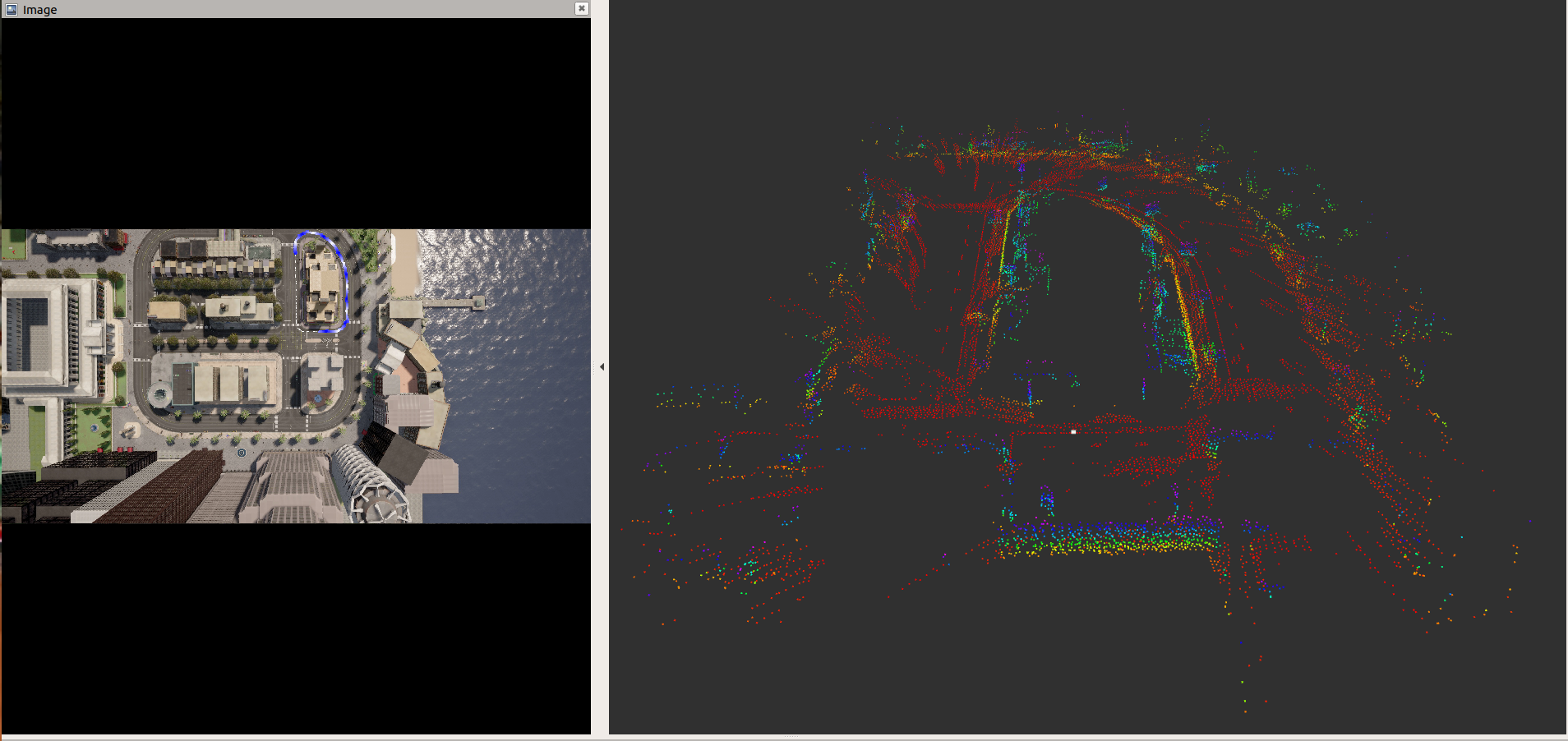
To display the top-down image with overlaid vehicle trajectory and pose in 3D space using RViz on PC, run:
roslaunch ti_viz_nodes rviz_visloc.launch
Launch File Parameters
| Parameter | Description | Value |
|---|---|---|
| rosparam file | Algorithm configuration parameters (see "ROSPARAM Parameters" section) | config/params.yaml |
| input_topic | Subscribe topic name for input camera image | camera/image_raw |
| out_image_topic | Publish topic name topic for top-down image with overlaid vehicle trajectory | vis_localize/out_image |
| out_pose_topic | Publish topic name topic for vehicle pose | vis_localize/pose |
| map_topic | Publish topic name for feature points in offline map | vis_localize/map |
| exportPerfStats | Flag for exporting the performance data to a file: 0 - disable, 1 - enable | 0, 1 |
| ## ROSPARM Parameters |
Basic input, DL model Parameters
| Parameter | Description | Value |
|---|---|---|
| input_format | Input image format, 0: YUV420, 1: YUV422 | 0, 1 |
| lut_file_path | LDC rectification table path | String |
| dl_model_path | Path to the feature detection DL model | String |
| width | Input image width | Integer |
| height | Input image height | Integer |
| out_width | Output semantic segmentation output (tensor) width | Integer |
| out_height | Output semantic segmentation output (tensor) height | Integer |
| pipeline_depth | OpenVX graph pipeline depth | 1 ~ 8 |
Visual Localization Parameters
The following shows the parameters necessary for visual localization. The default values are for the test data from a Carla simulator that we provide.
| Parameter | Description | Value |
|---|---|---|
| top_view_img_path | Path to top-down view image, on which vehicle trajectory is overlaid | String |
| input_voxel_info_path | Path to voxel info binary file | String |
| input_map_feat_pt_path | Path to binary file that has map key points' 3D position | String |
| input_map_feat_desc_path | Path to binary file that has map key points' descriptor | String |
| input_upsample_wt_path | Path to binary file that has upsampling coefficients for descriptor | String |
| input_upsample_bias_path | Path to binary file that has upsampling bias for descriptor | String |
| score_th | Score threshold for picking good key points | Integer |
| num_map_feat: | Number of key points in a map | Integer |
| max_frame_feat | Max number of key points for a frame | Integer |
| num_voxels | Number of voxels | Integer |
| filter_scale_pw2 | Scale of filter coefficients for input_upsample_wt_path | Integer |
| hi_res_desc_scale_pw2 | Scale of descriptors for input_map_feat_desc_path | Integer |
| pose_calc_skip_flag | Pose calculation skip flag (Should be 0) | 0, 1 |
Processing Blocks
Referring to Figure 1, below are the descriptions of the processing blocks implemented in this application:
The first step is to process input images. J7 LDC (Lens Distortion Correction) hardware accelerator (HWA) changes image format as well a removes lens distortion. The input format to the application is YUV422 (UYVY) format. It is converted to YUV420 (NV12) by the LDC.
Input images are resized to a smaller resolution, which is specified by
dl_widthanddl_heightinparams.yaml, for the DKAZE network. The MSC (Multi-Scaler) HWA resizes the images to a desired size.The pre-processing block converts YUV420 (NV12) to RGB, which is expected input format for the DKAZE network.
The DKAZE network is accelerated by C7x/MMA with DLR runtime, and outputs feature score tensor and feature descriptor tensor.
Two output tensors from the DAKZE network go to the pose calculation (PoseCalc) block, which runs on C6x. This block estimates the ego-vehicle’s pose.
The estimate pose goes to the pose visualization (PoseViz) block, which runs on C6x too. This block creates the top-down output image with overlaid vehicle’s trajectory. This output image is published along with the estimated pose.
Known Issues
The provided sparse 3D map is for the input bag file we provide. Both the input bag file and the sparse 3D map are created using CARLA simulator. Since the sparse 3D map should cover the area where the input image is being captured for localization. This demo does not work for live camera input with the provided sparse 3D map.