19.16.1. Scenario 1 – Hex Conversion Command File for a Single 8-Bit EPROM
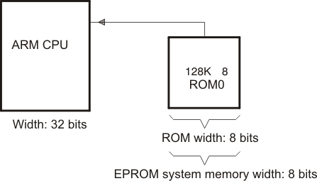
Scenario 1 shows how to build the hex conversion command file for converting an object file for the memory system shown in the following figure . In this system, there is one external 128K × 8-bit EPROM interfacing with a TMS470 target processor.
Figure: EPROM Memory System for Scenario 1
A object file consists of blocks of memory (sections) with assigned memory locations. Typically, all sections are not adjacent: there are holes between sections in the address space for which there is no data. Scenario 1 shows how you can use the hex conversion utility’s image mode to fill any holes before, between, or after sections with a fill value.
For this scenario, the application code resides in the program memory (ROM) on the TMS470 CPU, but the data tables used by this code reside in an off-chip EPROM.
The circuitry of the target board handles the access to the data; the native TMS470 address of 0x1000 accesses location 0x0 on the EPROM.
To satisfy the address requirements for the code, this scenario requires a linker command file that allocates sections and memory as follows:
The program/application code (represented in this scenario by the secA section shown in the following linker command file must be linked so that its address space resides in the program memory (ROM) on the TMS470 CPU.
To satisfy the condition that the data be loaded on the EPROM at address 0x0 but be referenced by the application code at address 0x1000, secB (the section that contains the data for this application) must be assigned a linker load address of 0x1000 so that all references to data in this section will be resolved with respect to the TMS470 CPU address. In the hex conversion utility command file, the paddr option must be used to burn the section of data at EPROM address 0x0. This value overrides the section load address given by the linker.
The following linker command file shows the MEMORY and SECTIONS directives that resolve the addresses needed in the stated specifications.
Example: Linker Command File and Link Map for Scenario 1
/****************************************************************************/
/* Scenario 1  Link Command                                                 */
/*                                                                          */
/*   Usage: armlnk <obj files...>    -o <out file> -m <map file> lnk32.cmd  */
/*          tiarmclang <src files...> -Wl,-o=out_file,-m=map_file lnk32.cmd */
/*                                                                          */
/*   Description: This file is a sample command file that can be used       */
/*                for linking programs built with the TMS470 C              */
/*                compiler.   Use it as a guideline; you may want to change */
/*                the allocation scheme according to the size of your       */
/*                program and the memory layout of your target system.      */
/*                                                                          */
/*   Notes: (1)   You must specify the directory in which rts32.lib is      */
/*                located.  Either add a "-i<directory>" line to this       */
/*                file, or use the system environment variable C_DIR to     */
/*                specify a search path for libraries.                      */
/*                                                                          */
/*          (2)   If the runtime-support library you are using is not       */
/*                named rts32.lib, be sure to use the correct name here.    */
/****************************************************************************/
-m example1.map

/* SPECIFY THE SYSTEM MEMORY MAP */
MEMORY
{
    I_MEM    : org = 0x00000000   len = 0x00000020  /* INTERRUPTS           */
    D_MEM    : org = 0x00000020   len = 0x00010000  /* DATA MEMORY    (RAM) */
    P_MEM    : org = 0x00010020   len = 0x00100000  /* PROGRAM MEMORY (ROM) */
}
/* SPECIFY THE SECTIONS ALLOCATION INTO MEMORY */
SECTIONS
{
    secA: load = P_MEM
    secB: load = 0x1000
}
You must create a hex conversion command file to generate a hex output with the correct addresses and format for the EPROM programmer.
In the memory system outlined in the figure above, only the application data is stored on the EPROM; the data resides in secB of the object file created by the linker. By default, the hex conversion utility converts all initialized sections that appear in the object file. To prevent the conversion of the application code in secA, a SECTIONS directive must be defined in the hex conversion command file to list explicitly the section(s) to be converted. In this case, secB must be listed explicitly as the section to be converted.
The EPROM programmer in this scenario has the following system requirements:
The EPROM programmer loads only a complete ROM image. A complete ROM image is one in which there is a contiguous address space (there are no holes in the addresses in the converted file), and each address in the range contains a known value. Creating a complete ROM image requires the use of the −image option and the ROMS directive.
Using the −image option causes the hex conversion utility to create an output file that has contiguous addresses over the specified memory range and forces the utility to fill address spaces that are not previously filled by raw data from sections defined in the input object file. By default, the value used to fill the unused portions of the memory range is 0.
Because the -image option operates over a known range of memory addresses, a ROMS directive is needed to specify the origin and length of the memory for the EPROM.
To burn the section of data at EPROM address 0x0, the paddr option must be used. This value overrides the section load address given by the linker.
In this scenario, the EPROM is 128K × 8 bits. Therefore, the memory addresses for the EPROM must range from 0x0 to 0x20000.
Because the EPROM memory width is eight bits, the memwidth value must be set to 8.
Because the physical width of the ROM device is eight bits, the romwidth value must be set to 8.
Intel format must be used.
Since memwidth and romwidth have the same value, only one output file is generated (the number of output files is determined by the ratio of memwidth to romwidth). The output file is named with the -o option.
The hex conversion command file for Scenario 1 is shown below. This command file uses the following options to select the requirements of the system:
Option |
Description |
|---|---|
-i |
Create Intel format |
-image |
Generate a memory image |
-map example1.mxp |
Generate example1.mxp as the map file of the conversion |
-o example1.hex |
Name example1.hex as the output file |
-memwidth 8 |
Set EPROM system memory width to 8 |
-romwidth 8 |
Set physical ROM width to 8 |
Example: Hex Conversion Command File for Scenario 1
/* Hex Conversion Command file for Scenario 1              */
a.out                  /* linked object file, input        */
-I                     /* Intel format                     */
-image
-map example1.mxp      /* Generate a map of the conversion */
-o example1.hex        /* Resulting hex output file        */
-memwidth 8            /* EPROM memory system width        */
-romwidth 8            /* Physical width of ROM            */

ROMS
{
    EPROM: origin = 0x0, length = 0x20000
}

SECTIONS
{
    secB: paddr = 0x0   /* Select only section, secB, for conversion */
}
The following example shows the contents of the resulting map file (example1.mxp).
Example: Contents of Hex Map File example1.mxp
**********************************************************
TMS470 Hex Converter               Version x.xx
**********************************************************

Mon Sep 18 15:57:00 1995

INPUT FILE NAME: <a.out>
OUTPUT FORMAT:   Intel

PHYSICAL MEMORY PARAMETERS
    Default data width:    8
    Default memory width:  8
    Default output width:  8

OUTPUT TRANSLATION MAP
---------------------------------------------------------
00000000..0001ffff  Page=0  ROM Width=8  Memory Width=8  "EPROM"
---------------------------------------------------------
    OUTPUT FILES: example1.hex [b0..b7]

    CONTENTS: 00000000..00000007  Data Width=1  secB
              00000007..0001ffff   FILL = 00000000
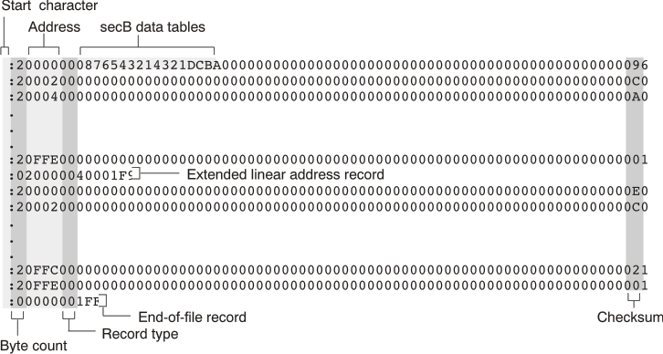
The following figure shows the contents of the resulting hex output file (example1.hex). The hex conversion utility places the data tables, secB, at address 0 and then fills the remainder of the address space with the default fill value of 0. For more information about the Intel MCS-86 object format, see Intel MCS-86 Object Format (--intel Option).
Figure: Contents of Hex Output File