19.11. Building a Table for an On-Chip Boot Loader
The Arm hex utility provides the ability to create a boot table for use with an on-chip boot loader. The supported boot formats are intended for use on C28x devices with Arm cores. The boot table is stored in memory or loaded from a device peripheral to initialize code or data.
See Bootstrap Loading for a general discussion of bootstrap loading.
19.11.1. Description of the Boot Table
The input for a boot loader is the boot table. The boot table contains records that instruct the on-chip loader to copy blocks of data contained in the table to specified destination addresses. The table can be stored in memory (such as EPROM) or read in through a device peripheral (such as a serial or communications port).
The hex conversion utility automatically builds the boot table for the boot loader. Using the utility, you specify the sections you want the boot loader to initialize and the table location. The hex conversion utility builds a complete image of the table according to the format specified and converts it into hexadecimal in the output files. Then, you can burn the table into ROM or load it by other means.
19.11.2. The Boot Table Format
The boot table format is simple. Typically, there is a header record containing a key value that indicates memory width, entry point, and values for control registers. Each subsequent block has a header containing the size and destination address of the block followed by data for the block. Multiple blocks can be entered. The table ends with a header containing size zero.
19.11.3. How to Build the Boot Table
The following list summarizes the hex conversion utility options available for the boot loader.
- --boot
Syntax: --boot
Converts all sections into boot table form (use instead of a SECTIONS directive).
- --bootorg
Syntax: --bootorg=value
Specifies the source address of the boot-loader table.
- --boot_align_sect
Syntax: --boot_align_sect
Causes boot table records to be aligned to the section alignment.
- --boot_block_size=size
Syntax: --boot_block_size=size
Set the desired block size for output from the hex conversion utility. The size may be specified as a hex or decimal value. The default size is 65535 (0xFFFF). For ARM targets, the boot block size refers to 8-bit bytes.
- --entrypoint
Syntax: --entrypoint=value
Specifies the entry point at which to begin execution after boot loading. The value can be an address or a global symbol.
- --gpio8
Syntax: --gpio8
Specifies the source of the boot-loader table as the GP I/O port, 8-bit mode.
- --gpio16
Syntax: --gpio16
Specifies the source of the boot-loader table as the GP I/O port, 16-bit mode.
- --lospcp
Syntax: --lospcp=value
Specifies the initial value for the LOSPCP register. The value is used only for the spi8 boot table format and is ignored for all other formats. A value greater than 0x7F is truncated to 0x7F.
- --spi8
Syntax: --spi8
Specifies the source of the boot-loader table as the SPI-A port, 8-bit mode.
- --spibrr
Syntax: --spibrr=value
Specifies the initial value for the SPIBRR register. The value is used only for the spi8 boot table format and is ignored for all other formats. A value greater than 0x7F is truncated to 0x7F.
19.11.3.1. Building the Boot Table
To build the boot table, follow these steps:
Step 1: Link the file. Each block of the boot table data corresponds to an initialized section in the object file. Uninitialized sections are not converted by the hex conversion utility (see The SECTIONS Directive).
When you select a section for placement in a boot-loader table, the hex conversion utility places the section’s load address in the destination address field for the block in the boot table. The section content is then treated as raw data for that block. The hex conversion utility does not use the section run address. When linking, you need not worry about the ROM address or the construction of the boot table; the hex conversion utility handles this.
Step 2: Identify the bootable sections. You can use the --boot option to tell the hex conversion utility to configure all sections for boot loading. Or, you can use a SECTIONS directive to select specific sections to be configured (see The SECTIONS Directive). If you use a SECTIONS directive, the --boot option is ignored.
Step 3: Set the boot table format. Specify the --gpio8, --gpio16, or --spi8 options to set the source format of the boot table. You do not need to specify the memwidth and romwidth as the utility will set these formats automatically. If --memwidth and --romwidth are used after a format option, they override the default for the format.
Step 4: Set the ROM address of the boot table. Use the --bootorg option to set the source address of the complete table.
Step 5: Set boot-loader-specific options. Set entry point and control register values as needed.
Step 6: Describe your system memory configuration. See Understanding Memory Widths and The ROMS Directive.
19.11.3.2. Leaving Room for the Boot Table
The complete boot table is similar to a single section containing all of the header records and data for the boot loader. The address of this section is the boot table origin. As part of the normal conversion process, the hex conversion utility converts the boot table to hexadecimal format and maps it into the output files like any other section.
Be sure to leave room in your system memory for the boot table, especially when you are using the ROMS directive. The boot table cannot overlap other nonboot sections or unconfigured memory. Usually, this is not a problem; typically, a portion of memory in your system is reserved for the boot table. Simply configure this memory as one or more ranges in the ROMS directive, and use the --bootorg option to specify the starting address.
19.11.4. Booting From a Device Peripheral
You can choose the port to boot from by using the --gpio8, --gpio16, or --spi8 boot table format option.
The initial value for the LOSPCP register can be specified with the --lospcp option. The initial value for the SPIBRR register can be specified with the --spibrr option. Only the --spi8 format uses these control register values in the boot table.
If the register values are not specified for the --spi8 format, the hex conversion utility uses the default values 0x02 for LOSPCP and 0x7F for SPIBRR. When the boot table format options are specified and the ROMS directive is not specified, the ASCII format hex utility output does not produce the address record.
19.11.5. Setting the Entry Point for the Boot Table
After completing the boot load process, execution starts at the default entry point specified by the linker and contained in the object file. By using the --entrypoint option with the hex conversion utility, you can set the entry point to a different address.
For example, if you want your program to start running at address 0x0123 after loading, specify --entrypoint=0x0123 on the command line or in a command file. You can determine the --entrypoint address by looking at the map file that the linker generates.
Note
Valid Entry Points The value can be a constant, or it can be a symbol that is externally defined (for example, with a .global) in the assembly source.
19.11.6. Using the Arm Boot Loader
This subsection explains how to use the hex conversion utility with the boot loader for C28x devices with Arm cores. The boot loader accepts the formats listed in the following table.
Boot Table Source Formats
Format |
Option |
|---|---|
Parallel boot GP I/O 8 bit |
--gpio8 |
Parallel boot GP I/O 16 bit |
--gpio16 |
8-bit SPI boot |
--spi8 |
The Arm on C28x devices with Arm cores can boot through the SPI-A 8-bit, GP I/O 8-bit, or GP I/I 16-bit interface. The format of the boot table is shown in the following table.
Boot Table Format
Description |
Bytes |
Content |
|---|---|---|
Boot table header |
1-2 |
Key value (0x10AA or 0x08AA) |
3-18 |
Register initialization value or reserved for future use |
|
19-22 |
Entry point |
|
Block header |
23-24 |
Block size in number of bytes (nl) |
25-28 |
Destination address of the block |
|
Block data |
29-30 |
Raw data for the block (nl bytes) |
Block header |
31 + nl |
Block size in number of bytes |
. |
Destination address of the block |
|
Block data |
. |
Raw data for the block |
Additional block headers and data, as required |
… |
Content as appropriate |
Block header with size 0 |
0x0000; indicates the end of the boot table. |
The Arm on C28x devices with Arm cores can boot through either the serial 8-bit or parallel interface with either 8- or 16-bit data. The format is the same for any combination: the boot table consists of a field containing the destination address, a field containing the length, and a block containing the data. You can boot only one section. If you are booting from an 8-bit channel, 8-bit bytes are stored in the table with MSBs first; the hex conversion utility automatically builds the table in the correct format. Use the following options to specify the boot table source:
To boot from a SPI-A port, specify --spi8 when invoking the utility. Do not specify --memwidth or --romwidth. Use --lospcp to set the initial value for the LOSPCP register and --spibrr to set the initial value for the SPIBRR register. If the register values are not specified for the --spi8 format, the hex conversion utility uses the default value 0x02 for LOSPCP and 0x7F for SPIBRR.
To load from a general-purpose parallel I/O port, invoke the utility with --gpio8 or --gpio16. Do not specify --memwidth or --romwidth.
The command file in the following example allows you to boot the .text and .cinit sections of test.out from a 16-bit-wide EPROM at location 0x3FFC00. The map file test.map is also generated.
Example: Sample Command File for Booting From 8-Bit SPI Boot
/*---------------------------------------------------------------------------*/
/* Hex converter command file.                                               */
/*---------------------------------------------------------------------------*/
test.out                 /* Input file */
--ascii                  /* Select ASCII format */
--map=test.map           /* Specify the map file */
--outfile=test_spi8.hex  /* Hex utility out file */
--boot                   /* Consider all the input sections as boot sections */
--spi8                   /* Specify the SPI 8-bit boot format */
--lospcp=0x3F            /* Set the initial value for the LOSPCP as 0x3F */
                         /* The -spibrr option is not specified to show that */
                         /* the hex utility uses the default value (0x7F) */
--entrypoint=0x3F0000    /* Set the entry point */
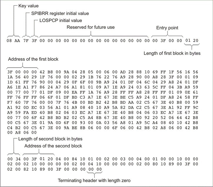
The command file in the example above generates the out file in the following figure. The control register values are coded in the boot table header and that header has the address that is specified with the --entrypoint option.
Figure: Sample Hex Converter Out File for Booting From 8-Bit SPI Boot
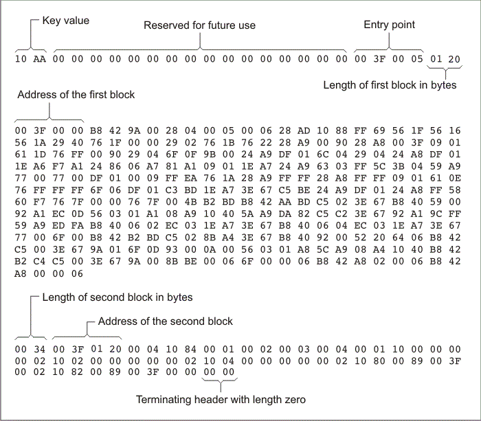
The command file in the following example allows you to boot the .text and .cinit sections of test.out from the 16-bit parallel GP I/O port. The map file test.map is also generated.
Example: Sample Command File for Arm 16-Bit Parallel Boot GP I/O
/*---------------------------------------------------------------------*/
/* Hex converter command file.                                         */
/*---------------------------------------------------------------------*/
test.out                   /* Input file */
--ascii                    /* Select ASCII format */
--map=test.map             /* Specify the map file */
--outfile=test_gpio16.hex  /* Hex utility out file */
--gpio16                   /* Specify the 16-bit GP I/O boot format */

SECTIONS
{
    .text: paddr=BOOT
    .cinit: paddr=BOOT
}
The command file above generates the out file shown below:
Figure: Sample Hex Converter Out File for Arm 16-Bit Parallel Boot GP I/O