PMBUS Module
The PMBus peripheral module supports both master and slave features and is compliant to the PMBus protocol v1.0. It supports the following transactions: * Quick Command * Send Byte * Write Byte * Write Word * Block Write * Receive Byte * Alert Response * Read Byte * Read Word * Block Read * Block Write/ Read/ Process Call * Group Command * Extended Read/Write Byte/Word
The PMBus Communications Stack is available as a separate library with support for the slave mode of operation and a state machine to handle the transactions mentioned above.
The PMBus module can also be placed into I2C mode, and the existing functions in driverlib can be used to communicate on an I2C bus. The I2C mode is compliant to the Philips specification with one exception – in the event of an arbitration lost the module does not automatically switch from master to slave mode. The user must poll the ARB_LOST bit in the status register and then place the module in slave mode before it is able to receive any data from the winning master.
The code for this module is contained in driverlib/pmbus.c, with driverlib/pmbus.h containing the API declarations for use by applications.
-
group
pmbus_api Defines
-
PMBUS_INCLUDE_CRC8_TABLE0x1U¶ Specifies whether to include the CRC8 table in the library build
-
PMBUS_MASTER_ENABLE_PRC_CALL0x00100000U¶ Enable Process call message.
-
PMBUS_MASTER_ENABLE_GRP_CMD0x00080000U¶ Enable Group command message.
-
PMBUS_MASTER_ENABLE_PEC0x00040000U¶ Enable PEC byte.
-
PMBUS_MASTER_ENABLE_EXT_CMD0x00020000U¶ Enable Extended command.
-
PMBUS_MASTER_ENABLE_CMD0x00010000U¶ Enable Command word.
-
PMBUS_MASTER_ENABLE_READ0x00000001U¶ Enable read.
-
PMBUS_INT_BUS_FREE0x00000001U¶ Bus Free Interrupt.
-
PMBUS_INT_CLK_LOW_TIMEOUT0x00000002U¶ Clock Low Time-out Interrupt.
-
PMBUS_INT_DATA_READY0x00000004U¶ Data Ready Interrupt.
-
PMBUS_INT_DATA_REQUEST0x00000008U¶ Data Request Interrupt.
-
PMBUS_INT_SLAVE_ADDR_READY0x00000010U¶ Slave Address Ready Interrupt.
-
PMBUS_INT_EOM0x00000020U¶ End of Message Interrupt.
-
PMBUS_INT_ALERT0x00000040U¶ Alert Detection Interrupt.
-
PMBUS_INT_CONTROL0x00000080U¶ Control Detection Interrupt.
-
PMBUS_INT_LOST_ARB0x00000100U¶ Lost Arbitration Interrupt.
-
PMBUS_INT_CLK_HIGH_DETECT0x00000200U¶ Clock High Detection Interrupt.
-
PMBUS_INT_ALL0x000003FFU¶ all PMBus interrupts
-
PMBUS_INTSRC_BUS_FREE0x00002000U¶ Bus Free Interrupt.
-
PMBUS_INTSRC_CLK_LOW_TIMEOUT0x00000100U¶ Clock Low Time-out Interrupt.
-
PMBUS_INTSRC_DATA_READY0x00000008U¶ Data Ready Interrupt.
-
PMBUS_INTSRC_DATA_REQUEST0x00000010U¶ Data Request Interrupt.
-
PMBUS_INTSRC_SLAVE_ADDR_READY0x00000400U¶ Slave Address Ready Interrupt.
-
PMBUS_INTSRC_EOM0x00000020U¶ End of Message Interrupt.
-
PMBUS_INTSRC_ALERT0x00010000U¶ Alert Detection Interrupt.
-
PMBUS_INTSRC_CONTROL0x00020000U¶ Control Detection Interrupt.
-
PMBUS_INTSRC_LOST_ARB0x00004000U¶ Lost Arbitration Interrupt.
-
PMBUS_INTSRC_CLK_HIGH_DETECT0x00000200U¶ Clock High Detection Interrupt.
-
PMBUS_SLAVE_ENABLE_MANUAL_ACK0x00000080U¶ Enable manual slave ack modes.
-
PMBUS_SLAVE_ENABLE_PEC_PROCESSING0x00008000U¶ Enable PEC byte processing.
-
PMBUS_SLAVE_TRANSMIT_PEC0x00080000U¶ Transmit PEC at end of transaction.
-
PMBUS_SLAVE_ENABLE_MANUAL_CMD_ACK0x00100000U¶ Data Request flag generated after receipt of command code, firmware required to issue ACK to continue message
-
PMBUS_SLAVE_DISABLE_ADDRESS_MASK0x0000007FU¶ any bits cleared in slave address mask make that bit a don’t care
-
PMBUS_SLAVE_AUTO_ACK_1_BYTES0x00000000U¶ Slave will auto acknowledge every received byte.
-
PMBUS_SLAVE_AUTO_ACK_2_BYTES0x00200000U¶ Slave will auto acknowledge every 2 received bytes.
-
PMBUS_SLAVE_AUTO_ACK_3_BYTES0x00400000U¶ Slave will auto acknowledge every 3 received bytes.
-
PMBUS_SLAVE_AUTO_ACK_4_BYTES0x00600000U¶ Slave will auto acknowledge every 4 received bytes.
-
PMBUS_RESET0x00000001U¶ Reset control state machines.
-
PMBUS_ENABLE_SLAVE_ALERT0x00000002U¶ Enable Slave Alert.
-
PMBUS_SET_BUS_LO_INT_FALLING_EDGE0x00000004U¶ Set Clock Low Time-out Interrupt generation on falling edge.
-
PMBUS_SET_CNTL_INT_RISING_EDGE0x00000020U¶ Set Control Interrupt to be generated on rising edge.
-
PMBUS_ENABLE_IBIAS_A_EN0x00040000U¶ Enable PMBus Current Source A Control.
-
PMBUS_ENABLE_IBIAS_B_EN0x00080000U¶ Enable PMBus Current Source B Control.
-
PMBUS_DISABLE_CLK_LOW_TIMEOUT0x00100000U¶ Disable Clock Low Time-out.
-
PMBUS_ENABLE_SLAVE_MODE0x00200000U¶ Enable PMBus Slave Enable.
-
PMBUS_ENABLE_MASTER_MODE0x00400000U¶ Enable PMBus Master Enable.
-
PMBUS_CMD_PAGE(0x00U)¶ PMBus Command PAGE.
-
PMBUS_CMD_OPERATION(0x01U)¶ PMBus Command OPERATION.
-
PMBUS_CMD_ON_OFF_CONFIG(0x02U)¶ PMBus Command ON_OFF_CONFIG.
-
PMBUS_CMD_CLEAR_FAULTS(0x03U)¶ PMBus Command CLEAR_FAULTS.
-
PMBUS_CMD_PHASE(0x04U)¶ PMBus Command PHASE.
-
PMBUS_CMD_PAGE_PLUS_WRITE(0x05U)¶ PMBus Command PAGE_PLUS_WRITE.
-
PMBUS_CMD_PAGE_PLUS_READ(0x06U)¶ PMBus Command PAGE_PLUS_READ.
-
PMBUS_CMD_WRITE_PROTECT(0x10U)¶ PMBus Command WRITE_PROTECT.
-
PMBUS_CMD_STORE_DEFAULT_ALL(0x11U)¶ PMBus Command STORE_DEFAULT_ALL.
-
PMBUS_CMD_RESTORE_DEFAULT_ALL(0x12U)¶ PMBus Command RESTORE_DEFAULT_ALL.
-
PMBUS_CMD_STORE_DEFAULT_CODE(0x13U)¶ PMBus Command STORE_DEFAULT_CODE.
-
PMBUS_CMD_RESTORE_DEFAULT_CODE(0x14U)¶ PMBus Command RESTORE_DEFAULT_CODE.
-
PMBUS_CMD_STORE_USER_ALL(0x15U)¶ PMBus Command STORE_USER_ALL.
-
PMBUS_CMD_RESTORE_USER_ALL(0x16U)¶ PMBus Command RESTORE_USER_ALL.
-
PMBUS_CMD_STORE_USER_CODE(0x17U)¶ PMBus Command STORE_USER_CODE.
-
PMBUS_CMD_RESTORE_USER_CODE(0x18U)¶ PMBus Command RESTORE_USER_CODE.
-
PMBUS_CMD_CAPABILITY(0x19U)¶ PMBus Command CAPABILITY.
-
PMBUS_CMD_QUERY(0x1AU)¶ PMBus Command QUERY.
-
PMBUS_CMD_SMBALERT_MASK(0x1BU)¶ PMBus Command SMBALERT_MASK.
-
PMBUS_CMD_VOUT_MODE(0x20U)¶ PMBus Command VOUT_MODE.
-
PMBUS_CMD_VOUT_COMMAND(0x21U)¶ PMBus Command VOUT_COMMAND.
-
PMBUS_CMD_VOUT_TRIM(0x22U)¶ PMBus Command VOUT_TRIM.
-
PMBUS_CMD_VOUT_CAL_OFFSET(0x23U)¶ PMBus Command VOUT_CAL_OFFSET.
-
PMBUS_CMD_VOUT_MAX(0x24U)¶ PMBus Command VOUT_MAX.
-
PMBUS_CMD_VOUT_MARGIN_HIGH(0x25U)¶ PMBus Command VOUT_MARGIN_HIGH.
-
PMBUS_CMD_VOUT_MARGIN_LOW(0x26U)¶ PMBus Command VOUT_MARGIN_LOW.
-
PMBUS_CMD_VOUT_TRANSITION_RATE(0x27U)¶ PMBus Command VOUT_TRANSITION_RATE.
-
PMBUS_CMD_VOUT_DROOP(0x28U)¶ PMBus Command VOUT_DROOP.
-
PMBUS_CMD_VOUT_SCALE_LOOP(0x29U)¶ PMBus Command VOUT_SCALE_LOOP.
-
PMBUS_CMD_VOUT_SCALE_MONITOR(0x2AU)¶ PMBus Command VOUT_SCALE_MONITOR.
-
PMBUS_CMD_COEFFICIENTS(0x30U)¶ PMBus Command COEFFICIENTS.
-
PMBUS_CMD_POUT_MAX(0x31U)¶ PMBus Command POUT_MAX.
-
PMBUS_CMD_MAX_DUTY(0x32U)¶ PMBus Command MAX_DUTY.
-
PMBUS_CMD_FREQUENCY_SWITCH(0x33U)¶ PMBus Command FREQUENCY_SWITCH.
-
PMBUS_CMD_VIN_ON(0x35U)¶ PMBus Command VIN_ON.
-
PMBUS_CMD_VIN_OFF(0x36U)¶ PMBus Command VIN_OFF.
-
PMBUS_CMD_INTERLEAVE(0x37U)¶ PMBus Command INTERLEAVE.
-
PMBUS_CMD_IOUT_CAL_GAIN(0x38U)¶ PMBus Command IOUT_CAL_GAIN.
-
PMBUS_CMD_IOUT_CAL_OFFSET(0x39U)¶ PMBus Command IOUT_CAL_OFFSET.
-
PMBUS_CMD_FAN_CONFIG_1_2(0x3AU)¶ PMBus Command FAN_CONFIG_1_2.
-
PMBUS_CMD_FAN_COMMAND_1(0x3BU)¶ PMBus Command FAN_COMMAND_1.
-
PMBUS_CMD_FAN_COMMAND_2(0x3CU)¶ PMBus Command FAN_COMMAND_2.
-
PMBUS_CMD_FAN_CONFIG_3_4(0x3DU)¶ PMBus Command FAN_CONFIG_3_4.
-
PMBUS_CMD_FAN_COMMAND_3(0x3EU)¶ PMBus Command FAN_COMMAND_3.
-
PMBUS_CMD_FAN_COMMAND_4(0x3FU)¶ PMBus Command FAN_COMMAND_4.
-
PMBUS_CMD_VOUT_OV_FAULT_LIMIT(0x40U)¶ PMBus Command VOUT_OV_FAULT_LIMIT.
-
PMBUS_CMD_VOUT_OV_FAULT_RESPONSE(0x41U)¶ PMBus Command VOUT_OV_FAULT_RESPONSE.
-
PMBUS_CMD_VOUT_OV_WARN_LIMIT(0x42U)¶ PMBus Command VOUT_OV_WARN_LIMIT.
-
PMBUS_CMD_VOUT_UV_WARN_LIMIT(0x43U)¶ PMBus Command VOUT_UV_WARN_LIMIT.
-
PMBUS_CMD_VOUT_UV_FAULT_LIMIT(0x44U)¶ PMBus Command VOUT_UV_FAULT_LIMIT.
-
PMBUS_CMD_VOUT_UV_FAULT_RESPONSE(0x45U)¶ PMBus Command VOUT_UV_FAULT_RESPONSE.
-
PMBUS_CMD_IOUT_OC_FAULT_LIMIT(0x46U)¶ PMBus Command IOUT_OC_FAULT_LIMIT.
-
PMBUS_CMD_IOUT_OC_FAULT_RESPONSE(0x47U)¶ PMBus Command IOUT_OC_FAULT_RESPONSE.
-
PMBUS_CMD_IOUT_OC_LV_FAULT_LIMIT(0x48U)¶ PMBus Command IOUT_OC_LV_FAULT_LIMIT.
-
PMBUS_CMD_IOUT_OC_LV_FAULT_RESPONSE(0x49U)¶ PMBus Command IOUT_OC_LV_FAULT_RESPONSE.
-
PMBUS_CMD_IOUT_OC_WARN_LIMIT(0x4AU)¶ PMBus Command IOUT_OC_WARN_LIMIT.
-
PMBUS_CMD_IOUT_UC_FAULT_LIMIT(0x4BU)¶ PMBus Command IOUT_UC_FAULT_LIMIT.
-
PMBUS_CMD_IOUT_UC_FAULT_RESPONSE(0x4CU)¶ PMBus Command IOUT_UC_FAULT_RESPONSE.
-
PMBUS_CMD_OT_FAULT_LIMIT(0x4FU)¶ PMBus Command OT_FAULT_LIMIT.
-
PMBUS_CMD_OT_FAULT_RESPONSE(0x50U)¶ PMBus Command OT_FAULT_RESPONSE.
-
PMBUS_CMD_OT_WARN_LIMIT(0x51U)¶ PMBus Command OT_WARN_LIMIT.
-
PMBUS_CMD_UT_WARN_LIMIT(0x52U)¶ PMBus Command UT_WARN_LIMIT.
-
PMBUS_CMD_UT_FAULT_LIMIT(0x53U)¶ PMBus Command UT_FAULT_LIMIT.
-
PMBUS_CMD_UT_FAULT_RESPONSE(0x54U)¶ PMBus Command UT_FAULT_RESPONSE.
-
PMBUS_CMD_VIN_OV_FAULT_LIMIT(0x55U)¶ PMBus Command VIN_OV_FAULT_LIMIT.
-
PMBUS_CMD_VIN_OV_FAULT_RESPONSE(0x56U)¶ PMBus Command VIN_OV_FAULT_RESPONSE.
-
PMBUS_CMD_VIN_OV_WARN_LIMIT(0x57U)¶ PMBus Command VIN_OV_WARN_LIMIT.
-
PMBUS_CMD_VIN_UV_WARN_LIMIT(0x58U)¶ PMBus Command VIN_UV_WARN_LIMIT.
-
PMBUS_CMD_VIN_UV_FAULT_LIMIT(0x59U)¶ PMBus Command VIN_UV_FAULT_LIMIT.
-
PMBUS_CMD_VIN_UV_FAULT_RESPONSE(0x5AU)¶ PMBus Command VIN_UV_FAULT_RESPONSE.
-
PMBUS_CMD_IIN_OC_FAULT_LIMIT(0x5BU)¶ PMBus Command IIN_OC_FAULT_LIMIT (For CBC current limit)
-
PMBUS_CMD_IIN_OC_FAULT_RESPONSE(0x5CU)¶ PMBus Command IIN_OC_FAULT_RESPONSE.
-
PMBUS_CMD_IIN_OC_WARN_LIMIT(0x5DU)¶ PMBus Command IIN_OC_WARN_LIMIT.
-
PMBUS_CMD_POWER_GOOD_ON(0x5EU)¶ PMBus Command POWER_GOOD_ON.
-
PMBUS_CMD_POWER_GOOD_OFF(0x5FU)¶ PMBus Command POWER_GOOD_OFF.
-
PMBUS_CMD_TON_DELAY(0x60U)¶ PMBus Command TON_DELAY.
-
PMBUS_CMD_TON_RISE(0x61U)¶ PMBus Command TON_RISE.
-
PMBUS_CMD_TON_MAX_FAULT_LIMIT(0x62U)¶ PMBus Command TON_MAX_FAULT_LIMIT.
-
PMBUS_CMD_TON_MAX_FAULT_RESPONSE(0x63U)¶ PMBus Command TON_MAX_FAULT_RESPONSE.
-
PMBUS_CMD_TOFF_DELAY(0x64U)¶ PMBus Command TOFF_DELAY.
-
PMBUS_CMD_TOFF_FALL(0x65U)¶ PMBus Command TOFF_FALL.
-
PMBUS_CMD_TOFF_MAX_WARN_LIMIT(0x66U)¶ PMBus Command TOFF_MAX_WARN_LIMIT.
-
PMBUS_CMD_POUT_OP_FAULT_LIMIT(0x68U)¶ PMBus Command POUT_OP_FAULT_LIMIT.
-
PMBUS_CMD_POUT_OP_FAULT_RESPONSE(0x69U)¶ PMBus Command POUT_OP_FAULT_RESPONSE.
-
PMBUS_CMD_POUT_OP_WARN_LIMIT(0x6AU)¶ PMBus Command POUT_OP_WARN_LIMIT.
-
PMBUS_CMD_PIN_OP_WARN_LIMIT(0x6BU)¶ PMBus Command PIN_OP_WARN_LIMIT.
-
PMBUS_CMD_STATUS_BYTE(0x78U)¶ PMBus Command STATUS_BYTE.
-
PMBUS_CMD_STATUS_WORD(0x79U)¶ PMBus Command STATUS_WORD.
-
PMBUS_CMD_STATUS_VOUT(0x7AU)¶ PMBus Command STATUS_VOUT.
-
PMBUS_CMD_STATUS_IOUT(0x7BU)¶ PMBus Command STATUS_IOUT.
-
PMBUS_CMD_STATUS_INPUT(0x7CU)¶ PMBus Command STATUS_INPUT.
-
PMBUS_CMD_STATUS_TEMPERATURE(0x7DU)¶ PMBus Command STATUS_TEMPERATURE.
-
PMBUS_CMD_STATUS_CML(0x7EU)¶ PMBus Command STATUS_CML.
-
PMBUS_CMD_STATUS_OTHER(0x7FU)¶ PMBus Command STATUS_OTHER.
-
PMBUS_CMD_STATUS_MFR_SPECIFIC(0x80U)¶ PMBus Command STATUS_MFR_SPECIFIC.
-
PMBUS_CMD_STATUS_FANS_1_2(0x81U)¶ PMBus Command STATUS_FANS_1_2.
-
PMBUS_CMD_STATUS_FANS_3_4(0x82U)¶ PMBus Command STATUS_FANS_3_4.
-
PMBUS_CMD_READ_EIN(0x86U)¶ PMBus Command READ_EIN.
-
PMBUS_CMD_READ_EOUT(0x87U)¶ PMBus Command READ_EOUT.
-
PMBUS_CMD_READ_VIN(0x88U)¶ PMBus Command READ_VIN.
-
PMBUS_CMD_READ_IIN(0x89U)¶ PMBus Command READ_IIN.
-
PMBUS_CMD_READ_VCAP(0x8AU)¶ PMBus Command READ_VCAP.
-
PMBUS_CMD_READ_VOUT(0x8BU)¶ PMBus Command READ_VOUT.
-
PMBUS_CMD_READ_IOUT(0x8CU)¶ PMBus Command READ_IOUT.
-
PMBUS_CMD_READ_TEMPERATURE_1(0x8DU)¶ PMBus Command READ_TEMPERATURE_1.
-
PMBUS_CMD_READ_TEMPERATURE_2(0x8EU)¶ PMBus Command READ_TEMPERATURE_2.
-
PMBUS_CMD_READ_TEMPERATURE_3(0x8FU)¶ PMBus Command READ_TEMPERATURE_3.
-
PMBUS_CMD_READ_FAN_SPEED_1(0x90U)¶ PMBus Command READ_FAN_SPEED_1.
-
PMBUS_CMD_READ_FAN_SPEED_2(0x91U)¶ PMBus Command READ_FAN_SPEED_2.
-
PMBUS_CMD_READ_FAN_SPEED_3(0x92U)¶ PMBus Command READ_FAN_SPEED_3.
-
PMBUS_CMD_READ_FAN_SPEED_4(0x93U)¶ PMBus Command READ_FAN_SPEED_4.
-
PMBUS_CMD_READ_DUTY_CYCLE(0x94U)¶ PMBus Command READ_DUTY_CYCLE.
-
PMBUS_CMD_READ_FREQUENCY(0x95U)¶ PMBus Command READ_FREQUENCY.
-
PMBUS_CMD_READ_POUT(0x96U)¶ PMBus Command READ_POUT.
-
PMBUS_CMD_READ_PIN(0x97U)¶ PMBus Command READ_PIN.
-
PMBUS_CMD_PMBUS_REVISION(0x98U)¶ PMBus Command PMBUS_REVISION.
-
PMBUS_CMD_MFR_ID(0x99U)¶ PMBus Command MFR_ID.
-
PMBUS_CMD_MFR_MODEL(0x9AU)¶ PMBus Command MFR_MODEL.
-
PMBUS_CMD_MFR_REVISION(0x9BU)¶ PMBus Command MFR_REVISION.
-
PMBUS_CMD_MFR_LOCATION(0x9CU)¶ PMBus Command MFR_LOCATION.
-
PMBUS_CMD_MFR_DATE(0x9DU)¶ PMBus Command MFR_DATE.
-
PMBUS_CMD_MFR_SERIAL(0x9EU)¶ PMBus Command MFR_SERIAL.
-
PMBUS_CMDAPP_PROFILE_SUPPORT (0x9FU)¶ PMBus Command APP_PROFILE_SUPPORT.
-
PMBUS_CMD_MFR_VIN_MIN(0xA0U)¶ PMBus Command MFR_VIN_MIN.
-
PMBUS_CMD_MFR_VIN_MAX(0xA1U)¶ PMBus Command MFR_VIN_MAX.
-
PMBUS_CMD_MFR_IIN_MAX(0xA2U)¶ PMBus Command MFR_IIN_MAX.
-
PMBUS_CMD_MFR_PIN_MAX(0xA3U)¶ PMBus Command MFR_PIN_MAX.
-
PMBUS_CMD_MFR_VOUT_MIN(0xA4U)¶ PMBus Command MFR_VOUT_MIN.
-
PMBUS_CMD_MFR_VOUT_MAX(0xA5U)¶ PMBus Command MFR_VOUT_MAX.
-
PMBUS_CMD_MFR_IOUT_MAX(0xA6U)¶ PMBus Command MFR_IOUT_MAX.
-
PMBUS_CMD_MFR_POUT_MAX(0xA7U)¶ PMBus Command MFR_POUT_MAX.
-
PMBUS_CMD_MFR_TAMBIENT_MAX(0xA8U)¶ PMBus Command MFR_TAMBIENT_MAX.
-
PMBUS_CMD_MFR_TAMBIENT_MIN(0xA9U)¶ PMBus Command MFR_TAMBIENT_MIN.
-
PMBUS_CMD_MFR_EFFICIENCY_LL(0xAAU)¶ PMBus Command MFR_EFFICIENCY_LL.
-
PMBUS_CMD_MFR_EFFICIENCY_HL(0xABU)¶ PMBus Command MFR_EFFICIENCY_HL.
-
PMBUS_CMD_MFR_PIN_ACURRACY(0xACU)¶ PMBus Command MFR_PIN_ACURRACY.
-
PMBUS_CMD_MFR_IC_DEVICE(0xADU)¶ PMBus Command MFR_IC_DEVICE.
-
PMBUS_CMD_MFR_IC_DEVICE_REV(0xAEU)¶ PMBus Command MFR_IC_DEVICE_REV.
-
PMBUS_CMD_USER_DATA_00(0xB0U)¶ PMBus Command USER_DATA_00.
-
PMBUS_CMD_USER_DATA_01(0xB1U)¶ PMBus Command USER_DATA_01.
-
PMBUS_CMD_USER_DATA_02(0xB2U)¶ PMBus Command USER_DATA_02.
-
PMBUS_CMD_USER_DATA_03(0xB3U)¶ PMBus Command USER_DATA_03.
-
PMBUS_CMD_USER_DATA_04(0xB4U)¶ PMBus Command USER_DATA_04.
-
PMBUS_CMD_USER_DATA_05(0xB5U)¶ PMBus Command USER_DATA_05.
-
PMBUS_CMD_USER_DATA_06(0xB6U)¶ PMBus Command USER_DATA_06.
-
PMBUS_CMD_USER_DATA_07(0xB7U)¶ PMBus Command USER_DATA_07.
-
PMBUS_CMD_USER_DATA_08(0xB8U)¶ PMBus Command USER_DATA_08.
-
PMBUS_CMD_USER_DATA_09(0xB9U)¶ PMBus Command USER_DATA_09.
-
PMBUS_CMD_USER_DATA_10(0xBAU)¶ PMBus Command USER_DATA_10.
-
PMBUS_CMD_USER_DATA_11(0xBBU)¶ PMBus Command USER_DATA_11.
-
PMBUS_CMD_USER_DATA_12(0xBCU)¶ PMBus Command USER_DATA_12.
-
PMBUS_CMD_USER_DATA_13(0xBDU)¶ PMBus Command USER_DATA_13.
-
PMBUS_CMD_USER_DATA_14(0xBEU)¶ PMBus Command USER_DATA_14.
-
PMBUS_CMD_USER_DATA_15(0xBFU)¶ PMBus Command USER_DATA_15.
-
PMBUS_CMD_MFR_MAX_TEMP_1(0xC0U)¶ PMBus Command MFR_MAX_TEMP_1.
-
PMBUS_CMD_MFR_MAX_TEMP_2(0xC1U)¶ PMBus Command MFR_MAX_TEMP_2.
-
PMBUS_CMD_MFR_MAX_TEMP_3(0xC2U)¶ PMBus Command MFR_MAX_TEMP_3.
-
PMBUS_CMD_MFR_LIGHT_LOAD_ENB(0xD0U)¶ PMBus Command MFR_LIGHT_LOAD_ENB.
-
PMBUS_CMD_MFR_SPECIFIC_01(0xD1U)¶ PMBus Command MFR_SPECIFIC_01.
-
PMBUS_CMD_MFR_SPECIFIC_02(0xD2U)¶ PMBus Command MFR_SPECIFIC_02.
-
PMBUS_CMD_MFR_SPECIFIC_03(0xD3U)¶ PMBus Command MFR_SPECIFIC_03.
-
PMBUS_CMD_MFR_SPECIFIC_04(0xD4U)¶ PMBus Command MFR_SPECIFIC_04.
-
PMBUS_CMD_MFR_SPECIFIC_05(0xD5U)¶ PMBus Command MFR_SPECIFIC_05.
-
PMBUS_CMD_MFR_SPECIFIC_06(0xD6U)¶ PMBus Command MFR_SPECIFIC_06.
-
PMBUS_CMD_MFR_SPECIFIC_07(0xD7U)¶ PMBus Command MFR_SPECIFIC_07.
-
PMBUS_CMD_MFR_SPECIFIC_08(0xD8U)¶ PMBus Command MFR_SPECIFIC_08.
-
PMBUS_CMD_ROM_MODE(0xD9U)¶ PMBus Command ROM_MODE.
-
PMBUS_CMD_USER_RAM_00(0xDAU)¶ PMBus Command USER_RAM_00.
-
PMBUS_CMD_MFR_PHASE_CONTROL(0xDBU)¶ PMBus Command MFR_PHASE_CONTROL.
-
PMBUS_CMD_MFR_IOUT_OC_FAULT_LIMIT_LOW(0xDCU)¶ PMBus Command MFR_IOUT_OC_FAULT_LIMIT_LOW.
-
PMBUS_CMD_MFR_VIN_SCALE(0xDDU)¶ PMBus Command MFR_VIN_SCALE.
-
PMBUS_CMD_MFR_VIN_OFFSET(0xDEU)¶ PMBus Command MFR_VIN_OFFSET.
-
PMBUS_CMD_MFR_READ_TEMPERATURE_4(0xDFU)¶ PMBus Command MFR_READ_TEMPERATURE_4.
-
PMBUS_CMD_MFR_OT_LIMIT_1(0xE0U)¶ PMBus Command MFR_OT_LIMIT_1.
-
PMBUS_CMD_MFR_OT_LIMIT_2(0xE1U)¶ PMBus Command MFR_OT_LIMIT_2.
-
PMBUS_CMD_MFR_PARM_INFO(0xE2U)¶ PMBus Command MFR_PARM_INFO.
-
PMBUS_CMD_MFR_PARM_VALUE(0xE3U)¶ PMBus Command MFR_PARM_VALUE.
-
PMBUS_CMD_MFR_CMDS_DCDC_PAGED(0xE4U)¶ PMBus Command MFR_CMDS_DCDC_PAGED.
-
PMBUS_CMD_MFR_CMDS_DCDC_NONPAGED(0xE5U)¶ PMBus Command MFR_CMDS_DCDC_NONPAGED.
-
PMBUS_CMD_MFR_CMDS_PFC(0xE6U)¶ PMBus Command MFR_CMDS_PFC.
-
PMBUS_CMD_MFR_SETUP_ID(0xE7U)¶ PMBus Command MFR_SETUP_ID.
-
PMBUS_CMD_MFR_OT_LIMIT_3(0xE8U)¶ PMBus Command MFR_OT_LIMIT_3.
-
PMBUS_CMD_MFR_OT_LIMIT_4(0xE9U)¶ PMBus Command MFR_OT_LIMIT_4.
-
PMBUS_CMD_MFR_DEADBAND_CONFIG(0xEAU)¶ PMBus Command MFR_DEADBAND_CONFIG.
-
PMBUS_CMD_MFR_PIN_CAL_A(0xEBU)¶ PMBus Command MFR_PIN_CAL_A.
-
PMBUS_CMD_MFR_PIN_CAL_B(0xECU)¶ PMBus Command MFR_PIN_CAL_B.
-
PMBUS_CMD_MFR_PIN_CAL_C(0xEDU)¶ PMBus Command MFR_PIN_CAL_C.
-
PMBUS_CMD_MFR_PIN_CAL_D(0xEEU)¶ PMBus Command MFR_PIN_CAL_D.
-
PMBUS_CMD_MFR_TEMP_CAL_OFFSET(0xEFU)¶ PMBus Command MFR_TEMP_CAL_OFFSET.
-
PMBUS_CMD_MFR_DEBUG_BUFFER(0xF0U)¶ PMBus Command MFR_DEBUG_BUFFER.
-
PMBUS_CMD_MFR_TEMP_CAL_GAIN(0xF1U)¶ PMBus Command MFR_TEMP_CAL_GAIN.
-
PMBUS_CMD_MFR_STATUS_BIT_MASK(0xF2U)¶ PMBus Command MFR_STATUS_BIT_MASK.
-
PMBUS_CMD_MFR_SPECIFIC_35(0xF3U)¶ PMBus Command MFR_SPECIFIC_35.
-
PMBUS_CMD_MFR_SPECIFIC_36(0xF4U)¶ PMBus Command MFR_SPECIFIC_36.
-
PMBUS_CMD_MFR_SPECIFIC_37(0xF5U)¶ PMBus Command MFR_SPECIFIC_37.
-
PMBUS_CMD_MFR_SPECIFIC_38(0xF6U)¶ PMBus Command MFR_SPECIFIC_38.
-
PMBUS_CMD_MFR_SPECIFIC_39(0xF7U)¶ PMBus Command MFR_SPECIFIC_39.
-
PMBUS_CMD_MFR_VOUT_CAL_MONITOR(0xF8U)¶ PMBus Command MFR_VOUT_CAL_MONITOR.
-
PMBUS_CMD_ROM_MODE_WITH_PASSWORD(0xF9U)¶ PMBus Command ROM_MODE_WITH_PASSWORD.
-
PMBUS_CMD_MFR_SPECIFIC_42(0xFAU)¶ PMBus Command MFR_SPECIFIC_42.
-
PMBUS_CMD_MFR_SPECIFIC_43(0xFBU)¶ PMBus Command MFR_SPECIFIC_43.
-
PMBUS_CMD_MFR_SPECIFIC_44(0xFCU)¶ PMBus Command MFR_SPECIFIC_44.
-
PMBUS_CMD_MFR_DEVICE_ID(0xFDU)¶ PMBus Command MFR_DEVICE_ID.
-
PMBUS_CMD_MFR_SPECIFIC_COMMAND(0xFEU)¶ PMBus Command MFR_SPECIFIC_COMMAND.
-
PMBUS_CMD_PMBUS_COMMAND_EXT(0xFFU)¶ PMBus Command PMBUS_COMMAND_EXT.
-
PMBUS_SYS_FREQ_MIN10000000UL¶ Min SYSCLK input to PMBus module.
-
PMBUS_SYS_FREQ_MAX100000000UL¶ Max SYSCLK input to PMBus module.
-
PMBUS_MODULE_FREQ_MAX20000000UL¶ Max module frequency of 20 MHz.
-
PMBUS_MODULE_FREQ_MIN(PMBUS_SYS_FREQ_MIN / 32)¶ Min module frequency = min_sys_freq / 32.
-
PMBus_getMasterDataPMBus_getData
-
PMBus_getSlaveDataPMBus_getData
Enums
-
enum
PMBus_Transaction¶ Transaction Descriptor
Defines the transaction type, used in the command object and passed to PMBus_configTransfer()
Values:
-
enumerator
PMBUS_TRANSACTION_NONE= 0U¶ No Transaction.
-
enumerator
PMBUS_TRANSACTION_QUICKCOMMAND= 1U¶ Quick Command.
-
enumerator
PMBUS_TRANSACTION_WRITEBYTE= 2U¶ Write single byte.
-
enumerator
PMBUS_TRANSACTION_READBYTE= 3U¶ Read single byte.
-
enumerator
PMBUS_TRANSACTION_SENDBYTE= 4U¶ Send Byte.
-
enumerator
PMBUS_TRANSACTION_RECEIVEBYTE= 5U¶ Receive Byte.
-
enumerator
PMBUS_TRANSACTION_BLOCKWRITE= 6U¶ Block Write (up to 255 bytes)
-
enumerator
PMBUS_TRANSACTION_BLOCKREAD= 7U¶ Block Read (up to 255 bytes)
-
enumerator
PMBUS_TRANSACTION_WRITEWORD= 8U¶ Write word.
-
enumerator
PMBUS_TRANSACTION_READWORD= 9U¶ Read word.
-
enumerator
PMBUS_TRANSACTION_BLOCKWRPC= 10U¶ Block write, then process call.
-
enumerator
-
enum
PMBus_ClockMode¶ Clock Mode Descriptor
Used in PMBus_configBusClock() to set up the bus speed. There are two possible modes of operation:
Standard Mode 100 kHz
Fast Mode 400 kHz
Values:
-
enumerator
PMBUS_CLOCKMODE_STANDARD= 0U¶ Standard mode 100 kHz.
-
enumerator
PMBUS_CLOCKMODE_FAST= 1U¶ Fast Mode 400 kHz.
-
enum
PMBus_accessType¶ Access Type Descriptor
Used in PMBus_getCurrentAccessType() to determine if the device, in slave mode, was accessed with read or write enabled.
Values:
-
enumerator
PMBUS_ACCESSTYPE_WRITE= 0U¶ Slave last address for write transaction.
-
enumerator
PMBUS_ACCESSTYPE_READ= 1U¶ Slave last address for read transaction.
-
enumerator
-
enum
PMBus_intEdge¶ Interrupt Edge Descriptor
Used in PMBus_setCtrlIntEdge() and PMBus_setClkLowTimeoutIntEdge() to set the edge, falling or rising, that triggers an interrupt
Values:
-
enumerator
PMBUS_INTEDGE_FALLING= 0U¶ Interrupt generated on falling edge.
-
enumerator
PMBUS_INTEDGE_RISING= 1U¶ Interrupt generated on rising edge.
-
enumerator
Functions
-
void
PMBus_disableModule(uint32_t base)¶ Disables the PMBus module.
This function resets the internal state machine of the PMBus module and holds it in that state
- Parameters
base: is the base address of the PMBus instance used.
- Return
None.
-
void
PMBus_enableModule(uint32_t base)¶ Enables the PMBus module.
This function enables operation of the PMBus module by removing it from the reset state
- Parameters
base: is the base address of the PMBus instance used.
- Return
None.
-
void
PMBus_enableInterrupt(uint32_t base, uint32_t intFlags)¶ Enables PMBus interrupt sources.
This function enables the indicated PMBus interrupt sources. Only the sources that are enabled can be reflected to the processor interrupt. Disabled sources have no effect on the processor.
- Parameters
base: is the base address of the PMBus instance used.intFlags: is the bit mask of the interrupt sources to be enabled.
The intFlags parameter is the logical OR of any of the following:
PMBUS_INT_BUS_FREE - Bus Free Interrupt
PMBUS_INT_CLK_LOW_TIMEOUT - Clock Low Time-out Interrupt
PMBUS_INT_DATA_READY - Data Ready Interrupt
PMBUS_INT_DATA_REQUEST - Data Request Interrupt
PMBUS_INT_SLAVE_ADDR_READY - Slave Address Ready Interrupt
PMBUS_INT_EOM - End of Message Interrupt
PMBUS_INT_ALERT - Alert Detection Interrupt
PMBUS_INT_CONTROL - Control Detection Interrupt
PMBUS_INT_LOST_ARB - Lost Arbitration Interrupt
PMBUS_INT_CLK_HIGH_DETECT - Clock High Detection Interrupt
PMBUS_INT_ALL - all PMBus interrupts
- Return
None.
-
void
PMBus_disableInterrupt(uint32_t base, uint32_t intFlags)¶ Disables PMBus interrupt sources.
This function disables the indicated PMBus interrupt sources. Only the sources that are enabled can be reflected to the processor interrupt. Disabled sources have no effect on the processor.
- Parameters
base: is the base address of the PMBus instance used.intFlags: is the bit mask of the interrupt sources to be disabled.
The intFlags parameter has the same definition as the intFlags parameter to PMBus_enableInterrupt().
- Return
None.
-
bool
PMBus_isBusBusy(uint32_t status)¶ Indicates whether or not the PMBus bus is busy.
This function returns an indication of whether or not the PMBus bus is busy
- Parameters
status: the value of the status register (PMBUS_O_PMBSTS)
- Note
The status register is cleared each time it is read, therefore, it should be read once at the beginning of an interrupt service routine using PMBus_getInterruptStatus() and saved to a temporary variable for further processing.
- Return
Returns true if the PMBus bus is busy; otherwise, returns false.
-
bool
PMBus_isPECValid(uint32_t status)¶ Indicates whether or not the PEC is valid
This function returns an indication of whether or not the received PEC was valid
- Parameters
status: the value of the status register (PMBUS_O_PMBSTS)
- Note
The status register is cleared each time it is read, therefore, it should be read once at the beginning of an interrupt service routine using PMBus_getStatus() and saved to a temporary variable for further processing.
- Return
Returns true if the PEC is valid; otherwise, returns false.
-
void
PMBus_enableI2CMode(uint32_t base)¶ Enable I2C mode
Set the PMBus module to work in I2C mode
- Parameters
base: is the base address of the PMBus instance used.
- Return
None.
-
void
PMBus_disableI2CMode(uint32_t base)¶ Disable I2C mode
Set the PMBus module to work in PMBus mode
- Parameters
base: is the base address of the PMBus instance used.
- Return
None.
-
uint32_t
PMBus_getStatus(uint32_t base)¶ Read the status register
- Return
Contents of the status register.
- Parameters
base: is the base address of the PMBus instance used.
-
void
PMBus_ackTransaction(uint32_t base)¶ Acknowledge the transaction by writing to the PMBACK register
- Return
None.
- Parameters
base: is the base address of the PMBus instance used.
-
void
PMBus_nackTransaction(uint32_t base)¶ Nack the transaction by writing to the PMBACK register
- Return
None.
- Parameters
base: is the base address of the PMBus instance used.
-
void
PMBus_assertAlertLine(uint32_t base)¶ Alert the master by asserting the ALERT line
A slave PMBus can alert the master by pulling the alert line low. This triggers an Alert Response from the master, where the master issues the
Alert Response Address on the bus with a read bit and the alerting slave is required to reply with its address.- Parameters
base: is the base address of the PMBus instance used.
- Note
The alerting device should be in slave mode.
- Return
None.
-
void
PMBus_deassertAlertLine(uint32_t base)¶ De-assert the alert line
- Return
None.
- Parameters
base: is the base address of the PMBus instance used.
-
void
PMBus_configMaster(uint32_t base, uint16_t slaveAddress, uint16_t byteCount, uint32_t configWord)¶ Configure the PMBus operation in Master Mode.
Assuming the PMBus module is set to Master mode this function will configure the PMBMC register. It overwrites the contents of the PMBMC register.
- Note
Writing to the PMBMC register initiates a message on the bus once the bus is free. In the event of a write the TXBUF must be loaded prior to configuration, or very quickly after configuration, before the module starts the bus clock.
If the user does not specify an option for example, PMBUS_MASTER_ENABLE_READ, the code will write a 0 (a write) in its bit field.
setting byteCount to 0U (on a write) triggers a quick command; there is no need to precede this command with the PMBus_putMasterData()
If transmitting with a non-zero byteCount the user must precede this with the PMBus_putMasterData(), supplying it with the location of the data and the number of bytes (<= 4). For block transmissions the user will have to call PMBus_putMasterData(), PMBus_configMaster() and then continue calling PMBus_putMasterData() transmitting 4 (or less for the final transmit) bytes at a time till all the data bytes are transmitted.
If receiving the user must follow up with the PMBus_getData(), supplying it with the location of an empty buffer and the status byte
In cases where the master must transmit for example, process call, the user must call PMBus_putMasterData(), then configure the master to transmit the command and two bytes, then call PMBus_getData() to read two bytes from the slave. The master module need not be reconfigured between write and read whenever a repeated start is involved in the transaction
- Return
None.
- Parameters
base: is the base address of the PMBus instance used.slaveAddress: address of the Slave devicebyteCount: number of bytes transmitted (or read) in the message (up to 255)configWord: can be a combination of the followingPMBUS_MASTER_ENABLE_PRC_CALL
PMBUS_MASTER_ENABLE_GRP_CMD
PMBUS_MASTER_ENABLE_PEC
PMBUS_MASTER_ENABLE_EXT_CMD
PMBUS_MASTER_ENABLE_CMD
PMBUS_MASTER_ENABLE_READ
-
uint16_t
PMBus_getOwnAddress(uint32_t base)¶ Get the address that the PMBus module will respond to (in slave mode)
This function will query the PMBUS_O_PMBHSA register, this will be the address of the module when used in Slave Mode.
- Return
Address of the PMBus device (in slave mode).
- Parameters
base: is the base address of the PMBus instance used.
-
PMBus_accessType
PMBus_getCurrentAccessType(uint32_t base)¶ Determine the current access (read/write) type
This function will query the PMBUS_O_PMBHSA register, to determine if the current access type was a read or write access. This bit is relevant only when the PMBus module is addressed as a slave.
- Parameters
base: is the base address of the PMBus instance used.
- Return
an enum of the type PMBus_accessType which specifies if the device, in slave mode, was addressed for a read or write operation
-
void
PMBus_setCtrlIntEdge(uint32_t base, PMBus_intEdge intEdge)¶ Sets the triggering edge of the Control Interrupt
- Return
None.
- Parameters
base: is the base address of the PMBus instance used.intEdge: interrupt to trigger on rising or falling edge
-
void
PMBus_setClkLowTimeoutIntEdge(uint32_t base, PMBus_intEdge intEdge)¶ Sets the triggering edge of the Clock Low Time-out Interrupt
- Return
None.
- Parameters
base: is the base address of the PMBus instance used.intEdge: interrupt to trigger on rising or falling edge
-
void
PMBus_initSlaveMode(uint32_t base, uint16_t address, uint16_t mask)¶ Initializes the PMBus to Slave Mode.
This function sets up the PMBus in slave mode and also configures the slave address for the PMBus module
- Parameters
base: is the base address of the PMBus instance used.address: Slave addressmask: Slave address mask - Used in address detection, the slave mask enables acknowledgement of multiple device addresses by the slave. Writing a ‘0’ to a bit within the slave mask enables the corresponding bit in the slave address to be either ‘1’ or ‘0’ and still allow for a match. Writing a ‘0’ to all bits in the mask enables the PMBus Interface to acknowledge any device address. Upon power-up, the slave mask defaults to 7Fh, indicating the slave will only acknowledge the address programmed into the Slave Address (Bits 6-0). Set to PMBUS_DISABLE_SLAVE_ADDRESS_MASK if you do not wish to have a mask
- Return
None.
-
void
PMBus_configSlave(uint32_t base, uint32_t configWord)¶ Configure the PMBus operation in Slave Mode.
Assuming the PMBus module is set to slave mode, this function will configure the PMBSC register. It overwrites the contents of the PMBSC register, with the exception of the address, slave mask, TXPEC and byte count bit fields.
- Note
If the user does not specify an option, for example, PMBUS_SLAVE_ENABLE_PEC_PROCESSING, the code will write a 0 (a write) in its bit field.
- Return
None.
- Parameters
base: is the base address of the PMBus instance used.configWord: can be a combination of the followingPMBUS_SLAVE_ENABLE_MANUAL_ACK
PMBUS_SLAVE_ENABLE_PEC_PROCESSING
PMBUS_SLAVE_ENABLE_MANUAL_CMD_ACK
PMBUS_SLAVE_AUTO_ACK_1_BYTES
PMBUS_SLAVE_AUTO_ACK_2_BYTES
PMBUS_SLAVE_AUTO_ACK_3_BYTES
PMBUS_SLAVE_AUTO_ACK_4_BYTES
-
uint32_t
PMBus_getInterruptStatus(uint32_t base)¶ Gets the current PMBus interrupt status.
This function returns the interrupt status for the PMBus module.
- Parameters
base: is the base address of the PMBus instance used.
- Return
The current interrupt status, as a bit field of
PMBUS_INTSRC_BUS_FREE
PMBUS_INTSRC_CLK_LOW_TIMEOUT
PMBUS_INTSRC_DATA_READY
PMBUS_INTSRC_DATA_REQUEST
PMBUS_INTSRC_SLAVE_ADDR_READY
PMBUS_INTSRC_EOM
PMBUS_INTSRC_ALERT
PMBUS_INTSRC_CONTROL
PMBUS_INTSRC_LOST_ARB
PMBUS_INTSRC_CLK_HIGH_DETECT
-
uint16_t
PMBus_getData(uint32_t base, uint16_t *buffer, uint32_t status)¶ Read the receive buffer (Slave or Master mode)
This function can read up to 4 bytes in the receive buffer.
- Note
The status register is cleared each time it is read, therefore, it should be read once at the beginning of an interrupt service routine using PMBus_getStatus() and saved to a temporary variable for further processing.
The buffer should be at least 4 words long; anything smaller will lead to the possibility of memory overrun when a transaction of 4 bytes happens.
- Return
Returns the number of byte(s) received by the PMBus in the array pointed to by buffer.
- Parameters
base: is the base address of the PMBus instance used.buffer: pointer to the message buffer where the received bytes will be written tostatus: the value of the status register (PMBUS_O_PMBSTS)
-
void
PMBus_putSlaveData(uint32_t base, uint16_t *buffer, uint16_t nBytes, bool txPEC)¶ write to the transmit buffer (Slave mode)
This function can write up to 4 bytes in the transmit buffer.
- Parameters
base: is the base address of the PMBus instance used.buffer: pointer to the message buffer where the transmit bytes are storednBytes: number of transmit bytes, up to 4txPEC: 1 transmit PEC at end of message, 0 no PEC
- Note
The user must check the UNIT_BUSY bit before attempting a transmission.
The buffer should be at least 4 words long; anything smaller will lead to the possibility of memory overrun when a transaction of 4 bytes happens.
- Return
None.
-
void
PMBus_ackAddress(uint32_t base, uint32_t address, uint32_t status, uint16_t *buffer)¶ Manual acknowledgement of the slave address
This function will read the address that was put on the bus, compare it with address passed to this function and then acknowledge on a match (or nack on mismatch). For this function to work, SLAVE_ADDR_READY bit in PBINTM must be enabled. This function checks the SLAVE_ADDR_READY bit in the status register before acknowledging so it would be preferable to use this function in an interrupt handler that responds to the SLAVE_ADDR_READY interrupt.
- Parameters
base: is the base address of the PMBus instance used.address: address of the slavestatus: the value of the status register (PMBUS_O_PMBSTS)buffer: pointer to a buffer to store the received data
- Note
The status register is cleared each time it is read, therefore, it should be read once at the beginning of an interrupt service routine using PMBus_getStatus() and saved to a temporary variable for further processing.
The buffer should be at least 4 words long; anything smaller will lead to the possibility of memory overrun when a transaction of 4 bytes happens.
- Return
None.
-
void
PMBus_ackCommand(uint32_t base, uint32_t command, uint32_t status, uint16_t *buffer)¶ Manual acknowledgement of a command
This function will read the command that was put on the bus, compare it with command passed to this function and then acknowledge on a match (or nack on mismatch). For this function to work, DATA_READY bit in PBINTM must be enabled. This function checks the DATA_READY bit in the status register before acknowledging so it would be preferable to use this function in an interrupt handler that responds to the DATA_READY interrupt.
- Parameters
base: is the base address of the PMBus instance used.command: command to manually acknowledge - it can be any of the commands listed in this header file. All commands have the common prefix PMBUS_CMD.status: contents of the status register PMBUS_O_PMBSTSbuffer: pointer to a buffer to store the received data
- Note
The status register is cleared each time it is read, therefore, it should be read once at the beginning of an interrupt service routine using PMBus_getStatus() and saved to a temporary variable for further processing.
The buffer should be at least 4 words long; anything smaller will lead to the possibility of memory overrun when a transaction of 4 bytes happens.
- Return
None.
-
void
PMBus_generateCRCTable(uint16_t *crcTable)¶ Generate a CRC table at run time
This function generates a CRC lookup table to run a CRC on the received data. The table is generated from the polynomial x^8 + x^2 + x^1 + 1 (0x7 - leading 1 is implicit)
- Parameters
crcTable: points to the CRC8 Table (must be size 256)
- Return
None.
-
bool
PMBus_verifyPEC(uint32_t base, uint16_t *buffer, const uint16_t *crcTable, uint16_t byteCount, uint16_t pec)¶ Run a CRC on the received data and check against the received PEC to validate the integrity of the data
This function uses a CRC lookup table to run a CRC on the received data. The table was generated from the polynomial x^8 + x^2 + x^1 + 1 (0x7 - leading 1 is implicit)
- Parameters
base: is the base address of the PMBus instance used.buffer: points to the received messagecrcTable: points to the CRC8 TablebyteCount: size of the message, does not include the PEC bytepec: is the received PEC to check against
- Note
The buffer should be at least 4 words long; anything smaller will lead to the possibility of memory overrun when a transaction of 4 bytes happens.
- Return
true if the calculated CRC is equal to the PEC, false otherwise.
-
void
PMBus_initMasterMode(uint32_t base)¶ Initializes the PMBus to Master Mode.
This function sets up the PMBus in master mode.
- Parameters
base: is the base address of the PMBus instance used.
- Return
None.
-
void
PMBus_putMasterData(uint32_t base, uint16_t *buffer, uint16_t nBytes)¶ write to the transmit buffer (Master mode)
This function can write up to 255 bytes in the transmit buffer.
- Parameters
base: is the base address of the PMBus instance used.buffer: pointer to the message buffer where the transmit bytes are storednBytes: number of transmit bytes, up to 255
- Note
The user must check the UNIT_BUSY bit before attempting the first transmission.
The buffer should be at least 4 words long; anything smaller will lead to the possibility of memory overrun when a transaction of 4 bytes happens.
- Return
None.
-
uint32_t
PMBus_configModuleClock(uint32_t base, uint32_t moduleFrequency, uint32_t sysFrequency)¶ Configure the PMBus module clock
The frequency to the PMBus module may not exceed PMBUS_MODULE_FREQ_MAX Hz, the appropriate clock divider is chosen to bring the module clock to the desired frequency - this value is then returned by the function. In the event that the desired bus frequency is unattainable, the clock divider is set to the maximum possible value
- Parameters
base: is the base address of the PMBus instance used.moduleFrequency: desired module frequency; can range from PMBUS_MODULE_FREQ_MIN Hz to PMBUS_MODULE_FREQ_MAX Hz. Please input the frequency in Hz, for example, 312500 for 312.4 kHzsysFrequency: Frequency of the system clock (input to PMBus). The values may range anywhere from PMBUS_SYS_FREQ_MIN Hz to PMBUS_SYS_FREQ_MAX Hz. Please input the frequency in Hz, for example, 100000000 for 100 MHz.
- Return
module frequency calculated from the system frequency and clock divider.
-
bool
PMBus_configBusClock(uint32_t base, PMBus_ClockMode mode, uint32_t moduleFrequency)¶ Configure the bus clock by overriding the default settings
The frequency to the PMBus module may not exceed PMBUS_MODULE_FREQ_MAX Hz.
- Parameters
base: is the base address of the PMBus instance used.mode: is the operating mode for the PMBus, can beStandard Mode
Fast Mode
moduleFrequency: desired module frequency; can range from PMBUS_MODULE_FREQ_MIN Hz to PMBUS_MODULE_FREQ_MAX Hz. Please input the frequency in Hz, for example, 312500 for 312.4 kHz.
- Note
The module comes out of reset with preprogrammed values that allow it to work in standard mode with a module clock of 10MHz. The module clock is set to 10MHz at power cycle, therefore, the user does not have to call this function unless they wish to change the operating frequency of the module clock from the default 10 MHz.
- Return
true for successful override, false on failure.
Variables
-
const uint16_t
PMBus_crc8Table[256U]¶ CRC table for the polynomial x^8+x^2+x^1+1 or 0x7 (File scope only)
-
The API functions provide for basic configurability of the PMBus registers; they do not directly support the different transaction types mentioned in the introduction. For example, if attempting to perform a send byte as Master, the user must first set the PMBus in master mode (PMBus_initMasterMode()), then configure the master control register (with PMBus_configMaster()), and then load a single byte into the transmission register using PMBus_putMasterData().
Similarly, in slave mode the user would set the PMBus module in slave mode (with PMBus_initSlaveMode()), configure the slave (PMBus_configSlave()), and then wait for the send byte event. The user checks for this event by polling the status register (PMBus_getStatus()) bits, EOM (End-of-Message) and DATA_READY, and then checking if the RD_BYTE_COUNT is either 1 (no Packet Error Check) or 2 (PEC is enabled). The PMBus Communications Stack implements a state machine to handle these transactions (in slave mode only) and the user is referred to that package for examples and further documentation.
In Master mode the user must immediately follow (or precede) PMBus_configMaster() with PMBus_putMasterData(). The act of configuring the master control register will trigger a transaction on the bus; the data in the transmit registers will be put on the bus (depending on how many bytes were set to be in the transfer).
The API does not have separate functions to handle the I2C mode of operation. Similar to PMBus mode of operation, the user must configure the master (or slave) control registers using PMBus_configMaster() or PMBus_configSlave() and write (or read) data using PMBus_putMasterData(), PMBus_putSlaveData(), PMBus_getMasterData(), and PMBus_getSlaveData().
The act of reading the status register using the PMBus_getStatus() clears the content of the status registers. If using an interrupts based approach, it is advisable to read the contents of the status register once at the beginning of the Interrupt Service Routine (ISR).
PMBus Message Types
This section describes the different transactions (message types) that are recognized, and supported by the PMBus module. The messages are depicted from a slave mode perspective.
The primary signals in determining the type of message are * DATA_READY * EOM * DATA_REQUEST * RD_BYTE_COUNT
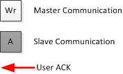
The following abbreviations are used in the descriptions of the transactions,
[S] The start signal on the bus
[ADDR] The address of the slave device
[Rd/R] The read bit asserted after the slave address is put on the bus
[Wr/W] The write bit asserted after the slave address is put on the bus
[A] Acknowledgment
[NA] NACK or No Acknowledgment
[P] The stop signal on the bus
[Sr] Repeated Start
[PEC] Packet Error Check byte
Each transaction (message) description will have an image of the message format; Fig. ref{fig:LEGEND} describes the convention used,
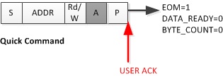
Quick Command
When a Quick Command is received, the EOM (End-of-Message) status bit is set, and the RD_BYTE_COUNT (Received Byte Count) field is 0.
The Slave manually ACKs the transaction by writing to the PMBACK register.
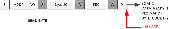
Send Byte
When a Send Byte is received, the DATA_READY and EOM (End-of-Message) status bits are set, and the RD_BYTE_COUNT (Received Byte Count) field is 2, indicating two bytes were received, the data byte and the PEC.
The Slave reads the data and manually ACKs the message by writing to the PMBACK register.
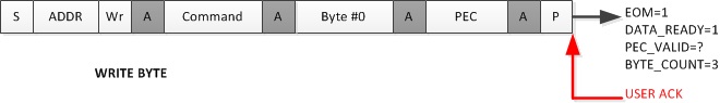
Write Byte
The Write Byte is identical to Send Byte, with the exception that RD_BYTE_COUNT (Received Byte Count) is now 3, that is, a command byte, a data byte and the PEC.
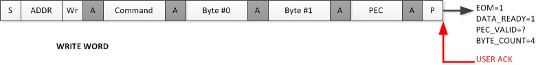
Write Word
The Write Word is identical to Send Byte, with the exception that RD_BYTE_COUNT (Received Byte Count) is 4, that is, a command byte, 2 data bytes and the PEC.
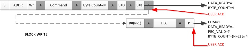
Block Write
The Block Write is issued when the master has to transfer more than 2 data bytes (up to a maximum of 255 bytes). The master will transmit a command, a count (how many bytes it intends to send), followed by the bytes, ending with the PEC.
For every 4 bytes the slave receives, DATA_READY is asserted and RD_BYTE_COUNT is 4; no End-of-Message (EOM) is received at this point. The slave must read the receive buffer and manually ACK reception of 4 bytes before the master can proceed sending the next 4 bytes. On the very last transmission DATA_READY and EOM are asserted, indicating the end of transmission. The slave must read the receive buffer (which has 1 to 4 bytes depending on the initial count) and manually ACK the transaction.
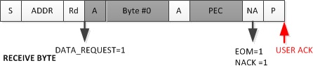
Receive Byte
The master initiates a Receive Byte by putting the slave’s address on the bus followed by a read bit. The slave will automatically ACK its address, load its transmit buffer, and transmit a byte and its PEC.
If there is no error in the transmission the master will NACK the PEC indicating the end of the transaction. Both the NACK and EOM status bits are asserted at this point.
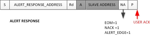
Alert Response
A special variant of the Receive Byte is the Alert Response transactions where the slave device pulls the ALERT line low; the master must respond with the ALERT RESPONSE ADDRESS and a read. The alerting slave will respond by transmitting its own address as shown in Fig. ref{fig:ALERT_RESPONSE}.
When the master puts the Alert Response Address on the line with a read, the alerting slave hardware will automatically respond with its address, without software intervention. \ {color{red} textsc{Note: The 7 bit device address provided by the slave transmit device is placed in the 7 most significant bits of the byte. The eighth bit can be a zero or one.}} \
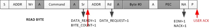
Read Byte
The master initiates a Read Byte by putting the slave’s address on the bus followed by a write bit. The master issues a Read Byte command followed by a repeated start with the slave address and the read bit. When the repeated start is issued on the bus, the DATA_READY bit is asserted at the slave end with a RD_BYTE_COUNT of 1. At the read bit the DATA_REQUEST bit is asserted; the slave responds by transmitting a single byte followed by the PEC. If there is no error in the transmission, the master will NACK the PEC, indicating the end of the transaction. Both the NACK and EOM status bits are asserted at this point.
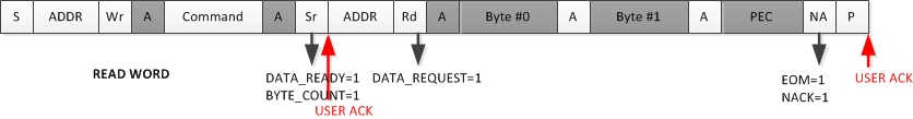
Read Word
Read Word is similar to Read Byte with the exception that the slave responds to the repeated start (read bit) by transmitting two bytes followed by the PEC.
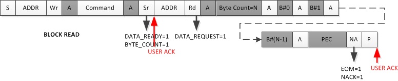
Block Read
If the master transmits a Block Read command, the slave responds by sending more than 2 bytes (up to a maximum of 255 bytes). The transaction, including the status bit assertions, is similar to the read word command. The first byte sent by the slave is always the byte count, that is, the number of bytes it intends to transmit. It then follows this with the data bytes. For every 4 bytes sent by the slave (and acknowledged by the master) the DATA_REQUEST bit is asserted, requesting the slave to send the next set of bytes. The transaction is terminated by the master by issuing a NACK} on the bus; both the NACK and EOM status bits are asserted at the slave end at this point.
Block Write/ Read/ Process Call
This is basically a block write followed by a block read. The key points to note here are the byte counts on the block write and block read must be the same, and a single PEC is sent at the end of the block read.
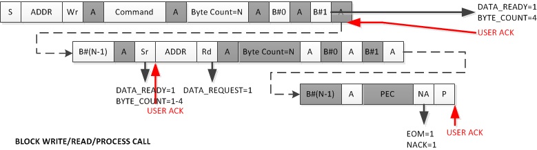
\ {color{red} textsc{Note: A Process call, a write word followed by a read word, falls under the purview of this transaction in the state machine handler}} \
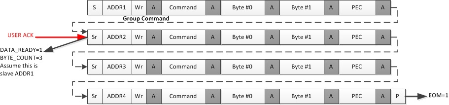
Group Command
The Master writes to a group of slaves in a single transaction. It does this by putting each slave’s address (with a write) followed by a command, two bytes, and a PEC on the bus after a repeated start ( the exception is the first slave address which follows the start). A slave device will acknowledge its address on the bus, and its state machine will respond when the DATA_READY is asserted on the next repeated start (or on a stop, if the slave in question is the last to be addressed).
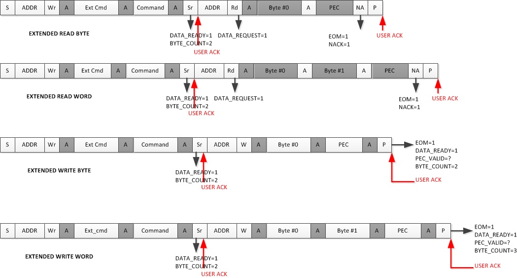
Extended Command
The extended command is supported for four transaction types * Extended Read Byte * Extended Read Word * Extended Write Byte * Extended Write Word
These commands are similar to their non-extended counterparts, with the exception that the command is preceded by the extension byte (0xFE or 0xFF). The master issues a repeated start with the slave address and the read (for a read transaction) or write (for a write transaction) bit asserted. \ {color{red} textsc{Note: This behavior conforms to v1.0 of the PMBus Protocol; v1.2 of the protocol does not require a repeated start (and slave address) after the extension and command bytes are sent} } \ At this point the slave sees the DATA_READY signal asserted and a RD_BYTE_COUNT of 2. It must check the first byte for the extension code before acknowledging. If the transaction is a write the master proceeds; an extended write byte involves 4 bytes: the extension code, the command byte, a data byte, and finally the PEC, whereas a write word transaction involves an additional data byte, making the total 5 bytes. If the transaction is a read, the slave must transfer 1 (read byte) or 2 (read words) bytes depending on the command received, followed by the PEC. \ {color{red} textsc{Note: The PEC is calculated on the slave address (with write bit asserted), the extension, command byte, second slave address (and either read/write bit depending on the transaction), and finally the data byte(s).} } \
The code for this module is contained in driverlib/pmbus.c, with driverlib/pmbus.h containing the API declarations for use by applications.