

|
|
SPI driver implementation for a MSP432E4 SPI controller using the micro DMA controller.
The SPI header file should be included in an application as follows:
Refer to SPI.h for a complete description of APIs & example of use.
This SPI driver implementation is designed to operate on a MSP432E4 SPI controller using a micro DMA controller in ping pong mode. This driver allows for queueing multiple SPI transactions.
This SPI controller supports 4 phase & polarity formats as well as the TI synchronous serial frame format. Refer to the device specific data sheets & technical reference manuals for specifics on each format.
This SPI controller supports a hardware chip select pin. Refer to the device's user manual on how this hardware chip select pin behaves in regards to the SPI frame format.
| Chip select type | SPI_MASTER mode | SPI_SLAVE mode |
|---|---|---|
| Hardware chip select | No action is needed by the application to select the peripheral. | See the device documentation on it's chip select requirements. |
| Software chip select | The application is responsible to ensure that correct SPI slave is selected before performing a SPI_transfer(). | See the device documentation on it's chip select requirements. |
SPI data frames can be any size from 4-bits to 16-bits. If the dataSize in SPI_Params is greater than 8-bits, then the SPIMSP432E4DMA driver will assume that the SPI_Transaction txBuf and rxBuf point to 16-bit (uint16_t) arrays.
| dataSize | buffer element size |
|---|---|
| 4-8 bits | uint8_t |
| 9-16 bits | uint16_t |
Data buffers in transactions (rxBuf & txBuf) must be address aligned according to the data frame size. For example, if data frame is 9-bit or larger (driver assumes buffers are uint16_t) rxBuf & txBuf must be aligned on a 16-bit address boundary.
This driver is designed to make use of the micro DMA for transfers. The driver implementation automatically installs a hardware interrupt service routine for the peripheral on which micro DMA generates IRQ once all data has transfered from memory to the peripheral (TX) or from peripheral to memory (RX).
This driver utilizes DMA channels in ping pong mode (see device TRM) in order to overcome the 1024 item DMA channel limit. This means the driver can execute multi kilo-item transactions without pausing to reconfigure the DMA and causing gaps in transmission. In addition, the driver also allows the user to queue up transfers when opened in SPI_MODE_CALLBACK by calling SPI_transfer() multiple times. Note that each transaction's SPI_Transaction struct must still be persistent and unmodified until that transaction is complete.
Below is an example of queueing three transactions
As this driver uses uDMA to transfer data to/from data buffers, it is the responsibility of the application to ensure that theses buffers reside in memory that is accessible by the DMA.
When SPI_Transaction.rxBuf is NULL, all frames received will be discarded. When SPI_Transaction.txBuf is NULL, an internal scratch buffer is initialized to SPIMSP432E4DMA_HWAttrs.defaultTxBufValue so the uDMA will send some known value.
When used in blocking mode small SPI transfers are can be done by polling the peripheral & sending data frame-by-frame. For master devices this will not block since the transfer can happen immediately. Slaves must exercise caution since the call will poll on the HW until the transfer is complete. For this reason slaves with a transfer timeout will not use polling transfers. The minDmaTransferSize field in the hardware attributes is the threshold; if the transaction count is below the threshold a polling transfer is performed; otherwise a DMA transfer is done. This is intended to reduce the overhead of setting up a DMA transfer to only send a few data frames.
Notes:
#include <stdbool.h>#include <stdint.h>#include <ti/devices/msp432e4/inc/msp432.h>#include <ti/devices/msp432e4/driverlib/pin_map.h>#include <ti/drivers/dma/UDMAMSP432E4.h>#include <ti/drivers/dpl/HwiP.h>#include <ti/drivers/dpl/SemaphoreP.h>#include <ti/drivers/gpio/GPIOMSP432E4.h>#include <ti/drivers/SPI.h>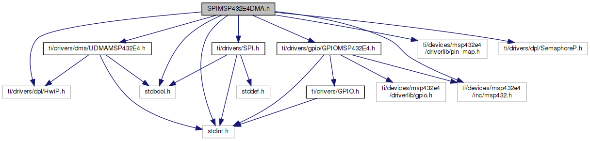
Go to the source code of this file.
Data Structures | |
| struct | SPIMSP432E4DMA_HWAttrs |
| SPIMSP432E4DMA Hardware attributes. More... | |
| struct | SPIMSP432E4DMA_Object |
Macros | |
| #define | SPIMSP432E4_PIN_NO_CONFIG (0xFFFFFFFF) |
| SPIMSP432E4_PIN_NO_CONFIG can be used to inform the SPIMSP432E4DMA driver that a pin should not be configured for use in the SPI bus. If the MOSI pin, MISO pin or FSS is set to SPIMSP432E4_PIN_NO_CONFIG in the SPIMSP432E4DMA_HWAttrs, the pin is not configured to SPI functionality in SPI_open() and the pin can be used for another function. The clkPin cannot be set to SPIMSP432E4_PIN_NO_CONFIG; the clock signal is always required during communication & must be driven by the SPI bus master. More... | |
Variables | |
| const SPI_FxnTable | SPIMSP432E4DMA_fxnTable |
| #define SPIMSP432E4_PIN_NO_CONFIG (0xFFFFFFFF) |
SPIMSP432E4_PIN_NO_CONFIG can be used to inform the SPIMSP432E4DMA driver that a pin should not be configured for use in the SPI bus. If the MOSI pin, MISO pin or FSS is set to SPIMSP432E4_PIN_NO_CONFIG in the SPIMSP432E4DMA_HWAttrs, the pin is not configured to SPI functionality in SPI_open() and the pin can be used for another function. The clkPin cannot be set to SPIMSP432E4_PIN_NO_CONFIG; the clock signal is always required during communication & must be driven by the SPI bus master.
Prevent pin defines from cluttering doxygen
Setting pins to SPIMSP432E4_PIN_NO_CONFIG can be useful in the following situations:
| const SPI_FxnTable SPIMSP432E4DMA_fxnTable |