

|
|
SPI driver implementation for a MSP432E4 SPI controller using the micro DMA controller.
============================================================================
The SPI header file should be included in an application as follows:
Refer to SPI.h for a complete description of APIs & example of use.
This SPI driver implementation is designed to operate on a MSP432E4 SPI controller using a micro DMA controller in ping pong mode. This driver allows for queueing multiple SPI transactions.
This SPI controller supports 4 phase & polarity formats as well as the TI synchronous serial frame format. Refer to the device specific data sheets & technical reference manuals for specifics on each format.
This SPI controller supports a hardware chip select pin. Refer to the device's user manual on how this hardware chip select pin behaves in regards to the SPI frame format.
| Chip select type | SPI_MASTER mode | SPI_SLAVE mode |
|---|---|---|
| Hardware chip select | No action is needed by the application to select the peripheral. | See the device documentation on it's chip select requirements. |
| Software chip select | The application is responsible to ensure that correct SPI slave is selected before performing a SPI_transfer(). | See the device documentation on it's chip select requirements. |
SPI data frames can be any size from 4-bits to 16-bits. If the dataSize in SPI_Params is greater than 8-bits, then the SPIMSP432E4DMA driver will assume that the SPI_Transaction txBuf and rxBuf point to 16-bit (uint16_t) arrays.
| dataSize | buffer element size |
|---|---|
| 4-8 bits | uint8_t |
| 9-16 bits | uint16_t |
Data buffers in transactions (rxBuf & txBuf) must be address aligned according to the data frame size. For example, if data frame is 9-bit or larger (driver assumes buffers are uint16_t) rxBuf & txBuf must be aligned on a 16-bit address boundary.
This driver is designed to make use of the micro DMA for transfers. The driver implementation automatically installs a hardware interrupt service routine for the peripheral on which micro DMA generates IRQ once all data has transfered from memory to the peripheral (TX) or from peripheral to memory (RX).
As this driver uses uDMA to transfer data to/from data buffers, it is the responsibility of the application to ensure that theses buffers reside in memory that is accessible by the DMA.
When rxBuf is NULL, all frames received will be discarded. When txBuf is NULL, an internal scratch buffer is initialized to defaultTxBufValue so the uDMA will send some known value.
When used in blocking mode small SPI transfers are can be done by polling the peripheral & sending data frame-by-frame. This will not block the task which requested the transfer, but instead immediately perform the transfer & return. The minDmaTransferSize field in the hardware attributes is the threshold; if the transaction count is below the threshold a polling transfer is performed; otherwise a DMA transfer is done. This is intended to reduce the overhead of setting up a DMA transfer to only send a few data frames.
Notes:
#include <stdbool.h>#include <stdint.h>#include <ti/devices/msp432e4/inc/msp432.h>#include <ti/devices/msp432e4/driverlib/pin_map.h>#include <ti/drivers/dma/UDMAMSP432E4.h>#include <ti/drivers/dpl/HwiP.h>#include <ti/drivers/dpl/SemaphoreP.h>#include <ti/drivers/gpio/GPIOMSP432E4.h>#include <ti/drivers/SPI.h>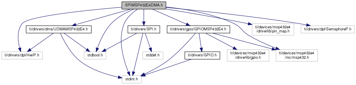
Go to the source code of this file.
Data Structures | |
| struct | SPIMSP432E4DMA_HWAttrs |
| SPIMSP432E4DMA Hardware attributes. More... | |
| struct | SPIMSP432E4DMA_Object |
| SPIMSP432E4DMA Object. More... | |
Macros | |
| #define | SPIMSP432E4_PA2_SSI0CLK GPIOMSP432E4_pinConfigMask(GPIOMSP432E4_PORTA, 2, GPIO_PA2_SSI0CLK) |
| PA2 is used for SSI0CLK. More... | |
| #define | SPIMSP432E4_PA3_SSI0FSS GPIOMSP432E4_pinConfigMask(GPIOMSP432E4_PORTA, 3, GPIO_PA3_SSI0FSS) |
| PA3 is used for SSI0FSS. More... | |
| #define | SPIMSP432E4_PA4_SSI0XDAT0 GPIOMSP432E4_pinConfigMask(GPIOMSP432E4_PORTA, 4, GPIO_PA4_SSI0XDAT0) |
| PA4 is used for SSI0XDAT0. More... | |
| #define | SPIMSP432E4_PA5_SSI0XDAT1 GPIOMSP432E4_pinConfigMask(GPIOMSP432E4_PORTA, 5, GPIO_PA5_SSI0XDAT1) |
| PA5 is used for SSI0XDAT1. More... | |
| #define | SPIMSP432E4_PB5_SSI1CLK GPIOMSP432E4_pinConfigMask(GPIOMSP432E4_PORTB, 5, GPIO_PB5_SSI1CLK) |
| PB5 is used for SSI1CLK. More... | |
| #define | SPIMSP432E4_PB4_SSI1FSS GPIOMSP432E4_pinConfigMask(GPIOMSP432E4_PORTB, 4, GPIO_PB4_SSI1FSS) |
| PB4 is used for SSI1FSS. More... | |
| #define | SPIMSP432E4_PE4_SSI1XDAT0 GPIOMSP432E4_pinConfigMask(GPIOMSP432E4_PORTE, 4, GPIO_PE4_SSI1XDAT0) |
| PE4 is used for SSI1XDAT0. More... | |
| #define | SPIMSP432E4_PE5_SSI1XDAT1 GPIOMSP432E4_pinConfigMask(GPIOMSP432E4_PORTE, 5, GPIO_PE5_SSI1XDAT1) |
| PE5 is used for SSI1XDAT1. More... | |
| #define | SPIMSP432E4_PD3_SSI2CLK GPIOMSP432E4_pinConfigMask(GPIOMSP432E4_PORTD, 3, GPIO_PD3_SSI2CLK) |
| PD3 is used for SSI2CLK. More... | |
| #define | SPIMSP432E4_PG7_SSI2CLK GPIOMSP432E4_pinConfigMask(GPIOMSP432E4_PORTG, 7, GPIO_PG7_SSI2CLK) |
| PG7 is used for SSI2CLK. More... | |
| #define | SPIMSP432E4_PD2_SSI2FSS GPIOMSP432E4_pinConfigMask(GPIOMSP432E4_PORTD, 2, GPIO_PD2_SSI2FSS) |
| PD2 is used for SSI2FSS. More... | |
| #define | SPIMSP432E4_PG6_SSI2FSS GPIOMSP432E4_pinConfigMask(GPIOMSP432E4_PORTG, 6, GPIO_PG6_SSI2FSS) |
| PG6 is used for SSI2FSS. More... | |
| #define | SPIMSP432E4_PD1_SSI2XDAT0 GPIOMSP432E4_pinConfigMask(GPIOMSP432E4_PORTD, 1, GPIO_PD1_SSI2XDAT0) |
| PD1 is used for SSI2XDAT0. More... | |
| #define | SPIMSP432E4_PG5_SSI2XDAT0 GPIOMSP432E4_pinConfigMask(GPIOMSP432E4_PORTG, 5, GPIO_PG5_SSI2XDAT0) |
| PG5 is used for SSI2XDAT0. More... | |
| #define | SPIMSP432E4_PD0_SSI2XDAT1 GPIOMSP432E4_pinConfigMask(GPIOMSP432E4_PORTD, 0, GPIO_PD0_SSI2XDAT1) |
| PD0 is used for SSI2XDAT1. More... | |
| #define | SPIMSP432E4_PG4_SSI2XDAT1 GPIOMSP432E4_pinConfigMask(GPIOMSP432E4_PORTG, 4, GPIO_PG4_SSI2XDAT1) |
| PG4 is used for SSI2XDAT1. More... | |
| #define | SPIMSP432E4_PQ0_SSI3CLK GPIOMSP432E4_pinConfigMask(GPIOMSP432E4_PORTQ, 0, GPIO_PQ0_SSI3CLK) |
| PQ0 is used for SSI3CLK. More... | |
| #define | SPIMSP432E4_PF3_SSI3CLK GPIOMSP432E4_pinConfigMask(GPIOMSP432E4_PORTF, 3, GPIO_PF3_SSI3CLK) |
| PF3 is used for SSI3CLK. More... | |
| #define | SPIMSP432E4_PQ1_SSI3FSS GPIOMSP432E4_pinConfigMask(GPIOMSP432E4_PORTQ, 1, GPIO_PQ1_SSI3FSS) |
| PQ1 is used for SSI3FSS. More... | |
| #define | SPIMSP432E4_PF2_SSI3FSS GPIOMSP432E4_pinConfigMask(GPIOMSP432E4_PORTF, 2, GPIO_PF2_SSI3FSS) |
| PF2 is used for SSI3FSS. More... | |
| #define | SPIMSP432E4_PQ2_SSI3XDAT0 GPIOMSP432E4_pinConfigMask(GPIOMSP432E4_PORTQ, 2, GPIO_PQ2_SSI3XDAT0) |
| PQ2 is used for SSI3XDAT0. More... | |
| #define | SPIMSP432E4_PF1_SSI3XDAT0 GPIOMSP432E4_pinConfigMask(GPIOMSP432E4_PORTF, 1, GPIO_PF1_SSI3XDAT0) |
| PF1 is used for SSI3XDAT0. More... | |
| #define | SPIMSP432E4_PQ3_SSI3XDAT1 GPIOMSP432E4_pinConfigMask(GPIOMSP432E4_PORTQ, 3, GPIO_PQ3_SSI3XDAT1) |
| PQ3 is used for SSI3XDAT1. More... | |
| #define | SPIMSP432E4_PF0_SSI3XDAT1 GPIOMSP432E4_pinConfigMask(GPIOMSP432E4_PORTF, 0, GPIO_PF0_SSI3XDAT1) |
| PF0 is used for SSI3XDAT1. More... | |
| #define | SPIMSP432E4_PIN_NO_CONFIG (0xFFFFFFFF) |
| SPIMSP432E4_PIN_NO_CONFIG can be used to inform the SPIMSP432E4DMA driver that a pin should not be configured for use in the SPI bus. If the MOSI pin, MISO pin or FSS is set to SPIMSP432E4_PIN_NO_CONFIG in the SPIMSP432E4DMA_HWAttrs, the pin is not configured to SPI functionality during SPI_open() and the pin can be used for another function. The clkPin cannot be set to SPIMSP432E4_PIN_NO_CONFIG; the clock signal is always required during communication & must be driven by the SPI bus master. More... | |
Typedefs | |
| typedef struct SPIMSP432E4DMA_HWAttrs | SPIMSP432E4DMA_HWAttrs |
| SPIMSP432E4DMA Hardware attributes. More... | |
| typedef struct SPIMSP432E4DMA_Object | SPIMSP432E4DMA_Object |
| SPIMSP432E4DMA Object. More... | |
Variables | |
| const SPI_FxnTable | SPIMSP432E4DMA_fxnTable |
| #define SPIMSP432E4_PA2_SSI0CLK GPIOMSP432E4_pinConfigMask(GPIOMSP432E4_PORTA, 2, GPIO_PA2_SSI0CLK) |
PA2 is used for SSI0CLK.
| #define SPIMSP432E4_PA3_SSI0FSS GPIOMSP432E4_pinConfigMask(GPIOMSP432E4_PORTA, 3, GPIO_PA3_SSI0FSS) |
PA3 is used for SSI0FSS.
| #define SPIMSP432E4_PA4_SSI0XDAT0 GPIOMSP432E4_pinConfigMask(GPIOMSP432E4_PORTA, 4, GPIO_PA4_SSI0XDAT0) |
PA4 is used for SSI0XDAT0.
| #define SPIMSP432E4_PA5_SSI0XDAT1 GPIOMSP432E4_pinConfigMask(GPIOMSP432E4_PORTA, 5, GPIO_PA5_SSI0XDAT1) |
PA5 is used for SSI0XDAT1.
| #define SPIMSP432E4_PB5_SSI1CLK GPIOMSP432E4_pinConfigMask(GPIOMSP432E4_PORTB, 5, GPIO_PB5_SSI1CLK) |
PB5 is used for SSI1CLK.
| #define SPIMSP432E4_PB4_SSI1FSS GPIOMSP432E4_pinConfigMask(GPIOMSP432E4_PORTB, 4, GPIO_PB4_SSI1FSS) |
PB4 is used for SSI1FSS.
| #define SPIMSP432E4_PE4_SSI1XDAT0 GPIOMSP432E4_pinConfigMask(GPIOMSP432E4_PORTE, 4, GPIO_PE4_SSI1XDAT0) |
PE4 is used for SSI1XDAT0.
| #define SPIMSP432E4_PE5_SSI1XDAT1 GPIOMSP432E4_pinConfigMask(GPIOMSP432E4_PORTE, 5, GPIO_PE5_SSI1XDAT1) |
PE5 is used for SSI1XDAT1.
| #define SPIMSP432E4_PD3_SSI2CLK GPIOMSP432E4_pinConfigMask(GPIOMSP432E4_PORTD, 3, GPIO_PD3_SSI2CLK) |
PD3 is used for SSI2CLK.
| #define SPIMSP432E4_PG7_SSI2CLK GPIOMSP432E4_pinConfigMask(GPIOMSP432E4_PORTG, 7, GPIO_PG7_SSI2CLK) |
PG7 is used for SSI2CLK.
| #define SPIMSP432E4_PD2_SSI2FSS GPIOMSP432E4_pinConfigMask(GPIOMSP432E4_PORTD, 2, GPIO_PD2_SSI2FSS) |
PD2 is used for SSI2FSS.
| #define SPIMSP432E4_PG6_SSI2FSS GPIOMSP432E4_pinConfigMask(GPIOMSP432E4_PORTG, 6, GPIO_PG6_SSI2FSS) |
PG6 is used for SSI2FSS.
| #define SPIMSP432E4_PD1_SSI2XDAT0 GPIOMSP432E4_pinConfigMask(GPIOMSP432E4_PORTD, 1, GPIO_PD1_SSI2XDAT0) |
PD1 is used for SSI2XDAT0.
| #define SPIMSP432E4_PG5_SSI2XDAT0 GPIOMSP432E4_pinConfigMask(GPIOMSP432E4_PORTG, 5, GPIO_PG5_SSI2XDAT0) |
PG5 is used for SSI2XDAT0.
| #define SPIMSP432E4_PD0_SSI2XDAT1 GPIOMSP432E4_pinConfigMask(GPIOMSP432E4_PORTD, 0, GPIO_PD0_SSI2XDAT1) |
PD0 is used for SSI2XDAT1.
| #define SPIMSP432E4_PG4_SSI2XDAT1 GPIOMSP432E4_pinConfigMask(GPIOMSP432E4_PORTG, 4, GPIO_PG4_SSI2XDAT1) |
PG4 is used for SSI2XDAT1.
| #define SPIMSP432E4_PQ0_SSI3CLK GPIOMSP432E4_pinConfigMask(GPIOMSP432E4_PORTQ, 0, GPIO_PQ0_SSI3CLK) |
PQ0 is used for SSI3CLK.
| #define SPIMSP432E4_PF3_SSI3CLK GPIOMSP432E4_pinConfigMask(GPIOMSP432E4_PORTF, 3, GPIO_PF3_SSI3CLK) |
PF3 is used for SSI3CLK.
| #define SPIMSP432E4_PQ1_SSI3FSS GPIOMSP432E4_pinConfigMask(GPIOMSP432E4_PORTQ, 1, GPIO_PQ1_SSI3FSS) |
PQ1 is used for SSI3FSS.
| #define SPIMSP432E4_PF2_SSI3FSS GPIOMSP432E4_pinConfigMask(GPIOMSP432E4_PORTF, 2, GPIO_PF2_SSI3FSS) |
PF2 is used for SSI3FSS.
| #define SPIMSP432E4_PQ2_SSI3XDAT0 GPIOMSP432E4_pinConfigMask(GPIOMSP432E4_PORTQ, 2, GPIO_PQ2_SSI3XDAT0) |
PQ2 is used for SSI3XDAT0.
| #define SPIMSP432E4_PF1_SSI3XDAT0 GPIOMSP432E4_pinConfigMask(GPIOMSP432E4_PORTF, 1, GPIO_PF1_SSI3XDAT0) |
PF1 is used for SSI3XDAT0.
| #define SPIMSP432E4_PQ3_SSI3XDAT1 GPIOMSP432E4_pinConfigMask(GPIOMSP432E4_PORTQ, 3, GPIO_PQ3_SSI3XDAT1) |
PQ3 is used for SSI3XDAT1.
| #define SPIMSP432E4_PF0_SSI3XDAT1 GPIOMSP432E4_pinConfigMask(GPIOMSP432E4_PORTF, 0, GPIO_PF0_SSI3XDAT1) |
PF0 is used for SSI3XDAT1.
| #define SPIMSP432E4_PIN_NO_CONFIG (0xFFFFFFFF) |
SPIMSP432E4_PIN_NO_CONFIG can be used to inform the SPIMSP432E4DMA driver that a pin should not be configured for use in the SPI bus. If the MOSI pin, MISO pin or FSS is set to SPIMSP432E4_PIN_NO_CONFIG in the SPIMSP432E4DMA_HWAttrs, the pin is not configured to SPI functionality during SPI_open() and the pin can be used for another function. The clkPin cannot be set to SPIMSP432E4_PIN_NO_CONFIG; the clock signal is always required during communication & must be driven by the SPI bus master.
Setting pins to SPIMSP432E4_PIN_NO_CONFIG can be useful in the following situations:
| typedef struct SPIMSP432E4DMA_HWAttrs SPIMSP432E4DMA_HWAttrs |
SPIMSP432E4DMA Hardware attributes.
These fields, with the exception of intPriority, are used by driverlib APIs and therefore must be populated by driverlib macro definitions. For MSP432E4 driverlib these definitions are found in:
intPriority is the SPI peripheral's interrupt priority, as defined by the underlying OS. It is passed unmodified to the underlying OS's interrupt handler creation code, so you need to refer to the OS documentation for usage. For example, for SYS/BIOS applications, refer to the ti.sysbios.family.arm.m3.Hwi documentation for SYS/BIOS usage of interrupt priorities. If the driver uses the ti.dpl interface instead of making OS calls directly, then the HwiP port handles the interrupt priority in an OS specific way. In the case of the SYS/BIOS port, intPriority is passed unmodified to Hwi_create().
A sample structure is shown below:
| typedef struct SPIMSP432E4DMA_Object SPIMSP432E4DMA_Object |
SPIMSP432E4DMA Object.
The application must not access any member variables of this structure!
| const SPI_FxnTable SPIMSP432E4DMA_fxnTable |