Application Overview
Z-Stack example applications are designed to enable faster end-product development by providing different implementations of Zigbee device definitions. This allows the developers to explore the usage of the stack for configuring and running a device in a network along with other essential features, such as nonvolatile (NV) memory storage to save the network parameters and application specific information. The configuration and usage of peripherals such as UART, switches, and LEDs are also shown by these sample applications. This chapter explains the application’s implementation to help developers quickly modify the Z-Stack out-of-box example applications for customized development. The following sections detail the example applications of the Z-Stack projects.
- Pre-RTOS initialization
- Application architecture: the Application task which is the lowest priority
task in the system. The code for this task resides in the
ApplicationIDE folder. - Indirect Call Framework: an interface module which abstracts communication between the Stack and other tasks.
Application Architecture
Figure 15. shows the block diagram of the Light and Switch example applications on the CC26x2.
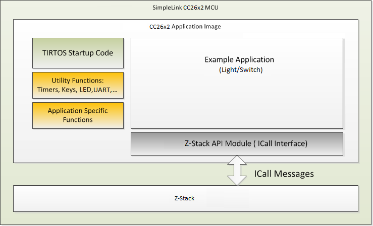
Figure 15. Example Application Block Diagram
High-level descriptions of various blocks in Figure 15. are as follows:
TI-RTOS Start-up Code: Initializes the application (see Start-Up in main() for more details).
Example Application: The platform-independent implementation of the example use case. The Z-Stack out-of-box demonstrates two use cases – Light and Switch. Developers can modify this module’s out-of-box example code for custom for custom application requirements to quickly develop end products.
Utility Functions: Provides various platform utilities which the application can use. Examples include LED, timers, keys, UART and so on.
Application-Specific Functions: Implements platform-specific functions such as data storage over power cycles (nonvolatile) and provides user interface functions, such as handling button presses or displaying essential information on the UART.
Z-Stack API Module (API Z-Stack Module): This module provides an interface to the management and data services of the Zigbee stack through the Indirect Call Framework (ICALL) module. The ICALL module is described in Indirect Call Framework.
Application Preprocessor Configuration
The following table contains the preprocessor symbols which can be added or removed pertaining to device operation. They are located in the Project Properties as further discussed in the Useful CCS IDE Settings section of the Z-Stack Quick Start Guide.
| Symbol | Description | Modifiable? |
|---|---|---|
| BDB_FINDING_BINDING_CAPABILITY_ENABLED | Set to zero to disable BDB F&B | Y |
| BDB_REPORTING | Allows automatic cluster attibute reporting | Y |
| BDB_TL_INITIATOR | Device is a Touchlink Initiator | Y |
| BDB_TL_TARGET | Device is a Touchlink Target | Y |
| BOARD_DISPLAY_USE_UART | Use UART communication for application information | Y |
| CC13X2R1_LAUNCHXL | LaunchPad variant, may be changed when migrating to a custom development board | Y |
| COMBO_MAC | MAC radio configuration | N |
| CONFIG_PA_TYPE | Set to APIMAC_HIGH_PA for the internal power amplifier, otherwise APIMAC_DEFAULT_PA | Y |
| DeviceFamily_CC13X2 | Select the chipset | N |
| DEVICE_FAMILY | Select the chipset | N |
| FEATURE_NON_BEACON_MODE | Standard beacon type per the Zigbee specification | N |
| FREQ_2_4G | Frequency to be used, only 2.4 GHz is supported | N |
| HAL_ASSERT_SPIN | Management of HAL asserts | Y |
| HEAPMGR_SIZE | Size of the heap | Y |
| ICALL_HOOK_ABORT_FUNC | Function abort for ICall handling | N |
| ICALL_MAX_NUM_TASKS | Maximum tasks to be handled by ICall | Y |
| MT_[FUNC] | Function enabled for the MT interface | Y |
| NPI_FLOW_CTRL | Enables CTS/RTS for UART transportation | Y |
| NPI_UART | Use UART communication for ZNP processing | Y |
| NV_INIT | Store network settings in non-volatile memory | Y |
| NV_RESTORE | Restore previous network settings on start-up | Y |
| OAD_KEEP_NV_PAGES | Whether or not to keep NV pages during OTA update | Y |
| OTA_HA | Using the application for HA OTA updates | Y |
| OTA_SERVER | Application is an OTA server for host interaction Define as TRUE or FALSE | Y |
| RCN_APP_ASSERT | Set asserts for the app | Y |
| SET_CCFG_BL_CONFIG | Bootloader configurations | Y |
| STACK_LIBRARY | Use the TI 15.4 MAC library | N |
| TC_LINKKEY_JOIN | Check if a specific device has been authenticated | N |
| USE_ICALL | Initialize and use ICall layer | N |
| xdc_runtime | Compile options for RTOS | N |
| ZAPP_P[1/2] | Determine which UART[0/1] to use for application | Y |
| ZCL_[CLUSTER NAME] | Zigbee clusters allowed by the application | Y |
| ZCL_[READ/WRITE/ETC] | Ability to process ZCL foundation incoming command and response messages | Y |
| ZTOOL_P[1/2] | Determine which UART[0/1] to use for ZNP | Y |
| ZNP_NPI | If the device is a Zigbee Network Processor | Y |
Note
Please refer to the preprocessor symbols section of the Z-Stack Quick Start Guide to setup compile options for the project if using IAR.
Start-Up in main()
The main() function inside of main.c is the application starting
point at runtime. This is where the board is brought up with interrupts
disabled and board-related components are initialized.
Tasks in this function are configured by initializing the
necessary parameters, setting their priority, and initializing the stack size
for the application. In the final step, interrupts are enabled and the
SYS/BIOS kernel scheduler is started by calling BIOS_start(),
which does not return. See the CC26x2 Technical Reference Manual for information on the start-up sequence
before main() is reached.
Void main()
{
    Task_Params taskParams;

#ifndef USE_DEFAULT_USER_CFG
    user0Cfg[0].pAssertFP = macHalAssertHandler;
#endif

    /* enable iCache prefetching */
    VIMSConfigure(VIMS_BASE, TRUE, TRUE);

#if defined(USE_CACHE_RAM)
    /* Disable cache */
    VIMSModeSet( VIMS_BASE, VIMS_MODE_DISABLED);
#else
    /* Enable cache */
    VIMSModeSet( VIMS_BASE, VIMS_MODE_ENABLED);
#endif

    /*
     Initialization for board related stuff such as LEDs
     following TI-RTOS convention
     */
#if defined(CC13X2R1_LAUNCHXL) && !defined(NO_CC1312R1_SUPPORT) && !defined(NO_CC1352P1_SUPPORT)
  CC13X2R1_LAUNCHXL_Pin_init();
#else
  PIN_init(BoardGpioInitTable);
#endif

    /* Configure task. */
    Task_Params_init(&taskParams);
    taskParams.stack = myTaskStack;
    taskParams.stackSize = APP_TASK_STACK_SIZE;
    taskParams.priority = 1;
    Task_construct(&myTask, taskFxn, &taskParams, NULL);

#ifdef DEBUG_SW_TRACE
    IOCPortConfigureSet(IOID_8, IOC_PORT_RFC_TRC, IOC_STD_OUTPUT
                    | IOC_CURRENT_4MA | IOC_SLEW_ENABLE);
#endif /* DEBUG_SW_TRACE */

    BIOS_start(); /* enable interrupts and start SYS/BIOS */
}
In terms of the IDE workspace, main.c exists in the Application project –
meaning that when compiled it is placed in the allocated section of the application’s flash.
Application Initialization Function
Tasks describes how a task is constructed. After the
task is constructed
and the SYS/BIOS kernel scheduler is started, the function that was passed
during task construction is run when the task is ready. Power-management
functions are initialized here and the ICALL module is initialized
through ICall_init(). The primary IEEE address (programmed by TI) is
obtained from the CCFG area of the flash memory and NV drivers are
initialized, then the application task is initialized and started.
Void taskFxn(UArg a0, UArg a1)
{

    /*
     Disallow shutting down JTAG, VIMS, SYSBUS during idle state
     since TIMAC requires SYSBUS during idle.
     */
    Power_setConstraint(PowerCC26XX_IDLE_PD_DISALLOW);

#if defined(USE_CACHE_RAM)
    /* Retain the Cache RAM */
    Power_setConstraint(PowerCC26XX_SB_VIMS_CACHE_RETAIN);
#endif

    /* Initialize ICall module */
    ICall_init();

    /*
     * Copy the extended address from the CCFG area
     * Assumption: the memory in CCFG_IEEE_MAC_0 and CCFG_IEEE_MAC_1
     * is contiguous and LSB first.
     */

    memcpy(zstack_user0Cfg.extendedAddress, (uint8_t *)&(__ccfg.CCFG_IEEE_MAC_0),
           (APIMAC_SADDR_EXT_LEN));

    /* Check to see if the CCFG IEEE is valid */
    if(memcmp(zstack_user0Cfg.extendedAddress, dummyExtAddr, APIMAC_SADDR_EXT_LEN) == 0)
    {
        /* No, it isn't valid.  Get the Primary IEEE Address */
        memcpy(zstack_user0Cfg.extendedAddress, (uint8_t *)(FCFG1_BASE + EXTADDR_OFFSET),
                       (APIMAC_SADDR_EXT_LEN));
    }


#ifdef NV_RESTORE
    /* Setup the NV driver */
#ifdef ONE_PAGE_NV
    NVOCOP_loadApiPtrs(&zstack_user0Cfg.nvFps);
#else
    NVOCTP_loadApiPtrs(&zstack_user0Cfg.nvFps);
#endif

    if(zstack_user0Cfg.nvFps.initNV)
    {
        zstack_user0Cfg.nvFps.initNV( NULL);
    }
#endif


    /* Start tasks of external images */
    ICall_createRemoteTasks();

    /* Kick off application */
    zclSampleLight_task(&zstack_user0Cfg.nvFps);
}
For example, in the Light application main calls taskfnx(),
which later calls zclSampleLight_task that serves as the entrance for
the application code to configure Z-Stack network parameters as well as
application specific peripherals configurations, callbacks, and stack
notifications. Some examples are:
- Timers initialization.
- Button and LEDs.
- Register the application endpoint, clusters, and attributes.
- Register for callbacks to process general clusters commands.
- Initialize network configuration parameters.
- Register for ZDO callbacks.
- Initialize the serial UI.
Event Processing in the Task Function
After initializing the peripherals and configuring the application and
implementing the initialization function from the previous code snippet,
zclSampleLight_task(), it enters an infinite loop so as to continuously
process as an independent task and not run to completion, seen
in Figure 16..
![@startuml
:zclSampleLight_task();
:zclSampleLight_initialization()]
:zclSampleLight_process_loop()]
repeat
while(Process Z-Stack messages)
:Process Application peripheral events]
:Process Application events]
endwhile (No events to process)
repeat while
@enduml](../_images/plantuml-3382cc48459394ea87a23834e9e9c516d026253d.png)
Figure 16. Light Example Application Task Flow Chart
Figure 16. shows various reasons for posting to the semaphore, causing the task to become active.
Events Signaled Through the Internal Event Variable
The Application task uses an event variable bit mask to identify what action caused the process to wake up and take appropriate action. Each bit of the event variable corresponds to a defined event such as:
/*! Event ID - Event ID to update the light level */
#define SAMPLELIGHT_LEVEL_CTRL_EVT 0x0002

/*! Event ID - Event ID for end devices to perform a rejoin if parent device is not reachable */
#define SAMPLEAPP_END_DEVICE_REJOIN_EVT 0x0004
Whichever function sets this bit in the event variable must also ensure to post to the semaphore to wake up the application for processing. An example of this is the clock handler for clock timeouts.
static void zclSampleLight_processLevelControlTimeoutCallback(UArg a0)
{
    (void)a0; // Parameter is not used

    events |= SAMPLELIGHT_LEVEL_CTRL_EVT;

    // Wake up the application thread when it waits for clock event
    Semaphore_post(sem);
}
Which is later handled and the event bit is cleared as the event got processed.
if(events & SAMPLELIGHT_LEVEL_CTRL_EVT)
{
    zclSampleLight_AdjustLightLevel();
    events &= ~SAMPLELIGHT_LEVEL_CTRL_EVT;
}
When adding an event, it must be unique for the given task and be a power of 2
(so that only 1 bit is set). Because the event variable is initialized as
uint16_t, this setup allows for a maximum of 16 internal events.
Callbacks
The application code also likely includes various callbacks from the protocol
stack layer and RTOS modules. To ensure thread safety, processing should be
minimized in the actual callback and the bulk of the processing should be done
in the application context. The following code snippet shows how the events
and callbacks from the stack are processed, the stack notifications are
redirected to zclSampleLight_processZStackMsgs(), and the application
events are directly processed here.
static void zclSampleLight_process_loop(void)
{
    /* Forever loop */
    for(;;)
    {
        ICall_ServiceEnum stackid;
        ICall_EntityID dest;
        zstackmsg_genericReq_t *pMsg = NULL;

        /* Wait for response message */
        if(ICall_wait(ICALL_TIMEOUT_FOREVER) == ICALL_ERRNO_SUCCESS)
        {
            /* Retrieve the response message */
            if(ICall_fetchServiceMsg(&stackid, &dest, (void **)&pMsg)
               == ICALL_ERRNO_SUCCESS)
            {
                if( (stackid == ICALL_SERVICE_CLASS_ZSTACK)
                    && (dest == zclSampleLight_Entity) )
                {
                    if(pMsg)
                    {
                        zclSampleLight_processZStackMsgs(pMsg);

                        // Free any separately allocated memory
                        Zstackapi_freeIndMsg(pMsg);
                    }
                }

                if(pMsg)
                {
                    ICall_freeMsg(pMsg);
                }
            }

            if(events & SAMPLEAPP_KEY_EVT)
            {
                // Process Key Presses
                zclSampleLight_processKey(keys);
                keys = 0;
                events &= ~SAMPLEAPP_KEY_EVT;
            }

            if(events & SAMPLEAPP_UI_AUTO_REFRESH_EVT)
            {
                UI_Refresh();
                events &= ~SAMPLEAPP_UI_AUTO_REFRESH_EVT;
            }

            if(events & SAMPLEAPP_UI_INPUT_EVT)
            {
                zclSampleAppsUI_ProcessUART();
                events &= ~SAMPLEAPP_UI_INPUT_EVT;
            }

#ifdef ZCL_LEVEL_CTRL
            if(events & SAMPLELIGHT_LEVEL_CTRL_EVT)
            {
                zclSampleLight_AdjustLightLevel();
                events &= ~SAMPLELIGHT_LEVEL_CTRL_EVT;
            }
#endif // ZCL_LEVEL_CTRL

#if !defined (DISABLE_GREENPOWER_BASIC_PROXY) && (ZG_BUILD_RTR_TYPE)
            if(events & SAMPLEAPP_PROCESS_GP_DATA_SEND_EVT)
            {
                zcl_gpSendNotification();
                events &= ~SAMPLEAPP_PROCESS_GP_DATA_SEND_EVT;
            }

            if(events & SAMPLEAPP_PROCESS_GP_EXPIRE_DUPLICATE_EVT)
            {
                gp_expireDuplicateFiltering();
                events &= ~SAMPLEAPP_PROCESS_GP_EXPIRE_DUPLICATE_EVT;
            }
#endif

#if ZG_BUILD_ENDDEVICE_TYPE
            if ( events & SAMPLEAPP_END_DEVICE_REJOIN_EVT )
            {
              zstack_bdbZedAttemptRecoverNwkRsp_t zstack_bdbZedAttemptRecoverNwkRsp;

              Zstackapi_bdbZedAttemptRecoverNwkReq(zclSampleLight_Entity,&zstack_bdbZedAttemptRecoverNwkRsp);

              events &= ~SAMPLEAPP_END_DEVICE_REJOIN_EVT;
            }
#endif
        }
    }
}
Stack notifications are meant to provide context to the application to take some decisions and notify the stack, if required. An example of this is the BDB Filter Networks Descriptors indication shown below:
case zstackmsg_CmdIDs_BDB_FILTER_NWK_DESCRIPTOR_IND:

    /*   User logic to remove networks that do not want to join
     *   Networks to be removed can be released with Zstackapi_bdbNwkDescFreeReq
     */
    Zstackapi_bdbFilterNwkDescComplete(zclSampleLight_Entity);

break;
In this case the message contained in the notification carries the network descriptor
of the networks found during the commissioning process. The application is in charge
of removing those networks that are not meant to be joined (if the application is
willing to join specific networks) by calling Zstackapi_bdbNwkDescFreeReq()
to remove the network descriptor. After the filtering is done, the application must
indicate to the stack that it has to process the remaining network descriptors (even
if all the network descriptors has been removed) by calling
Zstackapi_bdbFilterNwkDescComplete() so that the stack may continues with its process.
Other stack notifications can be handled by application logic to update the application state, such as Base Device Behavior BDB notifications, which provides status of the previous commissioning requests from the application.
case zstackmsg_CmdIDs_BDB_NOTIFICATION:
    {

        zstackmsg_bdbNotificationInd_t *pInd;
        pInd = (zstackmsg_bdbNotificationInd_t*)pMsg;
        zclSampleLight_ProcessCommissioningStatus(&(pInd->Req));
    }
break;
Asynchronous Z-Stack Callbacks must be registered through ICAll by calling
Zstackapi_DevZDOCBReq() with the correct fields set to true in a
zstack_devZDOCBReq_t. For example, if you would like to receive device state change
notifications then the following must be called from zclSampleLight_Init
static void SetupZStackCallbacks(void)
{
    zstack_devZDOCBReq_t zdoCBReq = {0};

    // Register for Callbacks, turn on:
    //  Device State Change,
    //  ZDO Match Descriptor Response,
    zdoCBReq.has_devStateChange = true;
    zdoCBReq.devStateChange = true;

    (void)Zstackapi_DevZDOCBReq(zclSampleLight_Entity, &zdoCBReq);
}
Afterwards it can be handled in a zclSampleLight_processZStackMsgs() case statement.
More information is provided in the Z-Stack API.
case zstackmsg_CmdIDs_DEV_STATE_CHANGE_IND:
{
    // The ZStack Thread is indicating a State change
    zstackmsg_devStateChangeInd_t *pInd =
        (zstackmsg_devStateChangeInd_t *)pMsg;
          UI_DeviceStateUpdated(&(pInd->req));
}
break;
Indirect Call Framework
ICALL is a module that provides a mechanism for the Application to interface with Z-Stack services (such as Z-Stack APIs), as well as certain primitive services (such as thread synchronization) provided by the real-time operating system (RTOS). ICALL allows both the Application and protocol stack tasks to efficiently operate, communicate, and share resources in a unified RTOS environment.
The central component of the ICALL architecture is the dispatcher, which facilitates the application program interface between the Application and the Z-Stack task. Although most of the ICALL interactions are abstracted within the Z-Stack APIs, it is important for the application developer to understand the underlying architecture so that proper Z-Stack protocol stack operation is achieved in the multithreaded RTOS environment. The source code of the ICALL module is provided in the ICALL IDE folder in the Application project.
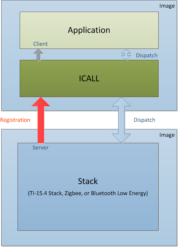
Figure 17. ICALL Application – Protocol Stack Abstraction
ICALL Protocol Stack Service
As depicted in Figure 17., the ICALL core use case involves messages between a server entity (the Z-Stack task) and a client entity (the Application task). The reasoning for this architecture is twofold: to enable independent updating of the application and Z-Stack, and to maintain API consistency as the software is ported from legacy platforms (for example OSAL for the CC253x) to the CC26x2 TI-RTOS. The ICALL Z-Stack Service serves as the Application interface to all Z-Stack APIs. Internally, when a Z-Stack protocol stack API is called by the Application, the ICALL module routes (dispatches) the command to the Z-Stack, and where appropriate, routes messages from the Z-Stack to the Application.
Because the ICALL module is part of the Application project, the Application task can access the ICALL with direct function calls. User modifications to the ICALL source are not encouraged. Also, because the Z-Stack executes at the highest priority, the Application task blocks until the response is received. Certain protocol stack APIs may respond immediately; however, the Application thread blocks because the API is being dispatched to the Z-Stack through the ICALL. Other Z-Stack APIs (such as event updates) may also respond asynchronously to the Application through the ICALL, with the response sent to the task event handler of the Application.
ICALL Primitive Service
ICALL includes a primitive service that abstracts various operating system-related functions. Due to shared resources, and to maintain interprocess communication, the Application must use the following ICALL primitive service functions.
- Messaging and Thread Synchronization
- Heap Allocation and Management
Messaging and Thread Synchronization
The messaging and thread synchronization functions provided by the ICALL let users design an application to protocol stack interface in the multithreaded RTOS environment. Within the ICALL, messaging between two tasks is achieved by sending a message block from one thread to the other using a message queue. The sender allocates memory, writes the content of the message into the memory block, and then sends (enqueues) the memory block to the recipient. Notification of message delivery is accomplished using a signaling semaphore. The receiver wakes up on the semaphore, copies the message memory block (or blocks), processes the message, and returns (frees) the memory block to the heap.
The Stack uses the ICALL for notifying and sending messages to the Application. These service messages (such as state change notifications) received by the Application task are delivered by the ICALL and processed in the task context of the Application.
Heap Allocation and Management
The ICALL provides the Application with global heap APIs for dynamic
memory allocation. The size of the ICALL heap is configured with the
HEAPMGR_SIZE preprocessor define in the Application project. ICALL uses
this heap for all protocol stack messaging as well as to obtain memory for other
ICALL services. TI recommends that the Application uses these
ICALL APIs for dynamic memory allocation within the Application.
ICALL Initialization and Registration
To instantiate and initialize the ICALL service, the following functions
must be called by the application in main() before starting the SYS/BIOS
kernel scheduler.
/* Initialize ICall module */
ICall_init();

/* Start tasks of external images - Priority 5 */
ICall_createRemoteTasks();
Calling ICall_init() initializes the ICALL primitive service
(for example, heap manager) and framework. Calling
ICall_createRemoteTasks() creates, but does not start, the Z-Stack
protocol stack task.
Before using ICALL protocol services, both the server and client must
enroll and register with the ICALL. The server enrolls a service which
is enumerated at build time. Service function handler registration uses a
globally defined unique identifier for each service. For example, Z-Stack uses
ICALL_SERVICE_CLASS_ZSTACK for receiving Z-Stack protocol stack messages
through the ICALL.
The following is a call to enroll the Z-Stack protocol stack service (server)
with the ICALL in zstacktask.c
/* ICall enrollment */
/* Enroll the service that this stack represents */
ICall_enrollService( ICALL_SERVICE_CLASS_ZSTACK, NULL, &ZStackEntity, &ZStackSem );
The registration mechanism is used by the client to send and receive messages
through the ICALL dispatcher. For a client (for example, Application
task) to use the Z-Stack APIs, the client must first register its task with the
ICALL. This registration is done for the application in
zclSampleLight_initialization(), which is called by the applications initialization
functions. The following is the call to the ICALL in zclSampleLight_initialization()
in zcl_samplelight.c
// Register the current thread as an ICall dispatcher application
// so that the application can send and receive messages.
ICall_registerApp(&zclSampleLight_Entity, &sem);
zcl_samplelight.c supplies the zclSampleLight_Entity and sem inputs
which, upon return of ICall_registerApp(), are initialized for the
client (for example, Application) task. These objects are subsequently used by
the ICALL to facilitate messages between the Application and server
tasks. The sem argument represents the semaphore used for signaling,
whereas the zclSampleLight_Entity represents the task destination message
queue. Each task registering with the ICALL has unique sem and
zclSampleLight_Entity identifiers.
ICALL Thread Synchronization
The ICALL module switches between Application and Stack threads through
the use of preemption and semaphore synchronization services provided by the
RTOS. The two ICALL functions to retrieve and enqueue messages are not
blocking functions. They check whether there is a received message in the queue,
and if there is no message then the functions return immediately with the
ICALL_ERRNO_NOMSG value. To allow a client or a server thread to
block until it receives a message, ICALL provides the following function
which blocks until the semaphore associated with the caller RTOS thread is
posted.
//static inline ICall_Errno ICall_wait(uint_fast32_t milliseconds)
ICall_Errno errno = ICall_wait(ICALL_TIMEOUT_FOREVER);
In the preceding function, milliseconds is the timeout period in ms, after which
ICALL_ERRNO_TIMEOUT is returned if the function has not already completed.
If ICALL_TIMEOUT_FOREVER is passed as ms, ICall_wait() shall block
forever or until the semaphore is posted.
Allowing an application or a server thread to block yields the
processor resource to other lower priority threads, or conserves energy by
shutting down power and clock domains whenever possible. The semaphore
associated with an RTOS thread is signaled by either of the following
conditions.
- A new message is queued to the Application RTOS thread queue.
ICall_signal()is called for the semaphore.
ICall_signal() is provided so that an application or a server can add
its own event to unblock ICall_wait() and synchronize the thread.
ICall_signal() accepts a semaphore handle as its sole argument as follows.
//static inline ICall_Errno ICall_signal(ICall_Semaphore msgsem)
ICall_signal(sem);
The semaphore handle associated with the thread is obtained through either the
ICall_enrollService() call or ICall_registerApp() call.
Note
It is not possible to call an ICALL function from a stack callback. This action causes the
ICALL to abort (with ICall_abort()) and breaks the system.
Example ICALL Usage
Figure 18. shows an example command being sent from
the application to the Z-Stack through the ICALL, with a corresponding
return value passed back to the application. ICall_init() initializes
the ICALL module instance itself and ICall_createRemoteTasks()
creates a task per external image, with an entry function at a known address.
After initializing the ICALL, the Application task registers with the
ICALL using ICall_registerApp. After the SYS/BIOS
scheduler starts and the Application task runs, the application sends a protocol
command defined in zstackapi.c such as Zstackapi_bdbSetAttributesReq().
The protocol command is not executed in the application thread. Instead the
command is encapsulated in an ICALL message and routed to the Z-Stack
task through the ICALL. In other words, this command is sent to the
ICALL dispatcher where it is dispatched and executed on the server side
(Z-Stack). The Application thread meanwhile blocks (waits for) the corresponding
command status message (status). When the Z-Stack protocol stack finishes
executing the command, the command status message response is sent through the
ICALL back to the application thread.
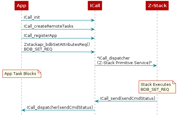
Figure 18. ICall Messaging Example
System Stack
Besides the RTOS and ICall heaps previously mentioned, there are other sections of memory to consider. As described in TI-RTOS (RTOS Kernel) Overview, each task has its own runtime stack for context switching. Furthermore, another runtime stack is used by the RTOS for main(), HWIs, and SWIs. This system stack is allocated in the Application linker file, to be placed at the end of the RAM of the Application.
For CCS, the RTOS system stack is defined by the Program.stack parameter in the app.cfg RTOS configuration file.
/* main() and Hwi, Swi stack size */
Program.stack = 1280;
Then the RTOS system stack is placed by the linker in the RAM space of the Application::
/* Create global constant that points to top of stack */
/* CCS: Change stack size under Project Properties */
STACK_TOP = stack + STACK_SIZE;
Common User Interface
It is recommended to use PuTTY as the serial terminal program for these sample applications because the serial output has been verified to be formatted correctly in this program. For serial port setup, select 115200 for baud rate and disable flow control.
The user interface allows to control the commissioning configuration as well as
application behavior. The commissioning interface is common for all
applications and is implemented in the module zcl_sampleapps_ui.c/.h.
The application specifics of the serial interface is implemented in its respective application files.
The user interface consist in a series of circular menus that can be navigated using the keys ‘a’ and ‘d’ to move from one menu to another. The key ‘e’ is then used to get into a submenu. The keys ‘w’ and ‘s’ are used to change the parameters on the menu such as when setting the channel mask, PAN ID, install codes, etc.
Note
The interface is not case sensitive.
The common user interface is also dependent on the capabilities of the compiled device, e.g. Trust Center devices (coordinators) will require the IEEE address of the joining device when introducing Install Codes, whereas router or end devices will only require the install code as the IEEE address is of itself. Figure 19. shows the common menus for all sample applications.
![@startuml
state ApplicationUI {
state "App Menu" as AppMenu
state "Reset FN" as ResetFN
state "Add Install Code" as AddIC
state "Set Install Code" as SetIC
state "Set Install Code Address" as SetICA
state "Finding and Binding" as FnB
state "Primary Channel Mask" as primChanMask
state "Secondary Channel Mask" as secChanMask
state "Apply Install Code" as ApplyIC
state "Back" as BackConfigure
state "Back" as BackAddIC
[*] -> Welcome
Welcome -> Configure
Welcome -down-> Help : Select
Configure -> Commissioning
Configure --> AddIC : Select
Commissioning -> AppMenu
AppMenu -> Info
note top of AppMenu: Application Specific Menu\n(Press Select)
Info -> ResetFN
ResetFN -> [*]
AddIC -down-> Formation
AddIC -> SetIC : Select
Formation -down-> Steering
Steering -down-> FnB
FnB -down-> primChanMask
primChanMask -down-> secChanMask
secChanMask -down-> PanID
PanID -down-> BackConfigure
BackConfigure -> Configure : Select
SetIC -> SetICA
SetICA -> ApplyIC
ApplyIC -> BackAddIC
BackAddIC -> AddIC : Select
}
@enduml](../_images/plantuml-f0a4cd2526102e5b4ed2bc13ef59f17ba6d4233b.png)
Figure 19. Common Sample Application Screens
The common user interface also allows interaction with the specific application menu system under the App menu screen.
Welcome and <Help> Screens
The Welcome Screen (Figure 20.) displays the application name and leads to the Help Screen (Figure 21.), which outlines the generic functionality of the keys throughout the application. The following sections describe the specific functionality of the keys for each menu screen. In the Help screen, ‘a’, ‘d’, ‘w’ ’s’ symbolize Left, Right, Up and Down buttons, respectively. ‘e’ is used as execute/set/enter.
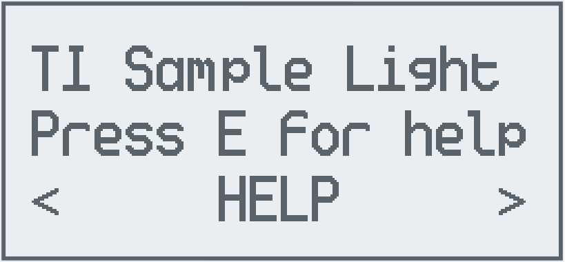
Figure 20. Welcome screen
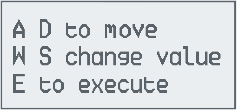
Figure 21. Help screen
| Welcome and Help Screens | ||
|---|---|---|
| Key | Functionality | Comment |
| a/d | Menu navigation | Move to previous/next screen |
| e | Help | Press e to show the help screen, press e again to go back to the Welcome Screen |
<Info> Screen
The info screen (Figure 22.) displays the available information about the device such as the IEEE address, the PAN ID, the channel, short address, logical device, and the parent short address.
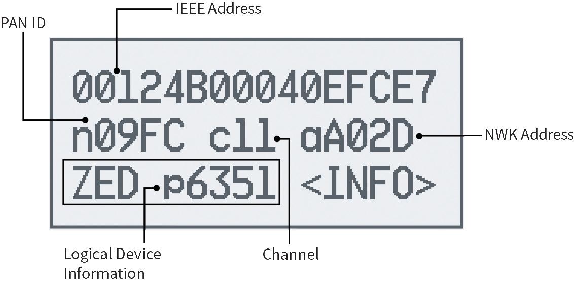
Figure 22. Info screen example
<Configure> Menu
The Configure Menu (Figure 23.) contains several sub-menus that allow the user to manipulate the install codes, commissioning procedures, channel masks and PAN ID. This configuration will define the device behavior during BDB commissioning procedures.
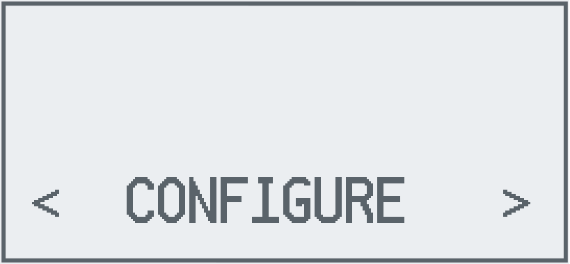
Figure 23. Configure Menu
<Add Instl Code> Menu
The Add Install Code Menu (Figure 24.) provides a user interface to set install codes. The same install code must be applied to both the Trust Center and the joining device before attempting to join. These devices will use this install code to generate the TCLK. Joining devices can only store a single install code at a time, but a Trust Center can store multiple install codes and corresponding IEEE addresses for joining devices. Pressing ‘e’ key while on this screen enters the Install-Code menu, which has two sub-screens for a Trust Center, and one for joining devices.
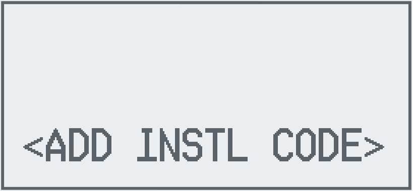
Figure 24. Add Install Code Screen
<Set Instl Code> Screen
The Set Install Code Screen (Figure 25.) has two modes of operation, view and edit. In the view mode, the install code is shown in the first two lines. The edit mode allows changing the default install code to any desired value. In edit mode, the CRC of the install code is also displayed, on the left side of the third line.
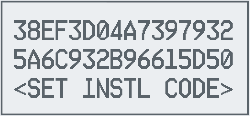
Figure 25. Set Install Code Screen
| <Set Instl Code> Screen - view mode | ||
|---|---|---|
| Key | Functionality | Comment |
| a/d | Menu navigation | Move to previous/next screen |
| e | Select | Enter edit mode |
| <Set Instl Code> Screen - edit mode | ||
|---|---|---|
| Key | Functionality | Comment |
| a/d | Digit navigation | Move to previous/next digit |
| w/s | Value change | Increase/decrease the value of the highlighted digit |
| e | Select | Save and exit mode |
Note that the Apply Install Code Screen must be used to apply the altered install codes.
<Set I.C. Addr> Screen
The Set Install Code Address Screen (Figure 26.) is only available for a Trust Center and has two modes of operation. In the first mode, the IEEE address to be associated with the install code entered in the previous screen is shown. The second mode allows this address to be changed. When a device with this IEEE address tries to join the Trust Center, the Trust Center will use the associated Install Code to generate a Trust Center Link Key to use with this device.
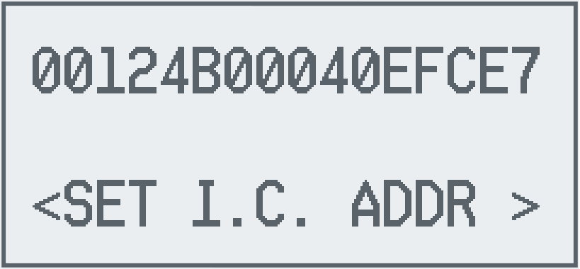
Figure 26. Set Install Code Address Screen (Trust Center only)
| <Set I.C. Addr> Screen - view mode | ||
|---|---|---|
| Key | Functionality | Comment |
| a/d | Menu navigation | Move to previous/next screen |
| e | Select | Enter edit mode |
| <Set I.C. Addr> Screen - edit mode | ||
|---|---|---|
| Key | Functionality | Comment |
| a/d | Digit navigation | Move to previous/next digit |
| w/s | Value change | Increase/decrease the value of the highlighted digit |
| e | Select | Save and exit mode |
Apply Install Code Screen
Apply Install Code Screen (Figure 27.) will save the last configuration done for remote nodes in the case of a Trust Center, or local configuration for routers and end devices. The last status must be successful to ensure the correct application of install code.
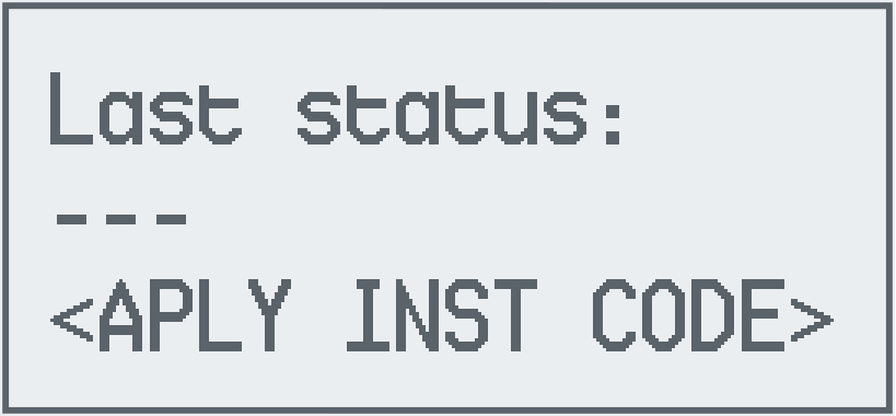
Figure 27. Apply Install Code screen
| <Aply Inst Code> Screen | ||
|---|---|---|
| Key | Functionality | Comment |
| a/d | Menu navigation | Move to previous/next screen |
| e | Select | Apply the install code configured in the previous screens |
Channel Mask Screens
Channel Mask Screens (Figure 28., Figure 29.) display and allow modification of the default channel configuration of the device for primary and secondary channel mask. Channels marked with * are enabled in the selected channel mask. Just press the ‘e’ key to start changing the mask.
The display numbers in the channel mask are read as follows:
| Channel mask conversion | ||||||||||||||||
|---|---|---|---|---|---|---|---|---|---|---|---|---|---|---|---|---|
| Logical Channel | 11 | 12 | 13 | 14 | 15 | 16 | 17 | 18 | 19 | 20 | 21 | 22 | 23 | 24 | 25 | 26 |
| Displayed Digit | 1 | 2 | 3 | 4 | 5 | 6 | 7 | 8 | 9 | 0 | 1 | 2 | 3 | 4 | 5 | 6 |
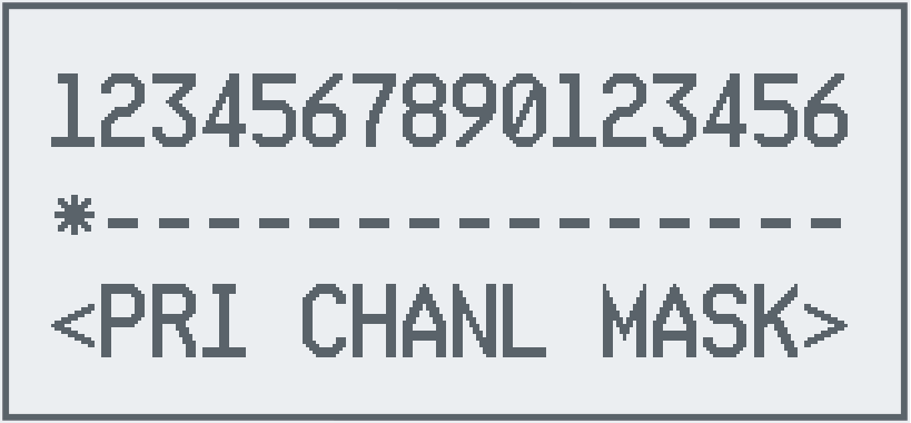
Figure 28. Primary Channel Mask Screen
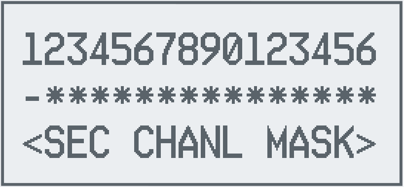
Figure 29. Secondary Channel Mask Screen
| <Primary Channel Mask>, <Secondary Channel Mask> Screens – view mode | ||
|---|---|---|
| Key | Functionality | Comment |
| a/d | Menu navigation | Move to previous/next screen |
| e | Select | Enter edit mode |
| <Primary Channel Mask>, <Secondary Channel Mask> Screens – edit mode | ||
|---|---|---|
| Key | Functionality | Comment |
| a/d | Channel navigation | Move to previous/next channel indicator |
| w/s | Value change | Increase/decrease the value of the highlighted digit |
| e | Select | Save and exit mode |
<PAN ID> Screen
The PAN ID Screen (Figure 30.) allows changing of the default PAN ID (0xFFFF by default) to any desired value.
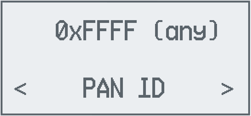
Figure 30. PAN ID Screen - view mode
| <PAN ID> Screen – view mode | ||
|---|---|---|
| Key | Functionality | Comment |
| a/d | Menu navigation | Move to previous/next screen |
| e | Select | Enter edit mode |
| <PAN ID> Screen – edit mode | ||
|---|---|---|
| Key | Functionality | Comment |
| a/d | Digit navigation | Move to previous/next digit |
| w/s | Value change | Increase/decrease the value of the highlighted digit |
| e | Select | Save and exit mode |
Base Device Behavior Commissioning Mode Screens
The Base Device Behavior (BDB) Commissioning Screens (Figure 34., Figure 35., Figure 36., Figure 37.) allow enabling/disabling of the top level commissioning procedures that will be performed when BDB commissioning is triggered by commissioning screen (Figure 38.) or any other means.
Touchlink
BDB Touchlink is a proximity commissioning method for network formation with
distributed security, this means that the network created does not have a Trust Center.
This procedure can be invoked on Router and End Devices, but not by Coordinators.
The commissioning involves two configurations which are Touchlink Initiator and
Touchlink Target. If the device supports Touchlink as Target (by setting the compile
option BDB_TL_TARGET), the screen Figure 31. in the commissioning
menu allows you the amount of time the device
will accept the touchlink commissioning process, while the screen
Figure 32. sets the allow stealing configuration.
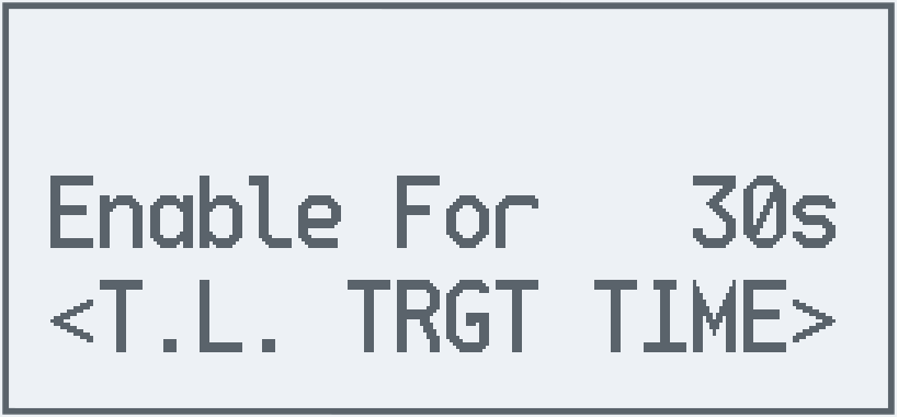
Figure 31. Touchlink Target time screen
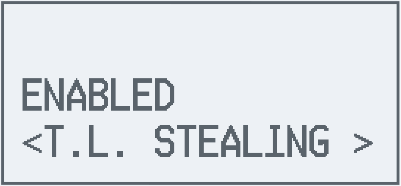
Figure 32. Touchlink Target allow stealing screen
Touchlink as target is not executed when commissioning screen is triggered, instead it has its own menu Figure 33. from which is triggered which when enabled shows the remaining time in which the commissioning process can be performed.
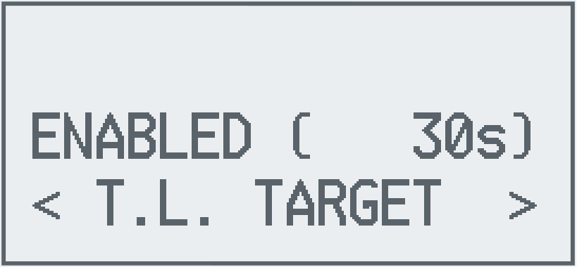
Figure 33. Touchlink Target enabled time screen
If the device supports Touchlink as Initiator (by setting the compile option
BDB_TL_INITIATOR), the screen Figure 31. in the commissioning menu
allows you to set if Touchlink as initiator will be executed when commissioning screen is triggered.
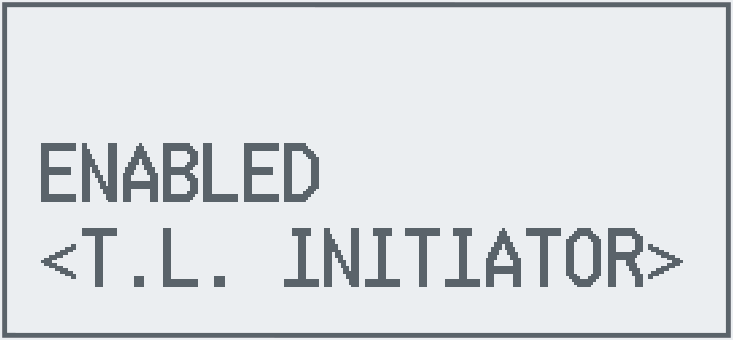
Figure 34. Touchlink Initiator Screen
More details on this commissioning process are provided in section 12 of Z-Stack Overview.
Formation
BDB Formation procedure is meant to be used by Coordinator devices and Router devices. Coordinator devices will create a centralized network, whereas Router devices will create a distributed network, after which any other Router or End Device may join these networks. For further details on the differences between these two types of networks please refer to section 10 of Z-Stack Overview. This commissioning procedure cannot be used if the device is already on a network or do not have formation capabilities such as End Devices.
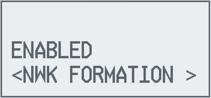
Figure 35. Formation Screen
Network Steering
BDB Network Steering procedure is meant to allow joining devices such as Router and End Devices perform the discovery of the networks and join any suitable network, performing the network discovery process necessary to complete the joining. Devices that are already in a network will use this commissioning procedure to open the network and allow other devices join the network.
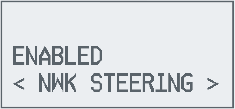
Figure 36. Steering Screen
Finding and Binding
BDB Finding and Binding is an application commissioning procedure that allows applications to match the clusters with other devices so it can easily perform binds. For example, Light devices will set Identify mode state for 180 seconds, in which it can be discovered by Switch devices performing this commissioning procedure. After the Switch device create the binds with the Light devices found during the procedure it will be able to control those lights.
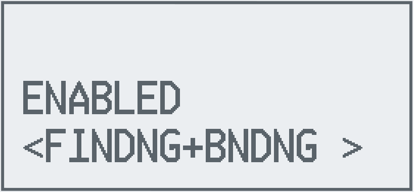
Figure 37. Finding and Binding Screen
| <T.L. Initiator >,<Nwk Formation>, <Nwk Steering>, <Findng+Bndng> Screens | ||
|---|---|---|
| Key | Functionality | Comment |
| a/d | Menu navigation | Move to previous/next screen |
| e | Select | Toggle enable/disable commissioning procedure |
<Commissioning> Screen
The Commissioning Screen (Figure 38.) starts the BDB top level commissioning process selected in the configuration menus.
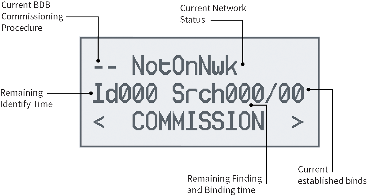
Figure 38. Commissioning Screen
The current BDB Commissioning Procedure being executed is shown in the upper right corner of the LCD as follows:
- NS - Network Steering.
- NF - Network Formation.
- FB - Finding and Binding.
- PL - Parent Lost (for end devices only).
- – - idle (commissioning not currently active).
The current Network status is displayed as follows:
- NotOnNwk - not currently connected to a network.
- FORM - network was formed by the current device during the latest execution of the NF method.
- JOIN - the current device joined an existing network during the latest execution of the NS method.
- EXST - the device was already connected to a network when the commissioning was started.
Joining permission state (not shown on end devices):
- CLOSED - the current device is closed for joining of other devices.
- OpenXXX - the current device is open for joining of other devices, and will close in XXX seconds.
| <Commission> Screen | ||
|---|---|---|
| Key | Functionality | Comment |
| a/d | Menu navigation | Move to previous/next screen |
| e | Select | Start commissioning procedure |
<Reset to FN> Screen
Reset to Factory New (Figure 39.) clears the devices network information and restores the NVM tables to default. The device will perform a soft reset automatically during this procedure and then display the Welcome Screen (Figure 20.).
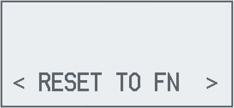
Figure 39. Reset to Factory New Screen
| <Reset to Fn> Screen | ||
|---|---|---|
| Key | Functionality | Comment |
| a/d | Menu navigation | Move to previous/next screen |
| e | Select | Perform Factory New Reset |
Note
Due to the LaunchPad’s XDS110 emulator device control during programming, the device must undergo a hardware reset (typically via a push button pull-down on the RESET pin or power cycle) in order for this screen to effectively perform a software reset instead of crashing
<Back> Screen
The Back Screen (Figure 40.) allows returning to the previous screen. When the back action is performed the upper level screen will be displayed automatically.

Figure 40. Back Screen
| <Back> Screen | ||
|---|---|---|
| Key | Functionality | Comment |
| a/d | Menu navigation | Move to previous/next screen |
| e | Select | Back to upper menu |
<Green Power Proxy Commissioning> Screen
The Green Power Proxy Commissioning Screen shows whether the GP Proxy device is being commissioned or not by a Green Power Sink device. If the commissioning process is not in progress it will show as “DISABLED”, if the commissioning process is in progress but does not have a timeout it will show as “ENABLED”, if the commissioning process has timeout it will be displayed as TIME XXX, where XXX is the remaining time in seconds.

| <Green Power Proxy Commissioning> Screen | ||
|---|---|---|
| Key | Functionality | Comment |
| a/d | Menu navigation | Move to previous/next screen |
<App> Menu
The App menu (Figure 41.) is application specific and will contain the menus to interact with the specific application implementation. Those specific application menus are explained in the README documentation provided by each application and referred in Running the Example Applications.
This menu is intented to be used once the device is already commissioned to a network, as it provides ways to interact with the other devices in the network. For example, Switch application will have a Toggle Remote Light interface which will trigger the Switch application to send a Toggle Light command to all lights previously binded.

Figure 41. App Screen
| <App> Menu | ||
|---|---|---|
| Key | Functionality | Comment |
| a/d | Menu navigation | Move to previous/next screen |
| e | Select | Back to upper menu |