Zigbee Configuration
These instructions cover all Z-Stack sample applications. Configurables differ between standard Zigbee device types (ie. Coordinator, Router, End Device) and Green Power Devices (GPD).
Note
SysConfig will only make changes to selected files, listed in the Generated Files view. Any required changes to your application files must be done on your own.
Open An Example Project
Open the stand-alone SysConfig tool or import a SysConfig-enabled example project
(found in the {SDK_INSTALL_DIR}/examples/syscfg_preview folder) and open the
.syscfg file with the System Configuration Editor.
Zigbee Settings
In the RF STACKS → Z-Stack view, you can configure Zigbee stack parameters.
Parameters are explained in the tooltip that appears when you hover over it but
further explanations are provided in the Z-Stack Overview and
4. Migrate Configuration Header File sections.
Zigbee stack settings are stored in default/sysconfig/ti_zstack_config.h (which appears after building the project).
Here is an example of what you would see for a coordinator example:
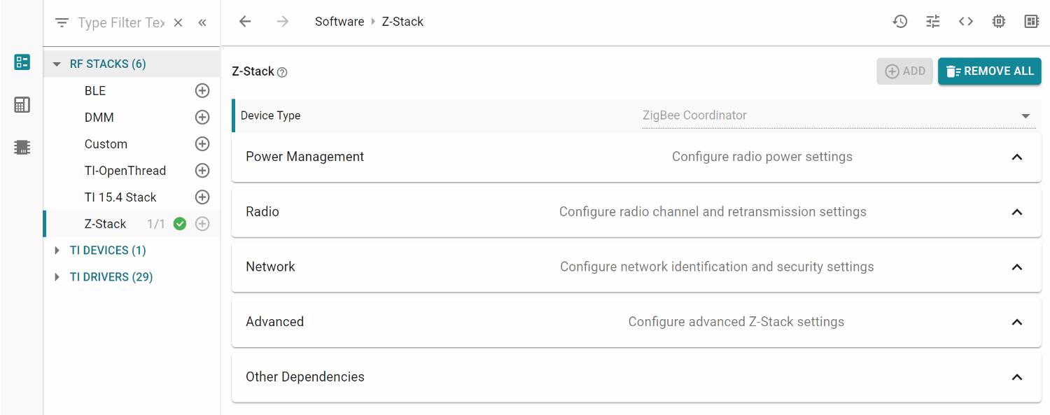
Device Type and Power Management Configuration
Standard Zigbee Device
The Device Type (Coordinator, Router, End Device) is pre-determined for each example project and cannot be changed. The Power Mode of Operation (see End Device), poll period (see Child Management), and specific poll rates (Portable Devices) are only configurable for End Device projects.
Green Power Device
The device type is Green Power Device. The Power Mode of Operation determines whether the Green Power Device is assumed to have a constant power source (eg. battery) or not. For more details, see BATTERYLESS_DEVICE in Green Power Device Configuration.
Radio Configuration
Standard Zigbee Device
The basic Radio parameters to consider for the Zigbee stack include primary and secondary channel mask selection (Configuring Channel) as well as minimum transmissions (Network Manager). This is also where the power output can be selected and the internal Power Amplifier (PA) can be enabled if applicable (Power Configuration).
Green Power Device
Configure the channel which the GPD will operate on.
Network Configuration
Standard Zigbee Device
The network configurations involve basic Zigbee network settings, such as the PAN ID (Configuring the PAN ID and Network to Join), extended PAN ID (Extended PAN IDs), default network and TC link keys (Security), and link status jitter mask (Asynchronous Links). Joining devices can also select the distributed global link key (Distributed Security Network) whereas routing devices have a maximum device list option (Network Configurations). Coordinators can also determine the maximum number of TCLK entries stored (For Trust Center (TC) Devices).
Green Power Device
Green Power Device Type determines what function the GPD embodies in the network (eg. switch, temperature sensor, etc). Green Power Device ID Type determines how the GPD identifies itself (eg. Configurable GPD ID, IEEE address). If Configurable GPD ID is selected, the developer may choose a 32-bit ID which the GPD will use.
Security Configuration
Green Power Device
Security settings which are specific towards Green Power devices, such as level and key type, and key, which are further discussed in Green Power Device Configuration.
Advanced Configuration
Standard Zigbee Device
The advanced configuration parameters require in-depth knowledge of the Zigbee network operation. They are separated into different sections for joining (Miscellaneous), routing (Routing Protocol), packet sending (End-to-End Acknowledgements), and maximum table sizes (Network Address Assignment). Several of these settings are also explained in Network Configurations.
Green Power Device
Data Frame Retries determines how many times the GPD will transmit each packet. Auto-commissioning determines whether the GPD will set the auto-commissioning bit in the packets. Radio Receive After Transmit determines whether the GPD should expect to receive a packet after transmitting. Sequence Number Capability determines whether the GPD will use sequential MAC sequence numbers.
Adjust Your Application
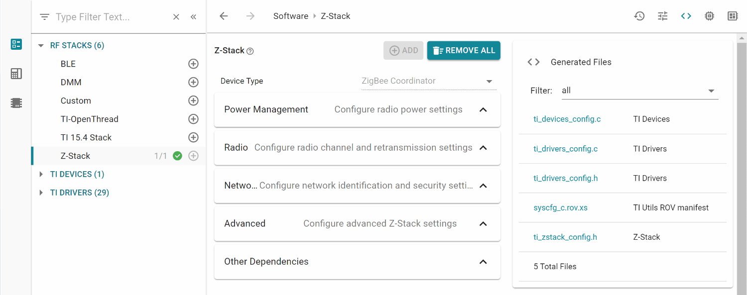
When you have finished adjusting the parameters, save the .syscfg file.
You can preview the files which will be generated by clicking the <> symbol. In this example,
ti_devices_config.c, ti_drivers_config.c/h, and ti_zstack_config.h were generated respectively by the TI DEVICES, TI DRIVERS, and RF STACKS → Z-Stack views.
If you are using the System Configuration stand-alone tool, you will have to
import every generated file to your IDE. For the SysConfig CCS plug-in,
you can generate all the files by building your project. After the build has
completed, you will find the generated files in the output folder of your project,
called default/syscfg. All parameters configured in the Zigbee view of
SysConfig will result in a #define in ti_zstack_config.h alongside other macros
which are not included in SysConfig.
Attention
Whenever you re-build the project, SysConfig will re-generate the files.
Because of this, any changes made directly to ti_zstack_config.h will be overwritten.