

|
|
SPI driver implementation for a CC26XX SPI controller using the UDMA controller.
The SPI header file should be included in an application as follows:
Refer to SPI.h for a complete description of APIs.
Note that the user also needs to include the UDMACC26XX.h driver since the SPI uses uDMA in order to improve throughput.
The general SPI API should be used in application code, i.e. SPI_open() should be used instead of SPICC26XXDMA_open(). The board file will define the device specific config, and casting in the general API will ensure that the correct device specific functions are called. This is also reflected in the example code in Use Cases.
Before using SPI on CC26XX:
The following is true for slave operation:
The following apply for master operation:
After SPI operation has ended:
The callback function is called in the following context:
If an RX overrun occurs during slave operation:
Timeout can occur in SPI_MODE_BLOCKING, there's no timeout in SPI_MODE_CALLBACK. When in SPI_MODE_CALLBACK, the transfer must be cancelled by calling SPI_transferCancel().
If a timeout happens in either SPI_SLAVE or SPI_MASTER mode, the receive buffer will contain the bytes received up until the timeout occurred. The SPI transaction status will be set to SPI_TRANSFER_FAILED. The SPI transaction count will be set to the number of bytes sent/received before timeout. The remaining bytes will be flushed from the TX FIFO so that the subsequent transfer can be executed correctly. Note that specifying a timeout prevents the driver from performing a polling transfer when in slave mode.
The TI-RTOS power management framework will try to put the device into the most power efficient mode whenever possible. Please see the technical reference manual for further details on each power mode.
The SPICC26XXDMA.h driver is setting a power constraint during transfers to keep the device out of standby. When the transfer has finished, the power constraint is released. The following statements are valid:
This SPI controller supports a hardware chip select pin. Refer to the user manual on how this hardware chip select pin behaves in regards to the SPI frame format.
| Chip select type | SPI_MASTER mode | SPI_SLAVE mode |
|---|---|---|
| Hardware chip select | No action is needed by the application to select the peripheral. | See the device documentation on it's chip select requirements. |
| Software chip select | The application is responsible to ensure that correct SPI slave is selected before performing a SPI_transfer(). | See the device documentation on it's chip select requirements. |
In a scenario where the SPI module is operating in master mode with multiple SPI slaves, the chip select pin can be reallocated at runtime to select the appropriate slave device. See Master Mode With Multiple Slaves use case below. This is only relevant when chip select is a hardware chip select. Otherwise the application can control the chip select pins directly using the PIN driver.
SPI data frames can be any size from 4-bits to 16-bits. If the dataSize in SPI_Params is greater that 8-bits, then the SPICC26XXDMA driver implementation will assume that the SPI_Transaction txBuf and rxBuf point to an array of 16-bit uint16_t elements.
| dataSize | buffer element size |
|---|---|
| 4-8 bits | uint8_t |
| 9-16 bits | uint16_t |
When the SPI is configured as SPI slave, the maximum bit rate is 4MHz.
When the SPI is configured as SPI master, the maximum bit rate is 12MHz.
The UDMA module generates IRQs on the SPI interrupt vector. This driver automatically installs a UDMA aware Hwi (interrupt) to service the assigned UDMA channels.
The UDMA controller only supports data transfers of up to 1024 data frames. A transfer with more than 1024 frames will be transmitted/received in multiple 1024 sized portions until all data has been transmitted/received. A data frame can be 4 to 16 bits in length.
A uint16_t scratch buffer is used to allow SPI_transfers where txBuf or rxBuf are NULL. Rather than requiring txBuf or rxBuf to have a dummy buffer of size of the transfer count, a single-word UDMA accessible uint16_t scratch buffer is used. When rxBuf is NULL, the UDMA will transfer all the received SPI data into the scratch buffer as a "bit-bucket". When txBuf is NULL, the scratch buffer is initialized to defaultTxBufValue so the uDMA will send some known value. Each SPI driver instance uses its own scratch buffer.
Before SPI_transfer, txBuf should be filled with the outgoing SPI data. These data are sent out during the transfer, while the incoming data are received into rxBuf. To save memory space, txBuf and rxBuf can be assigned to the same buffer location. At the beginning of the transfer, this buffer holds outgoing data. At the end of the transfer, the outgoing data are overwritten and the buffer holds the received SPI data.
When used in blocking mode small SPI transfers are can be done by polling the peripheral & sending data frame-by-frame. A master device can perform the transfer immediately and return, but a slave will block until it receives the number of frames specified in the SPI_Transfer() call. The minDmaTransferSize field in the hardware attributes is the threshold; if the transaction count is below the threshold a polling transfer is performed; otherwise a DMA transfer is done. This is intended to reduce the overhead of setting up a DMA transfer to only send a few data frames.
Notes:
| Generic API function | API function | Description |
|---|---|---|
| SPI_init() | SPICC26XXDMA_init() | Initialize SPI driver |
| SPI_open() | SPICC26XXDMA_open() | Initialize SPI HW and set system dependencies |
| SPI_close() | SPICC26XXDMA_close() | Disable SPI and UDMA HW and release system dependencies |
| SPI_control() | SPICC26XXDMA_control() | Configure an already opened SPI handle |
| SPI_transfer() | SPICC26XXDMA_transfer() | Start transfer from SPI |
| SPI_transferCancel() | SPICC26XXDMA_transferCancel() | Cancel ongoing transfer from SPI |
The CC26XX SPI driver does not support:
Receive 100 bytes over SPI in SPI_MODE_BLOCKING.
This use case will perform a transfer in SPI_MODE_BLOCKING until the wanted amount of bytes is transferred or until chip select is deasserted by the SPI master. This SPI_transfer() call can be used when unknown amount of bytes shall be transferred. Note: The partial return is also possible in SPI_MODE_CALLBACK mode.
This use case will configure the SPI driver to transfer continuously in SPI_MODE_CALLBACK, 16 bytes at the time and echoing received data after every 16 bytes.
This use case will configure a SPI master to send the data in txBuf while receiving data to rxBuf in BLOCKING_MODE.
This use case will configure a SPI master to send data to one slave and then to another in BLOCKING_MODE. It is assumed that the board file is configured so that the two chip select pins have a default setting of a high output and that the SPICC26XXDMA_HWAttrsV1 used points to one of them since the SPI driver will revert to this default setting when switching the chip select pin.
External hardware connected on the SPI, i.e. SPI host/slave, might have configured a pull on one or more of the SPI lines. Dependent on the hardware, it might conflict with the pull used for the CC26XX SPI. To avoid increased leakage and ensure the lowest possible power consumption when the SPI is inactive, the application must configure a matching pull on the SPI IOs. An example of how this can be done is shown below.
To wake the SPI slave device up on deassertion of the chip select, the chip select pin must be controled outside of the SPI driver in between SPI transfers. The example below show how this can be implemented by registering the chip select pin with the PIN driver and configuring a callback on a falling edge. In the PIN callback, the chip select pin is released from the PIN driver, the SPI driver is opened, and a transaction started. During the SPI callback, the SPI driver is closed again and the chip select pin is reconfigured to trigger a callback on a falling edge again.
*Note: The SPI master must allow enough time between deasserting the chip select and the start of the transaction for the SPI slave to wake up and open up the SPI driver.
The SPI driver interface produces log statements if instrumentation is enabled.
| Diagnostics Mask | Log details |
|---|---|
| Diags_USER1 | basic SPI operations performed |
| Diags_USER2 | detailed SPI operations performed |
#include <stdint.h>#include <ti/drivers/SPI.h>#include <ti/drivers/pin/PINCC26XX.h>#include <ti/drivers/dma/UDMACC26XX.h>#include <ti/drivers/Power.h>#include <ti/drivers/power/PowerCC26XX.h>#include <ti/drivers/dpl/HwiP.h>#include <ti/drivers/dpl/SemaphoreP.h>#include <ti/drivers/dpl/SwiP.h>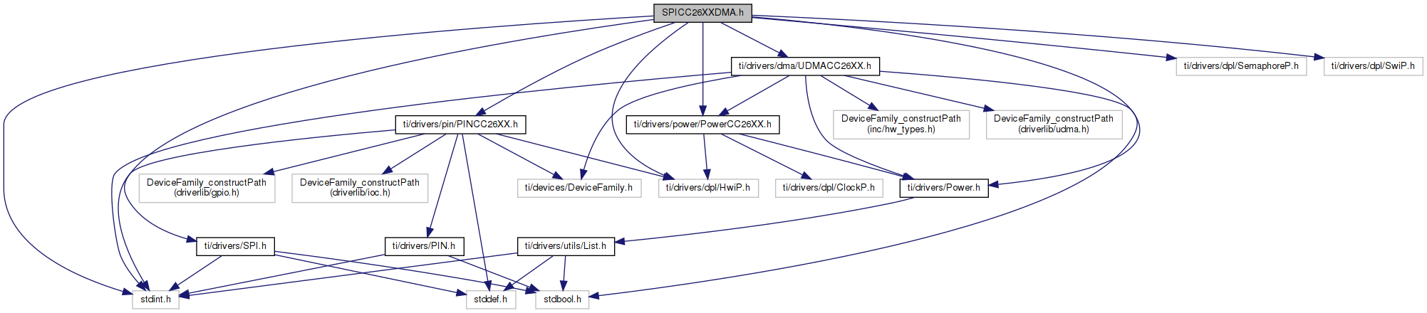
Go to the source code of this file.
Data Structures | |
| struct | SPICC26XXDMA_HWAttrsV1 |
| SPICC26XXDMA Hardware attributes. More... | |
| struct | SPICC26XXDMA_Object |
| SPICC26XXDMA Object. More... | |
Macros | |
| #define | SPICC26XXDMA_CMD_RETURN_PARTIAL_ENABLE (SPI_CMD_RESERVED + 0) |
| Command used by SPI_control to enable partial return. More... | |
| #define | SPICC26XXDMA_CMD_RETURN_PARTIAL_DISABLE (SPI_CMD_RESERVED + 1) |
| Command used by SPI_control to disable partial return. More... | |
| #define | SPICC26XXDMA_CMD_SET_CSN_PIN (SPI_CMD_RESERVED + 2) |
| Command used by SPI_control to re-configure chip select pin. More... | |
| #define | SPICC26XXDMA_RETURN_PARTIAL_ENABLE SPICC26XXDMA_CMD_RETURN_PARTIAL_ENABLE |
| #define | SPICC26XXDMA_RETURN_PARTIAL_DISABLE SPICC26XXDMA_CMD_RETURN_PARTIAL_DISABLE |
| #define | SPICC26XXDMA_SET_CSN_PIN SPICC26XXDMA_CMD_SET_CSN_PIN |
Typedefs | |
| typedef enum SPICC26XXDMA_FrameSize | SPICC26XXDMA_FrameSize |
| typedef struct SPICC26XXDMA_HWAttrsV1 | SPICC26XXDMA_HWAttrsV1 |
| SPICC26XXDMA Hardware attributes. More... | |
| typedef struct SPICC26XXDMA_Object | SPICC26XXDMA_Object |
| SPICC26XXDMA Object. More... | |
| typedef struct SPICC26XXDMA_Object * | SPICC26XXDMA_Handle |
Enumerations | |
| enum | SPICC26XXDMA_FrameSize { SPICC26XXDMA_8bit = 0, SPICC26XXDMA_16bit = 1 } |
Variables | |
| const SPI_FxnTable | SPICC26XXDMA_fxnTable |
| #define SPICC26XXDMA_RETURN_PARTIAL_ENABLE SPICC26XXDMA_CMD_RETURN_PARTIAL_ENABLE |
| #define SPICC26XXDMA_RETURN_PARTIAL_DISABLE SPICC26XXDMA_CMD_RETURN_PARTIAL_DISABLE |
| #define SPICC26XXDMA_SET_CSN_PIN SPICC26XXDMA_CMD_SET_CSN_PIN |
| typedef enum SPICC26XXDMA_FrameSize SPICC26XXDMA_FrameSize |
| typedef struct SPICC26XXDMA_HWAttrsV1 SPICC26XXDMA_HWAttrsV1 |
SPICC26XXDMA Hardware attributes.
These fields, with the exception of intPriority, are used by driverlib APIs and therefore must be populated by driverlib macro definitions. For CC26xxWare these definitions are found in:
intPriority is the SPI peripheral's interrupt priority, as defined by the underlying OS. It is passed unmodified to the underlying OS's interrupt handler creation code, so you need to refer to the OS documentation for usage. For example, for SYS/BIOS applications, refer to the ti.sysbios.family.arm.m3.Hwi documentation for SYS/BIOS usage of interrupt priorities. If the driver uses the ti.dpl interface instead of making OS calls directly, then the HwiP port handles the interrupt priority in an OS specific way. In the case of the SYS/BIOS port, intPriority is passed unmodified to Hwi_create().
A sample structure is shown below:
| typedef struct SPICC26XXDMA_Object SPICC26XXDMA_Object |
SPICC26XXDMA Object.
The application must not access any member variables of this structure!
| typedef struct SPICC26XXDMA_Object * SPICC26XXDMA_Handle |
| const SPI_FxnTable SPICC26XXDMA_fxnTable |