3.2.4.8. CPSW
3.2.4.8.1. Introduction
TI Common Platform Ethernet Switch (CPSW) is a three port switch (one CPU port and two external ports). The CPSW or Ethernet Switch driver follows the standard Linux network interface architecture.
The driver supports the following features:
- 10/100/1000 Mbps mode of operation.
- Auto negotiation.
- Linux NAPI support
- Switch Support
- VLAN (Subscription common for all ports)
- Ethertool (Supports only Slave 0 decided in cpsw DT node)
- Dual Standalone EMAC mode
Driver Configuration
To enable/disable Networking support, start the Linux Kernel Configuration tool:
$ make menuconfig
Select Device Drivers from the main menu.
...
...
Power management options --->
[*] Networking support --->
Device Drivers --->
File systems --->
Kernel hacking --->
...
...
Select Network device support as shown below:
...
...
[*] Multiple devices driver support (RAID and LVM)  --->
< > Generic Target Core Mod (TCM) and ConfigFS Infrastructure  ----
[*]Network device support --->
Input device support  --->
Character devices  --->
...
...
Select Ethernet driver support as shown below:
...
...
*** CAIF transport drivers ***
Distributed Switch Architecture drivers  --->
[*]   Ethernet driver support  --->
-*-   PHY Device support and infrastructure  --->
< >   Micrel KS8995MA 5-ports 10/100 managed Ethernet switch
< >   PPP (point-to-point protocol) support
...
...
Select ** as shown here:
...
[*]   Texas Instruments (TI) devices
< >     TI DaVinci EMAC Support
-*-     TI DaVinci MDIO Support
-*-     TI DaVinci CPDMA Support
-*-     TI CPSW Switch Phy sel Support
<*>     TI CPSW Switch Support
[ ]       TI Common Platform Time Sync (CPTS) Support
Module Build
Module build for the cpsw driver is supported. To do this, at all the places mentioned in the section above select module build (short-cut key M).
Select ** as shown here:
...
 [*]   Texas Instruments (TI) devices
 < >     TI DaVinci EMAC Support
 <M>     TI DaVinci MDIO Support
 <M>     TI DaVinci CPDMA Support
 -*-     TI CPSW Switch Phy sel Support
 <M>     TI CPSW Switch Support
 [ ]       TI Common Platform Time Sync (CPTS) Support
Interrupt Pacing
CPSW interrupt pacing feature limits the number of interrupts that occur during a given period of time. For heavily loaded systems in which interrupts can occur at a very high rate, the performance benefit is significant due to minimizing the overhead associated with servicing each interrupt.
To enable interrupt pacing, please execute below mentioned command using ethtool utility:
ethtool -C eth0 rx-usecs <delayperiod>
To achieve maximum performance set <delayperiod> to 500/250 depends on your platform
Configure number of TX/RX descriptors
By default CPSW allocates and uses as much CPPI Buffer Descriptors descriptors as can fit into the internal CPSW SRAM, which is usually is 256 descriptors. This is not enough for many high network throughput use-cases where packet loss rate should be minimized, so more RX/TX CPPI Buffer Descriptors need to be used.
CPSW allows to place and use CPPI Buffer Descriptors not only in SRAM, but also in DDR. The “descs_pool_size” module parameter can be used to setup total number of CPPI Buffer Descriptors to be allocated and used for both RX/TX path.
To configure descs_pool_size from kernel boot cmdline:
ti_cpsw.descs_pool_size=4096
To configure descs_pool_size from cmdline:
insmod ti_cpsw descs_pool_size=4096
Hence, the CPSW uses one pool of descriptors for both RX and TX which by default split between all channels proportionally depending on total number of CPDMA channels and number of TX and RX channels. Number of CPPI Buffer Descriptors allocated for RX and TX path can be customized via ethtool ‘-G’ command:
ethtool -G <devname> rx <number of descriptors>
ethtool ‘-G’ command will accept only number of RX entries and rest of descriptors will be arranged for TX automatically.
Defaults and limitations:
- minimum number of rx descriptors is max number of CPDMA channels (8)
  to be able to set at least one CPPI Buffer Descriptor per channel
- maximum number of rx descriptors is (descs_pool_size - max number of CPDMA channels (8))
- by default, descriptors will be split equally between RX/TX path
- any values passed in "tx" parameter will be ignored
Examples:
# ethtool -g eth0
       Pre-set maximums:
       RX:             7372
       RX Mini:        0
       RX Jumbo:       0
       TX:             0
       Current hardware settings:
       RX:             4096
       RX Mini:        0
       RX Jumbo:       0
       TX:             4096

# ethtool -G eth0 rx 7372
# ethtool -g eth0
       Ring parameters for eth0:
       Pre-set maximums:
       RX:             7372
       RX Mini:        0
       RX Jumbo:       0
       TX:             0
       Current hardware settings:
       RX:             7372
       RX Mini:        0
       RX Jumbo:       0
       TX:             820
VLAN Config
VLAN can be added/deleted using ip or vconfig utility. In switch mode
added vlan will be subscribed to all the ports, in Dual EMAC mode added
VLAN will be subscribed to host port and the respective slave ports.
VLAN Add
ip link add link eth0 name eth0.5 type vlan id 5

< or >

vconfig add eth0 5
VLAN del
ip link del eth0.5

< or >

vconfig rem eth0 5
IP assigning
IP address can be assigned to the VLAN interface either via udhcpc when a VLAN aware dhcp server is present or via static ip asigning using ip/ifconfig tools.
ip addr add 192.168.10.5/24 dev eth0.5
ip link set dev eth0 up

< or >

ifconfig eth0.5 192.168.10.5
Once VLAN is added, it will create a new entry in Ethernet interfaces like eth0.5, below is an example how it check the vlan interface
ip link show dev eth0.5
ip addr show dev eth0.5

< or >

ifconfig eth0.5
Packet Send/Receive
To Send or receive packets with the VLAN tag, bind the socket to the proper ethernet interface shown above and can send/receive via that socket-fd.
Multicast Add/Delete
Multicast MAC address can be added/deleted using the following ioctl commands SIOCADDMULTI and SIOCDELMULTI
Example
The following is the example to add and delete muliticast address 01:80:c2:00:00:0e
Add Multicast address
struct ifreq ifr;
ifr.ifr_hwaddr.sa_data[0] = 0x01;
ifr.ifr_hwaddr.sa_data[1] = 0x80;
ifr.ifr_hwaddr.sa_data[2] = 0xC2;
ifr.ifr_hwaddr.sa_data[3] = 0x00;
ifr.ifr_hwaddr.sa_data[4] = 0x00;
ifr.ifr_hwaddr.sa_data[5] = 0x0E;
ioctl(sockfd, SIOCADDMULTI, &ifr);
Delete Multicast address
struct ifreq ifr;
ifr.ifr_hwaddr.sa_data[0] = 0x01;
ifr.ifr_hwaddr.sa_data[1] = 0x80;
ifr.ifr_hwaddr.sa_data[2] = 0xC2;
ifr.ifr_hwaddr.sa_data[3] = 0x00;
ifr.ifr_hwaddr.sa_data[4] = 0x00;
ifr.ifr_hwaddr.sa_data[5] = 0x0E;
ioctl(sockfd, SIOCDELMULTI, &ifr);
Note
This interface does not support VLANs.
Dual Standalone EMAC mode
Introduction
This section provides the user guide for Dual Emac mode implementation. Following are the assumptions made for Dual Emac mode implementation
Block Diagram
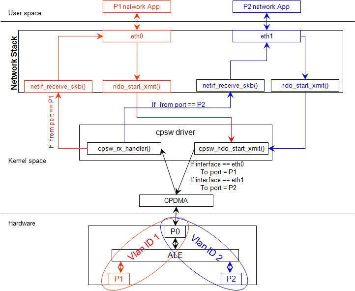
Assumptions
- Interrupt source is common for both eth interfaces
- CPDMA and skb buffers are common for both eth interfaces
- If eth0 is up, then eth0 napi is used. eth1 napi is used when eth0 interface is down
- CPSW and ALE will be in VLAN aware mode irrespective of enabling of 802.1Q module in Linux network stack for adding port VLAN.
- Interrupt pacing is common for both interfaces
- Hardware statistics is common for all the ports
- Switch config will not be available in dual emac interface mode
Constraints
The following are the constrains for Dual Emac mode implementation
- VLAN id 1 and 2 are reserved for EMAC 0 and 1 respectively for port segregation
- Port vlans mentioned in dts file are reserved and should not be added to cpsw through vconfig as it violate the Dual EMAC implementation and switch mode will be enabled.
- While adding VLAN id to the eth interfaces, same VLAN id should not be added in both interfaces which will lead to VLAN forwarding and act as switch
- Manual ip for eth1 is not supported from Linux kernel arguments
- Both the interfaces should not be connected to the same subnet unless only configuring bridging, and not doing IP routing, then you can configure the two interfaces on the same subnet.
Bridging Dual Emac interfaces
The Linux Bridge uses VLAN id 1 as default VLAN, by default. As result, the attempt to add Dual Emac interfaces to the Linux Bridge using default configuration may fail.
To allow Dual Emac interfaces to be added to the Linux Bridge one of following can be done:
or update DT “dual_emac_res_vlan” properties to avoid VID id 1 usage for Dual Emac mode
or reconfigure the Linux Bridge to not use VID id 1 as default VLAN:
ip link add name br0 type bridge
ip link set dev br0 type bridge vlan_filtering 0
echo "New VID id" > /sys/class/net/br0/bridge/default_pvid
ip link set dev br0 type bridge vlan_filtering 1
ip link set dev eth0 master br0
ip link set dev eth1 master br0
or configure the Linux Bridge in vlan unaware mode:
ip link add name br0 type bridge
ip link set dev br0 type bridge vlan_filtering 0
echo 0 > /sys/class/net/br0/bridge/default_pvid
ip link set dev eth0 master br0
ip link set dev eth1 master br0
Dual EMAC Device tree entry
Dual EMAC can be enabled with adding the entry dual_emac to the cpsw device tree node as the reference patch below
diff --git a/arch/arm/boot/dts/am335x-evmsk.dts b/arch/arm/boot/dts/am335x-evmsk.dts
index ac1f759..b50e9ef 100644
--- a/arch/arm/boot/dts/am335x-evmsk.dts
+++ b/arch/arm/boot/dts/am335x-evmsk.dts
@@ -473,6 +473,7 @@
        pinctrl-names = "default", "sleep";
        pinctrl-0 = <&cpsw_default>;
        pinctrl-1 = <&cpsw_sleep>;
+       dual_emac;
 };

 &davinci_mdio {
@@ -484,11 +485,13 @@
 &cpsw_emac0 {
        phy_id = <&davinci_mdio>, <0>;
        phy-mode = "rgmii-txid";
+       dual_emac_res_vlan = <1>;
 };

 &cpsw_emac1 {
        phy_id = <&davinci_mdio>, <1>;
        phy-mode = "rgmii-txid";
+       dual_emac_res_vlan = <2>;
 };
Bringing Up interfaces
Eth0 will be up by-default. Eth1 interface has to be brought up manually using either of the folloing command or through init scripts.
The network interface IP address can be configured automatically (DHCP) depending on root file system or configured manually. Manual configuration:
ip addr add 192.168.1.1/24 dev eth0
ip link set dev eth0 up

< or >

ifconfig eth0 <ip> netmask <mask> up
Primary Interface on Second External Port
There are some pin mux configurations on devices that use the CPSW 3P such as the AM335x, AM437x, AM57x and others that to enable Ethernet requires using the second external port as the primary interface. Here is a suggested DTS configuration when using the second port.
The key step is setting the active_slave flag to 1 in the MAC node of the board DTS, this tells the driver to use the second interface as primary in a single MAC configuration. The cpsw1 relates to the physical port and not the Ethernet device. Also make sure to remove the dual mac flag. This example configuration will still yield eth0 in the network interface list.
Please note this is an example for the AM335x, the PHY mode below will set tx internal delay (rgmii-txid) which is required for AM335x devices. Please consult example DTS files for the AM437x and AM57x EVMs for respective PHY modes.
&mac {
       pinctrl-names = "default", "sleep";
       pinctrl-0 = <&cpsw_default>;
       pinctrl-1 = <&cpsw_sleep>;
       active_slave = <1>;
       status = "okay";
};

&davinci_mdio {
       pinctrl-names = "default", "sleep";
       pinctrl-0 = <&davinci_mdio_default>;
       pinctrl-1 = <&davinci_mdio_sleep>;
       status = "okay";
};

&cpsw_emac1 {
       phy_id = <&davinci_mdio>, <1>;
       phy-mode = "rgmii-txid";
};
Switch Configuration Interface
Introduction
The CPSW Ethernet Switch can be configured in various different combination of Ethernet Packet forwarding and blocking. There is no such standard interface in Linux to configure a switch. This user guide provides an interface to configure the switch using Socket IOCTL through SIOCSWITCHCONFIG command.
Configuring Kernel with VLAN Support
Userspace binary formats —>
    Power management options  --->
[*] Networking support  --->
    Device Drivers  --->
    File systems  --->
    Kernel hacking  --->
--- Networking support
      Networking options  --->
[ ]   Amateur Radio support  --->
<*>   CAN bus subsystem support  --->
< >   IrDA (infrared) subsystem support  --->
< >   Bluetooth subsystem support  --->
< >   RxRPC session sockets
< > The RDS Protocol (EXPERIMENTAL)
< > The TIPC Protocol (EXPERIMENTAL)  --->
< > Asynchronous Transfer Mode (ATM)
< > Layer Two Tunneling Protocol (L2TP)  --->
< > 802.1d Ethernet Bridging
[ ] Distributed Switch Architecture support  --->
<*> 802.1Q VLAN Support
[*]   GVRP (GARP VLAN Registration Protocol) support
< > DECnet Support
< > ANSI/IEEE 802.2 LLC type 2 Support
< > The IPX protocol
Switch Config Commands
Following is sample code for configuring the switch.
#include <stdio.h>
...
#include <linux/net_switch_config.h>
int main(void)
{
    struct net_switch_config cmd_struct;
    struct ifreq ifr;
    int sockfd;
    strncpy(ifr.ifr_name, "eth0", IFNAMSIZ);
    ifr.ifr_data = (char*)&cmd_struct;
    if ((sockfd = socket(AF_INET, SOCK_DGRAM, 0)) < 0) {
        printf("Can't open the socket\n");
        return -1;
    }
    memset(&cmd_struct, 0, sizeof(struct net_switch_config));

    ...//initialise cmd_struct with switch commands

    if (ioctl(sockfd, SIOCSWITCHCONFIG, &ifr) < 0) {
        printf("Command failed\n");
        close(sockfd);
        return -1;
    }
    printf("command success\n");
    close(sockfd);
    return 0;
}
CONFIG_SWITCH_ADD_MULTICAST
CONFIG_SWITCH_ADD_MULTICAST is used to add a LLDP Multicast address and forward the multicast packet to the subscribed ports. If VLAN ID is greater than zero then VLAN LLDP/Multicast is added.
cmd_struct.cmd = CONFIG_SWITCH_ADD_MULTICAST
| Parameter | Description | Range |
|---|---|---|
| cmd_struct.addr | LLDP/Multicast Address | MAC Address |
| cmd_struct.port | Member port | Bit 0 – Host port/Port 0 | Bit 1 – Slave 0/Port 1 | Bit 2 – Slave 1/Port 2 | 0 – 7 |
| cmd_struct.vid | VLAN ID | 0 – 4095 |
| cmd_struct.super | Super | 0/1 |
Result
ioctl call returns success or failure.
CONFIG_SWITCH_DEL_MULTICAST
CONFIG_SWITCH_DEL_MULTICAST is used to Delete a LLDP/Multicast address with or without VLAN ID.
cmd_struct.cmd = CONFIG_SWITCH_DEL_MULTICAST
| Parameter | Description | Range |
|---|---|---|
| cmd_struct.addr | Unicast Address | MAC Address |
| cmd_struct.vid | VLAN ID | 0 – 4095 |
Result
ioctl call returns success or failure.
CONFIG_SWITCH_ADD_VLAN
CONFIG_SWITCH_ADD_VLAN is used to add VLAN ID.
cmd_struct.cmd = CONFIG_SWITCH_ADD_VLAN
| Parameter | Description | Range |
|---|---|---|
| cmd_struct.vid | VLAN ID | 0 – 4095 |
| cmd_struct.port | Member port | Bit 0 – Host port/Port 0 | Bit 1 – Slave 0/Port 1 | Bit 2 – Slave 1/Port 2 | 0 – 7 |
| cmd_struct.untag_port | Untagged Egress port mask | Bit 0 – Host port/Port 0 | Bit 1 – Slave 0/Port 1 | Bit 2 – Slave 1/Port 2 | 0 – 7 |
| cmd_struct.reg_multi | Registered Multicast flood port mask | Bit 0 – Host port/Port 0 | Bit 1 – Slave 0/Port 1 | Bit 2 – Slave 1/Port 2 | 0 – 7 |
| cmd_struct.unreg_multi | Unknown Multicast flood port mask | Bit 0 – Host port/Port 0 | Bit 1 – Slave 0/Port 1 | Bit 2 – Slave 1/Port 2 | 0 – 7 |
Result
ioctl call returns success or failure.
CONFIG_SWITCH_DEL_VLAN
CONFIG_SWITCH_DEL_VLAN is used to delete VLAN ID.
cmd_struct.cmd = CONFIG_SWITCH_DEL_VLAN
| Parameter | Description | Range |
|---|---|---|
| cmd_struct.vid | VLAN ID | 0 – 4095 |
Result
ioctl call returns success or failure.
CONFIG_SWITCH_ADD_UNKNOWN_VLAN_INFO
CONFIG_SWITCH_ADD_UNKNOWN_VLAN_INFO is used to set unknown VLAN Info.
cmd_struct.cmd = CONFIG_SWITCH_ADD_UNKNOWN_VLAN_INFO
| Parameter | Description | Range |
|---|---|---|
| cmd_struct.unknown_vla n_member | Port mask | Bit 0 – Host port/Port 0 | Bit 1 – Slave 0/Port 1 | Bit 2 – Slave 1/Port 2 | 0 - 7 |
| cmd_struct.unknown_vla n_reg_multi | Registered Multicast flood port mask | Bit 0 – Host port/Port 0 | Bit 1 – Slave 0/Port 1 | Bit 2 – Slave 1/Port 2 | 0 - 7 |
| cmd_struct.unknown_vla n_unreg_multi | Unknown Multicast flood port mask | Bit 0 – Host port/Port 0 | Bit 1 – Slave 0/Port 1 | Bit 2 – Slave 1/Port 2 | 0 - 7 |
| cmd_struct.unknown_vla n_untag | Unknown Vlan Member port mask | Bit 0 – Host port/Port 0 | Bit 1 – Slave 0/Port 1 | Bit 2 – Slave 1/Port 2 | 0 - 7 |
Result
ioctl call returns success or failure.
CONFIG_SWITCH_SET_PORT_CONFIG
CONFIG_SWITCH_SET_PORT_CONFIG is used to set Phy Config.
cmd_struct.cmd = CONFIG_SWITCH_SET_PORT_CONFIG
| Parameter | Description | Range |
|---|---|---|
| cmd_struct.port | Port number | 0 - 2 |
| cmd_struct.ecmd | Phy settings | Fill this structure (struct ethtool_cmd), refer file include/uapi/linux/ethtool.h |
Result
ioctl call returns success or failure.
CONFIG_SWITCH_GET_PORT_CONFIG
CONFIG_SWITCH_GET_PORT_CONFIG is used to get Phy Config.
cmd_struct.cmd = CONFIG_SWITCH_GET_PORT_CONFIG
| Parameter | Description | Range |
|---|---|---|
| cmd_struct.port | Port number | 0 - 2 |
Result
ioctl call returns success or failure.
On success “cmd_struct.ecmd” holds port phy settings
CONFIG_SWITCH_SET_PORT_STATE
CONFIG_SWITCH_SET_PORT_STATE is used to set port status.
cmd_struct.cmd = CONFIG_SWITCH_SET_PORT_STATE
| Parameter | Description | Range |
|---|---|---|
| cmd_struct.port | Port number | 0 - 2 |
| cmd_struct.port_state | Port state | PORT_STATE_DISABLED/ PORT_STATE_BLOCKED/ PORT_STATE_LEARN/ PORT_STATE_FORWARD |
Result
ioctl call returns success or failure.
CONFIG_SWITCH_GET_PORT_STATE
CONFIG_SWITCH_GET_PORT_STATE is used to set port status.
cmd_struct.cmd = CONFIG_SWITCH_GET_PORT_STATE
| Parameter | Description | Range |
|---|---|---|
| cmd_struct.port | Port number | 0 - 2 |
Result
ioctl call returns success or failure.
On success “cmd_struct.port_state” holds port state
CONFIG_SWITCH_RATELIMIT
CONFIG_SWITCH_RATELIMIT is used to enable/disable rate limit of the ports.
The MC/BC Rate limit feature filters of BC/MC packets per sec as following:
number_of_packets/sec = (Fclk / ALE_PRESCALE) * port.BCAST/MCAST_LIMIT
where: ALE_PRESCALE width is 19bit and min value 0x10.
Each ALE prescale pulse loads port.BCAST/MCAST_LIMIT into the port MC/BC rate limit counter and port counters are decremented with each packet received or transmitted depending on whether the mode is transmit or receive. ALE prescale pulse frequency detrmined by ALE_PRESCALE register.
with Fclk = 125MHz and port.BCAST/MCAST_LIMIT = 1
max number_of_packets/sec = (125MHz / 0x10) * 1 = 7 812 500
min number_of_packets/sec = (125MHz / 0xFFFFF) * 1 = 119
So port.BCAST/MCAST_LIMIT can be selected to be 1 while ALE_PRESCALE is calculated as:
ALE_PRESCALE = Fclk / number_of_packets
cmd\_struct.cmd = CONFIG\_SWITCH\_RATELIMIT
| Parameter | Description | Range |
|---|---|---|
| cmd_struct.direction | Transmit/Receive | Transmit - 1 Receive - 0 |
| cmd_struct.port | Port number | 0 - 2 |
| cmd_struct.bcast_rate_limit | Broadcast, No of Packet | number_of_packets/sec |
| cmd_struct.mcast_rate_limit | Multicast, No of Packet | number_of_packets/sec |
Result
ioctl call returns success or failure.
Switch config ioctl mapping with v3.2
This section is applicable only to whom are migrating from v3.2 to v3.14 for am335x.
| v3.2 ioctl | Method in v3.14 | Comments |
|---|---|---|
| CONFIG_SWITCH_ADD_MULTICAST | CONFIG_SWITCH_ADD_MULTICAST | |
| CONFIG_SWITCH_ADD_UNICAST | Deprecated | Not supported as switch can learn by ingress packet |
| CONFIG_SWITCH_ADD_OUI | Deprecated | |
| CONFIG_SWITCH_FIND_ADDR | Deprecated | Address can be searched via ethtool -d ethX or switch-config -d,--dump |
| CONFIG_SWITCH_DEL_MULTICAST | CONFIG_SWITCH_DEL_MULTICAST | |
| CONFIG_SWITCH_DEL_UNICAST | Deprecated | |
| CONFIG_SWITCH_ADD_VLAN | CONFIG_SWITCH_ADD_VLAN | |
| CONFIG_SWITCH_FIND_VLAN | Deprecated | Address can be searched via ethtool -d ethX or switch-config -d,--dump |
| CONFIG_SWITCH_DEL_VLAN | CONFIG_SWITCH_DEL_VLAN | |
| CONFIG_SWITCH_SET_PORT_VLAN_CONFIG | CONFIG_SWITCH_SET_PORT_VLAN_CONFIG | |
| CONFIG_SWITCH_TIMEOUT | Deprecated | There is no hardware timers, a software timer of 10S is used to clear untouched entries in ALE table. |
| CONFIG_SWITCH_DUMP | Deprecated | Address can be searched via ethtool -d ethX or switch-config -d,--dump |
| CONFIG_SWITCH_SET_FLOW_CONTROL | Deprecated | Address can be searched via ethtool -A ethX <parameters> |
| CONFIG_SWITCH_SET_PRIORITY_MAPPING | Deprecated | |
| CONFIG_SWITCH_PORT_STATISTICS_ENABLE | Deprecated | statistics is enabled for all ports by default |
| CONFIG_SWITCH_CONFIG_DUMP | Deprecated | Address can be searched via ethtool -S ethX |
| CONFIG_SWITCH_RATELIMIT | CONFIG_SWITCH_RATELIMIT | |
| CONFIG_SWITCH_VID_INGRESS_CHECK | Deprecated | |
| CONFIG_SWITCH_ADD_UNKNOWN_VLAN_INFO | CONFIG_SWITCH_ADD_UNKNOWN_VLAN_INFO | |
| CONFIG_SWITCH_802_1 | Deprecated | Can be achecived by adding respective multicast address using CONFIG_SWITCH_ADD_MULTICAST |
| CONFIG_SWITCH_MACAUTH | Deprecated | |
| CONFIG_SWITCH_SET_PORT_CONFIG | CONFIG_SWITCH_SET_PORT_CONFIG | |
| CONFIG_SWITCH_GET_PORT_CONFIG | CONFIG_SWITCH_GET_PORT_CONFIG | |
| CONFIG_SWITCH_PORT_STATE | CONFIG_SWITCH_GET_PORT_STATE/ CONFIG_SWITCH_SET_PORT_STATE | |
| CONFIG_SWITCH_RESET | Deprecated | Close the interface and open the interface again which will reset the switch by default. |
ethtool - Display or change ethernet card settings
ethtool DEVNAME Display standard information about device
# ethtool eth0
Settings for eth0:
Supported ports: [ TP MII ]
Supported link modes:   10baseT/Half 10baseT/Full
                        100baseT/Half 100baseT/Full
                        1000baseT/Half 1000baseT/Full
Supported pause frame use: Symmetric
Supports auto-negotiation: Yes
Advertised link modes:  10baseT/Half 10baseT/Full
                        100baseT/Half 100baseT/Full
                        1000baseT/Half 1000baseT/Full
Advertised pause frame use: Symmetric
Advertised auto-negotiation: Yes
Link partner advertised link modes:  10baseT/Half 10baseT/Full
                                     100baseT/Half 100baseT/Full
                                     1000baseT/Full
Link partner advertised pause frame use: Symmetric
Link partner advertised auto-negotiation: Yes
Speed: 1000Mb/s
Duplex: Full
Port: MII
PHYAD: 1
Transceiver: external
Auto-negotiation: on
Supports Wake-on: d
Wake-on: d
Current message level: 0x00000000 (0)
Link detected: yes"
ethtool -i|–driver DEVNAME Show driver information
#ethtool -i eth0
driver: cpsw
version: 1.0
firmware-version:
expansion-rom-version:
bus-info: 48484000.ethernet
supports-statistics: yes
supports-test: no
supports-eeprom-access: no
supports-register-dump: yes
supports-priv-flags: no"
ethtool -P|–show-permaddr DEVNAME Show permanent hardware address
# ethtool -P eth0
Permanent address: a0:f6:fd:a6:46:6e"
ethtool -s|–change DEVNAME Change generic options
Below commands will be redirected to the phy driver:
[ speed %d ]
[ duplex half|full ]
[ autoneg on|off ]
[ wol p|u|m|b|a|g|s|d... ]
[ sopass %x:%x:%x:%x:%x:%x ]
Note
CPSW driver do not perform any kind of WOL specific actions or configurations.
#ethtool -s eth0 duplex half speed 100
[ 3550.892112] cpsw 48484000.ethernet eth0: Link is Down
[ 3556.088704] cpsw 48484000.ethernet eth0: Link is Up - 100Mbps/Half - flow control off
Sets the driver message type flags by name or number
[ msglvl %d | msglvl type on|off ... ]
# ethtool -s eth0 msglvl drv off
# ethtool -s eth0 msglvl ifdown off
# ethtool -s eth0 msglvl ifup off
# ethtool eth0
Current message level: 0x00000031 (49)
                       drv ifdown ifup
ethtool -r|–negotiate DEVNAME Restart N-WAY negotiation
# ethtool -r eth0
[ 4338.167685] cpsw 48484000.ethernet eth0: Link is Down
[ 4341.288695] cpsw 48484000.ethernet eth0: Link is Up - 1Gbps/Full - flow control rx/tx"
ethtool -a|–show-pause DEVNAME Show pause options
# ethtool -a eth0
Pause parameters for eth0:
Autonegotiate:  off
RX:             off
TX:             off
ethtool -A|–pause DEVNAME Set pause options
# ethtool -A eth0 rx on tx on
cpsw 48484000.ethernet eth0: Link is Up - 1Gbps/Full - flow control rx/tx
# ethtool -a eth0
Pause parameters for eth0:
Autonegotiate:  off
RX:             on
TX:             on
ethtool -C|–coalesce DEVNAME Set coalesce options
[rx-usecs N]
See [“Interrupt Pacing”] section for more information”
# ethtool -C eth0 rx-usecs 500
ethtool -c|–show-coalesce DEVNAME Show coalesce options
# ethtool -c eth0
Coalesce parameters for eth0:
Adaptive RX: off  TX: off
stats-block-usecs: 0
sample-interval: 0
pkt-rate-low: 0
pkt-rate-high: 0
rx-usecs: 0
rx-frames: 0
rx-usecs-irq: 0
rx-frames-irq: 0
tx-usecs: 0
tx-frames: 0
tx-usecs-irq: 0
tx-frames-irq: 0
rx-usecs-low: 0
rx-frame-low: 0
tx-usecs-low: 0
tx-frame-low: 0
rx-usecs-high: 0
rx-frame-high: 0
tx-usecs-high: 0
Tx-frame-high: 0
ethtool -G|–set-ring DEVNAME Set RX/TX ring parameters
Supported options:
[ rx N ]
See [“Configure number of TX/RX descriptors”] section for more information
# ethtool -G eth0 rx 8000
ethtool -g|–show-ring DEVNAME Query RX/TX ring parameters
# ethtool -g eth0
Ring parameters for eth0:
Pre-set maximums:
RX:             8184
RX Mini:        0
RX Jumbo:       0
TX:             0
Current hardware settings:
RX:             8000
RX Mini:        0
RX Jumbo:       0
TX:             192
ethtool -d|–register-dump DEVNAME Do a register dump
This command will dump current ALE table
# ethtool -d eth0
Offset          Values
------          ------
0x0000:         00 00 00 00 00 00 02 20 05 00 05 05 14 00 00 00
0x0010:         ff ff 02 30 ff ff ff ff 01 00 00 00 da 74 02 30
0x0020:         b9 83 48 ea 00 00 00 00 00 00 00 20 07 00 00 07
0x0030:         14 00 00 00 00 01 02 30 01 00 00 5e 0c 00 00 00
0x0040:         33 33 01 30 01 00 00 00 00 00 00 00 00 00 01 20
0x0050:         03 00 03 03 0c 00 00 00 ff ff 01 30 ff ff ff ff
ethtool -S|–statistics DEVNAME Show adapter statistics
# ethtool -S eth0
NIC statistics:
   Good Rx Frames: 24
   Broadcast Rx Frames: 12
   Multicast Rx Frames: 4
   Pause Rx Frames: 0
   Rx CRC Errors: 0
   Rx Align/Code Errors: 0
   Oversize Rx Frames: 0
   Rx Jabbers: 0
   Undersize (Short) Rx Frames: 0
   Rx Fragments: 1
   Rx Octets: 4290
   Good Tx Frames: 379
   Broadcast Tx Frames: 144
   Multicast Tx Frames: 228
   Pause Tx Frames: 0
   Deferred Tx Frames: 0
   Collisions: 0
   Single Collision Tx Frames: 0
   Multiple Collision Tx Frames: 0
   Excessive Collisions: 0
   Late Collisions: 0
   Tx Underrun: 0
   Carrier Sense Errors: 0
   Tx Octets: 72498
   Rx + Tx 64 Octet Frames: 30
   Rx + Tx 65-127 Octet Frames: 218
   Rx + Tx 128-255 Octet Frames: 0
   Rx + Tx 256-511 Octet Frames: 155
   Rx + Tx 512-1023 Octet Frames: 0
   Rx + Tx 1024-Up Octet Frames: 0
   Net Octets: 76792
   Rx Start of Frame Overruns: 0
   Rx Middle of Frame Overruns: 0
   Rx DMA Overruns: 0
   Rx DMA chan 0: head_enqueue: 2
   Rx DMA chan 0: tail_enqueue: 12114
   Rx DMA chan 0: pad_enqueue: 0
   Rx DMA chan 0: misqueued: 0
   Rx DMA chan 0: desc_alloc_fail: 0
   Rx DMA chan 0: pad_alloc_fail: 0
   Rx DMA chan 0: runt_receive_buf: 0
   Rx DMA chan 0: runt_transmit_bu: 0
   Rx DMA chan 0: empty_dequeue: 0
   Rx DMA chan 0: busy_dequeue: 14
   Rx DMA chan 0: good_dequeue: 21
   Rx DMA chan 0: requeue: 1
   Rx DMA chan 0: teardown_dequeue: 4095
   Tx DMA chan 0: head_enqueue: 378
   Tx DMA chan 0: tail_enqueue: 1
   Tx DMA chan 0: pad_enqueue: 0
   Tx DMA chan 0: misqueued: 1
   Tx DMA chan 0: desc_alloc_fail: 0
   Tx DMA chan 0: pad_alloc_fail: 0
   Tx DMA chan 0: runt_receive_buf: 0
   Tx DMA chan 0: runt_transmit_bu: 26
   Tx DMA chan 0: empty_dequeue: 379
   Tx DMA chan 0: busy_dequeue: 0
   Tx DMA chan 0: good_dequeue: 379
   Tx DMA chan 0: requeue: 0
   Tx DMA chan 0: teardown_dequeue: 0"
ethtool –phy-statistics DEVNAME Show phy statistics
ethtool -T|–show-time-stamping DEVNAME Show time stamping capabilities.
Accessible when CPTS is enabled.
# ethtool -T eth0
Time stamping parameters for eth0:
Capabilities:
        hardware-transmit     (SOF_TIMESTAMPING_TX_HARDWARE)
        software-transmit     (SOF_TIMESTAMPING_TX_SOFTWARE)
        hardware-receive      (SOF_TIMESTAMPING_RX_HARDWARE)
        software-receive      (SOF_TIMESTAMPING_RX_SOFTWARE)
        software-system-clock (SOF_TIMESTAMPING_SOFTWARE)
        hardware-raw-clock    (SOF_TIMESTAMPING_RAW_HARDWARE)
PTP Hardware Clock: 0
Hardware Transmit Timestamp Modes:
        off                   (HWTSTAMP_TX_OFF)
        on                    (HWTSTAMP_TX_ON)
Hardware Receive Filter Modes:
        none                  (HWTSTAMP_FILTER_NONE)
        ptpv2-event           (HWTSTAMP_FILTER_PTP_V2_EVENT)"
ethtool -L|–set-channels DEVNAME Set Channels.
Supported options:
[ rx N ]
[ tx N ]
Allows to control number of channels driver is allowed to work with at cpdma level. The maximum number of channels is 8 for rx and 8 for tx. In dual_emac mode the h/w channels are shared between two interfaces and changing number on one interface changes number of channels on another.
# ethtool -L eth0 rx 6 tx 6
ethtool-l|–show-channels DEVNAME Query Channels
# ethtool -l eth0
Channel parameters for eth0:
Pre-set maximums:
RX:             8
TX:             8
Other:          0
Combined:       0
Current hardware settings:
RX:             6
TX:             6
Other:          0
Combined:       0
ethtool –show-eee DEVNAME Show EEE settings
#ethtool --show-eee eth0
EEE Settings for eth0:
        EEE status: not supported
ethtool –set-eee DEVNAME Set EEE settings.
Note
Full EEE is not supported in cpsw driver, but it enables reading and writing of EEE advertising settings in Ethernet PHY. This way one can disable advertising EEE for certain speeds.
Realtime Linux Kernel Network performance
The significant network throughput drop is observed on SMP platforms with RT kernel (ti-rt-linux-4.9.y). There are few possible ways to improve network throughput on RT:
1) assign network interrupts to only one CPU (both RX/TX IRQ can be assigned to CPUx, or RX can be assigne to CPU0 and TX to CPU1) using cpu affinity settings:
am57xx-evm:~# cat /proc/interrupts
353:     518675          0      CBAR 335 Level     48484000.ethernet
354:    1468516          0      CBAR 336 Level     48484000.ethernet
assign both handlers to CPU1:
am57xx-evm:~#echo 2 > /proc/irq/354/smp_affinity
am57xx-evm:~#echo 2 > /proc/irq/353/smp_affinity
before:
am57xx-evm:~# iperf -c 192.168.1.1 -w128K -d -i5 -t120 & cyclictest -n -m -Sp97 -q -D2m
    ------------------------------------------------------------
    Server listening on TCP port 5001
    TCP window size:  256 KByte (WARNING: requested  128 KByte)
    ------------------------------------------------------------
    ------------------------------------------------------------
    Client connecting to 192.168.1.1, TCP port 5001
    TCP window size:  256 KByte (WARNING: requested  128 KByte)
    ------------------------------------------------------------
    [  5]  0.0-120.0 sec  2.16 GBytes   154 Mbits/sec
    [  4]  0.0-120.0 sec  5.21 GBytes   373 Mbits/sec
    T: 0 ( 1074) P:97 I:1000 C: 120000 Min:      8 Act:    9 Avg:   17 Max:      53
    T: 1 ( 1075) P:97 I:1500 C:  79982 Min:      8 Act:    9 Avg:   17 Max:      60
after:
am57xx-evm:~# iperf -c 192.168.1.1 -w128K -d -i5 -t120 & cyclictest -n -m -Sp97 -q -D2m
    ------------------------------------------------------------
    Server listening on TCP port 5001
    TCP window size:  256 KByte (WARNING: requested  128 KByte)
    ------------------------------------------------------------
    ------------------------------------------------------------
    Client connecting to 192.168.1.1, TCP port 5001
    TCP window size:  256 KByte (WARNING: requested  128 KByte)
    ------------------------------------------------------------
    [  5] local 192.168.1.2 port 35270 connected with 192.168.1.1 port 5001
    [  4] local 192.168.1.2 port 5001 connected with 192.168.1.1 port 55703
    [ ID] Interval       Transfer     Bandwidth
    [  5]  0.0-120.0 sec  4.58 GBytes   328 Mbits/sec
    [  4]  0.0-120.0 sec  4.88 GBytes   349 Mbits/sec
    T: 0 ( 1080) P:97 I:1000 C: 120000 Min:      9 Act:    9 Avg:   17 Max:      38
    T: 1 ( 1081) P:97 I:1500 C:  79918 Min:      9 Act:   16 Avg:   14 Max:      37
2) make CPSW network interrupts handlers non threaded. This requires kernel modification as done in:
[drivers: net: cpsw: mark rx/tx irq as IRQF_NO_THREAD]
See allso public discussion:
https://www.spinics.net/lists/netdev/msg389697.html
after:
am57xx-evm:~# iperf -c 192.168.1.1 -w128K -d -i5 -t120 & cyclictest -n -m -Sp97 -q - D2m
    ------------------------------------------------------------
    Server listening on TCP port 5001
    TCP window size:  256 KByte (WARNING: requested  128 KByte)
    ------------------------------------------------------------
    ------------------------------------------------------------
    Client connecting to 192.168.1.1, TCP port 5001
    TCP window size:  256 KByte (WARNING: requested  128 KByte)
    ------------------------------------------------------------
    [  5] local 192.168.1.2 port 33310 connected with 192.168.1.1 port 5001
    [  4] local 192.168.1.2 port 5001 connected with 192.168.1.1 port 55704
    [ ID] Interval       Transfer     Bandwidth
    [  5]  0.0-120.0 sec  3.72 GBytes   266 Mbits/sec
    [  4]  0.0-120.0 sec  5.99 GBytes   429 Mbits/sec
    T: 0 ( 1083) P:97 I:1000 C: 120000 Min:      8 Act:    9 Avg:   15 Max:      39
    T: 1 ( 1084) P:97 I:1500 C:  79978 Min:      8 Act:   10 Avg:   17 Max:      39
3.2.4.8.2. Common Platform Time Sync (CPTS) module
The Common Platform Time Sync (CPTS) module is used to facilitate host control of time sync operations. It enables compliance with the IEEE 1588-2008 standard for a precision clock synchronization protocol. The following PTP Features are supported:
- PTP Slave and Master mode
- P2P delay measurement
- E2E delay measurement
- PTP over IPv4 (L4) (Annex D)
- PTP over 802.3 (L2) (Annex F)
The support for CPTS module can be enabled by Kconfig option CONFIG_TI_CPTS=y or through menuconfig tool. The PTP packet timestamping can be enabled only for one CPSW port.
When CPTS module is enabled it will exports a kernel interface for specific clock drivers and a PTP clock API user space interface and enable support for SIOCSHWTSTAMP and SIOCGHWTSTAMP socket ioctls. The PTP exposes the PHC as a character device with standardized ioctls which usially can be found at path:
/dev/ptp0
Supported PTP hardware clock functionality:
Basic clock operations
   - Set time
   - Get time
   - Shift the clock by a given offset atomically
   - Adjust clock frequency
Ancillary clock features
   - Time stamp external events
   NOTE. Current implementation supports ext events with max frequency 5HZ.
Supported parameters for SIOCSHWTSTAMP and SIOCGHWTSTAMP:
SIOCGHWTSTAMP
   hwtstamp_config.flags = 0
   hwtstamp_config.tx_type
       HWTSTAMP_TX_ON
       HWTSTAMP_TX_OFF
   hwtstamp_config.rx_filter
       HWTSTAMP_FILTER_PTP_V2_EVENT
       HWTSTAMP_FILTER_NONE
SIOCSHWTSTAMP
   hwtstamp_config.flags = 0
   hwtstamp_config.tx_type
       HWTSTAMP_TX_ON - enables hardware time stamping for outgoing packets
       HWTSTAMP_TX_OFF - no outgoing packet will need hardware time stamping
   hwtstamp_config.rx_filter
       HWTSTAMP_FILTER_NONE - time stamp no incoming packet at all
HWTSTAMP_FILTER_PTP_V2_L4_EVENT
HWTSTAMP_FILTER_PTP_V2_L4_SYNC
HWTSTAMP_FILTER_PTP_V2_L4_DELAY_REQ
HWTSTAMP_FILTER_PTP_V2_L2_EVENT
HWTSTAMP_FILTER_PTP_V2_L2_SYNC
HWTSTAMP_FILTER_PTP_V2_L2_DELAY_REQ
HWTSTAMP_FILTER_PTP_V2_EVENT
HWTSTAMP_FILTER_PTP_V2_SYNC
HWTSTAMP_FILTER_PTP_V2_DELAY_REQ
- all above filters will enable timestamping of incoming PTP v2/802.AS1
  packets, any layer, any kind of event packet
CPTS PTP packet timestamping default configuration when enabled (SIOCSHWTSTAMP):
CPSW SS CPSW_VLAN_LTYPE register:
TS_LTYPE2 = 0
    Time Sync LTYPE2 This is an Ethertype value to match for tx and rx time sync packets.
TS_LTYPE1 = 0x88F7 (ETH_P_1588)
    Time Sync LTYPE1 This is an ethertype value to match for tx and rx time sync packets.
Port registers: Pn_CONTROL Register:
Pn_TS_107 Port n Time Sync Destination IP Address 107 enable
                0 – disabled
Pn_TS_320 Port n Time Sync Destination Port Number 320 enable
                1 - Annex D (UDP/IPv4) time sync packet destination port
                number 320 (decimal) is enabled.
Pn_TS_319 Port n Time Sync Destination Port Number 319 enable
                1 - Annex D (UDP/IPv4) time sync packet destination port
                number 319 (decimal) is enabled.
Pn_TS_132 Port n Time Sync Destination IP Address 132 enable
                1 - Annex D (UDP/IPv4) time sync packet destination IP
                address number 132 (decimal) is enabled.
Pn_TS_131 - Port 1 Time Sync Destination IP Address 131 enable
                1 - Annex D (UDP/IPv4) time sync packet destination IP
                address number 131 (decimal) is enabled.
Pn_TS_130 Port n Time Sync Destination IP Address 130 enable
                1 - Annex D (UDP/IPv4) time sync packet destination IP
                address number 130 (decimal) is enabled.
Pn_TS_129 Port n Time Sync Destination IP Address 129 enable
                1 - Annex D (UDP/IPv4) time sync packet destination IP
                address number 129 (decimal) is enabled.
Pn_TS_TTL_NONZERO Port n Time Sync Time To Live Non-zero enable.
                1 = TTL may be any value.
Pn_TS_UNI_EN Port n Time Sync Unicast Enable
                0 – Unicast disabled
Pn_TS_ANNEX_F_EN Port n Time Sync Annex F enable
                1 – Annex F enabled
Pn_TS_ANNEX_E_EN Port n Time Sync Annex E enable
                0 – Annex E disabled
Pn_TS_ANNEX_D_EN Port n Time Sync Annex D enable
                1 - Annex D enabled RW 0x0
Pn_TS_LTYPE2_EN Port n Time Sync LTYPE 2 enable
                0 - disabled
Pn_TS_LTYPE1_EN Port n Time Sync LTYPE 1 enable
                1 - enabled
Pn_TS_TX_EN Port n Time Sync Transmit Enable
                1 - enabled (if HWTSTAMP_TX_ON)
Pn_TS_RX_EN Port n Time Sync Receive Enable
                1 - Port 1 Receive Time Sync enabled (if HWTSTAMP_FILTER_PTP_V2_X)
Pn_TS_SEQ_MTYPE Register:
Pn_TS_SEQ_ID_OFFSET = 0x1E
                Port n Time Sync Sequence ID Offset This is the number
                of octets that the sequence ID is offset in the tx and rx
                time sync message header. The minimum value is 6. RW 0x1E
Pn_TS_MSG_TYPE_EN = 0xF (Sync, Delay_Req, Pdelay_Req, and Pdelay_Resp.)
                Port n Time Sync Message Type Enable - Each bit in this
                field enables the corresponding message type in receive
                and transmit time sync messages (Bit 0 enables message type 0 etc.).
For more information about PTP clock API and Network timestamping see Linux kernel documentation Documentation/ptp/ptp.txt
include/uapi/linux/ptp_clock.h
Documentation/ABI/testing/sysfs-ptp
tools/testing/selftests/networking/timestamping/timestamping.c
Testing using ptp4l tool from linuxptp project
To check the ptp clock adjustment with PTP protocol, a PTP slave (client) and a PTP master (server) applications are needed to run on separate devices (EVM or PC). Open source application package linuxptp can be used as slave and as well as master. Hence TX timestamp generation can be delayed (especially with low speed links) the ptp4l “tx_timestamp_timeout” parameter need to be set for ptp4l to work.
- create file ptp.cfg with content as below:
[global]
tx_timestamp_timeout     400
- pass configuration file to ptp4l using “-f” option:
ptp4l -E -2 -H -i eth0 -l 6 -m -q -p /dev/ptp0 -f ptp.cfg
- Slave Side Examples
The following command can be used to run a ptp-over-L4 client on the evm in slave mode
./ptp4l -E -4 -H -i eth0 -s -l 7 -m -q -p /dev/ptp0
For ptp-over-L2 client, use the command
./ptp4l -E -2 -H -i eth0 -s -l 7 -m -q -p /dev/ptp0
- Master Side Examples
ptp4l can also be run in master mode. For example, the following command starts a ptp4l-over-L2 master on an EVM using hardware timestamping,
./ptp4l -E -2 -H -i eth0 -l 7 -m -q -p /dev/ptp0
On a Linux PC which does not supoort hardware timestamping, the following command starts a ptp4l-over-L2 master using software timestamping.
./ptp4l -E -2 -S -i eth0 -l 7 -m -q
Testing using testptp tool from Linux kernel
- get the ptp clock time
# testptp -g
clock time: 1493255613.608918429 or Thu Apr 27 01:13:33 2017
- query the ptp clock’s capabilities
# testptp -c
capabilities:
  1000000 maximum frequency adjustment (ppb)
  0 programmable alarms
  0 external time stamp channels
  0 programmable periodic signals
  0 pulse per second
  0 programmable pins
- Sanity testing of cpts ref frequency
Time difference between to testptp -g calls should be equal sleep time
# testptp -g && sleep 5 && testptp -g
clock time: 1493255884.565859901 or Thu Apr 27 01:18:04 2017
clock time: 1493255889.611065421 or Thu Apr 27 01:18:09 2017
- shift the ptp clock time by ‘val’ seconds
# testptp -g && testptp -t 100 && testptp -g
clock time: 1493256107.640649117 or Thu Apr 27 01:21:47 2017
time shift okay
clock time: 1493256207.678819093 or Thu Apr 27 01:23:27 2017
- set the ptp clock time to ‘val’ seconds
# testptp -g && testptp -T 1000000 && testptp -g
clock time: 1493256277.568238925 or Thu Apr 27 01:24:37 2017
set time okay
clock time: 100.018944504 or Thu Jan  1 00:01:40 1970
- adjust the ptp clock frequency by ‘val’ ppb
# testptp -g && testptp -f 1000000 && testptp -g
clock time: 151.347795184 or Thu Jan  1 00:02:31 1970
frequency adjustment okay
clock time: 151.386187454 or Thu Jan  1 00:02:31 1970
Example of using Time stamp external events on am335x
On am335x boards Timestamping of external events can be tested using testptp tool and PWM timer.
It’s required to rebuild kernel with below changes first:
- enable config option CONFIG_PWM_OMAP_DMTIMER=y
- declare support of HW_TS_PUSH inputs in DT “mac: ethernet@4a100000” node
mac: ethernet@4a100000 {
     ...
     cpts-ext-ts-inputs = <4>;
- add PWM nodes in board file;
pwm7: dmtimer-pwm {
        compatible = "ti,omap-dmtimer-pwm";
        ti,timers = <&timer7>;
        #pwm-cells = <3>;
};
- build and boot new Kernel
- enable Timer7 to trigger 1sec periodic pulses on CPTS HW4_TS_PUSH input pin:
# echo 1000000000 > /sys/class/pwm/pwmchip0/pwm0/period
# echo 500000000 > /sys/class/pwm/pwmchip0/pwm0/duty_cycle
# echo 1 > /sys/class/pwm/pwmchip0/pwm0/enable
- read ‘val’ external time stamp events using testptp tool
 # ./ptp/testptp -e 10 -i 3
external time stamp request okay
event index 3 at 1493259028.376600798
event index 3 at 1493259029.377170898
event index 3 at 1493259030.377741039
event index 3 at 1493259031.378311139
event index 3 at 1493259032.378881279
Generating Pulse Per Second (PPS) signal syncronized to CPTS PTP clock
CPTS module in AM335x, AM437x and AM57xx SoCs did not support generating a PTP clock synchronized Pulse-Per-Second (PPS) signal. But few general purpose timers are connected to CPTS module which are capable of generating a hardware TS push events (HW_TS_PUSH). Using this event and the general purpose timer configured in PWM mode, a PPS signal is generated the is syncronized to second boundary of CPTS PTP clock.
- It is required to boot kernel using pps specfic dtb. Like for am571-idk, am571x-idk-pps.dtb should be used.
- phc2pwm inside linuxptp project can be used to generate this PPS signal.
 # phc2pwm -h
usage: phc2pwm [options]

-p [dev]       Clock device to use
-e [id]        PTP index for event/trigger
-w [id]        PWM chip device id
-c [id]        PWM channel id from PWM chip
-l [num]       set the logging level to 'num'
-h             prints this message and exits
- Boot the kernel and run the following commnd at linux prompt
 # ./phc2pwm -p /dev/ptp0 -c 0 -e 3 -w 0
Timestamp = 233000000009
Timestamp = 234000000001
Timestamp = 234999999996
Timestamp = 235999999993
Timestamp = 236999999995
Timestamp = 237999999994
Timestamp = 238999999995
Timestamp = 240000000001
Timestamp = 240999999996
Timestamp = 241999999993