3.3.4.15. NetCP
Keystone Multicore Navigator consists of Packet DMA and Queue Management sub systems.
Introduction
The knav driver consists of 3 drivers
- knav packet DMA driver (drivers/soc/ti/knav_dma.c
- knav qmss queue driver (drivers/soc/ti/knav_qmss_queue.c
- knav qmss accumulator driver (driver/soc/ti/knav_qmss_queue.c
The driver configures the multicore navigator hardware and exposes APIs to allow development of specific drivers to support Ethernet and other device drivers on keystone SoC. The APIs allow user to allocate resources such as descriptor pools, descriptors, queues (general, qpend, accumulator etc) supported by the multicore navigator to implement specific device driver functions.The data structures and APIs are located at
- include/linux/soc/ti/knav_dma.h
- include/linux/soc/ti/knav_qmss.h
Driver Configuration
To enable/disable Navigator support, start the Linux Kernel Configuration tool:
$ make menuconfig
...
...
Remoteproc drivers  --->
Rpmsg drivers  ----
SOC (System On Chip) specific Drivers  --->
Select SOC (System On Chip) specific Drivers
...
...
<*>   Keystone Queue Manager Sub System
<*>   TI Keystone Navigator Packet DMA support
Select Keystone Queue Manager Sub System and TI Keystone Navigator Packet DMA support from the TI SoC drivers support menu
Device Tree Documentation
Please refer the below DT documentation in the source tree for DT bindings documentation
- knav dma: Documentation/devicetree/bindings/soc/ti/keystone-navigator-dma.txt
- knav qmss: Documentation/devicetree/bindings/soc/ti/keystone-navigator-qmss.txt
Network Driver
Netcp Core driver
The NetCP network driver consists of a core driver that registers net device with Linux Network core driver framework. It is designed to allow use of pluggable modules to add support of basic network driver functionality and hw accelerations. The specific module is written as a netcp module to the netcp module interface. The netcp core driver expects the pluggable modules to register with it using the netcp_register_module() API. It provides a set of ops in the netcp_module structure as part of the registration.
struct netcp_module {
        const char              *name;
        struct module           *owner;
        bool                    primary;
/* probe/remove: called once per NETCP instance */
int     (*probe)(struct netcp_device *netcp_device,
                struct device *device, struct device_node *node,
                void **inst_priv);
int     (*remove)(struct netcp_device *netcp_device, void *inst_priv);
        /* attach/release: called once per network interface */
        int     (*attach)(void *inst_priv, struct net_device *ndev,
                          struct device_node *node, void **intf_priv);
        int     (*release)(void *intf_priv);
        int     (*open)(void *intf_priv, struct net_device *ndev);
        int     (*close)(void *intf_priv, struct net_device *ndev);
        int     (*add_addr)(void *intf_priv, struct netcp_addr *naddr);
        int     (*del_addr)(void *intf_priv, struct netcp_addr *naddr);
        int     (*add_vid)(void *intf_priv, int vid);
        int     (*del_vid)(void *intf_priv, int vid);
        int     (*ioctl)(void *intf_priv, struct ifreq *req, int cmd);

        /* used internally */
        struct list_head        module_list;
        struct list_head        interface_list;
};
NetCP core module probes the netcp module using the probe() API and attach it to a specific network interface. Other APIs are provided to help implement the net device operations. primary bool indicates if it is a mandatory module or not. For example at a bare minimum, the GBE module is needed and will be marked as primary. Other modules are optional based on the requirement to support hw acceleration capabilities provided by the hardware. Core driver is located at drivers/net/ethernet/ti/netcp_core.c
Gigabit and 10 Gigabit Ethernet Switching System
There is a common Ethss driver developed to support all K2 SoCs and both GBE and XGE (10G). The driver make use of DT compatibility string to customize the driver for different variant of the hardware available on K2 devices. The driver is written as a netcp module and registers with the netcp core. The driver supports 4 port / n port (8 for K2E and 4 for K2L) / 2 port (XGE) switch subsystems available on the K2 SoCs.
SGMII
The SGMII driver code is at drivers/net/ethernet/ti/netcp_sgmii.c
The SGMII module on Keystone 2 devices can be configured to operate in various modes. The modes are as follows
mac mac autonegotiate
mac phy
mac mac forced
mac fiber
mac phy no mdio
The mode of operation can be decided through the device tree bindings. An example is shown below for K2HK SoC
gbe@90000 { /* ETHSS */
interfaces {
gbe0: interface-0 {
phys = <&serdes_lane0>;
slave-port = <0>;
link-interface = <1>;
phy-handle = <ðphy0>;
};
gbe1: interface-1 {
phys = <&serdes_lane1>;
slave-port = <1>;
link-interface = <1>;
phy-handle = <ðphy1>;
};
};
};
AS we can see in the above, the link-interface attribute must be appropriately changed to decide the mode of operation. The link-interface may appear under secondary-slave-ports which are ports on EVM going to edge connectors such as AMC
gbe@90000 { /* ETHSS */
          secondary-slave-ports {
                  port-2 {
                       phys = <&serdes_lane2>;
                       slave-port = <2>;
                       link-interface   = <2>;
                  };
                  port-3 {
                        phys = <&serdes_lane3>;
                        slave-port = <3>;
                        link-interface  = <2>;
                  };
          };
};
Note
66AK2E supports 8 Ethernet (SGMII) ports, 2 ports to the EVM PHYs, 2 ports to AMC connector, and 4 ports to RTM connector. To enable the rest Ethernet ports at AMC and RTM connectors, The example of modification to the DTS fiels are shown below:
1. Enable the SerDes1 and all lanes on both SerDes 66AK2E has two SerDes and 4 lanes each. The default configuration has only SerDes0 enabled. The 2nd SerDes (SerDes1) needs to be enabled in keystone-k2e-evm.dts file.
&gbe_serdes1 {
        status = "okay";
};
In keystone-k2e-netcp.dtsi:
serdes0_lane2: lane@2 {
        status          = "ok";
serdes0_lane3: lane@3 {
        status          = "ok";
serdes1_lane0: lane@0 {
        status          = "ok";
serdes1_lane1: lane@1 {
        status          = "ok";
serdes1_lane2: lane@2 {
        status          = "ok";
serdes1_lane3: lane@3 {
        status          = "ok";
2. Define Ethernet property and PHY handle in keystone-k2e-evm.dts. The following example is using Mistral AMC BoC and Mistral RTM BoC.
&mdio {
    status = "ok";
    ethphy2: ethernet-phy@2 {
        compatible = "marvell,88E1111", "ethernet-phy-ieee802.3-c22";
        reg = <2>;
    };
    ethphy3: ethernet-phy@3 {
        compatible = "marvell,88E1111", "ethernet-phy-ieee802.3-c22";
        reg = <3>;
    };
    ethphy4: ethernet-phy@4 {
        compatible = "marvell,88E1145", "ethernet-phy-ieee802.3-c22";
        reg = <4>;
    };
    ethphy5: ethernet-phy@5 {
        compatible = "marvell,88E1145", "ethernet-phy-ieee802.3-c22";
        reg = <5>;
    };
    ethphy6: ethernet-phy@6 {
        compatible = "marvell,88E1145", "ethernet-phy-ieee802.3-c22";
        reg = <6>;
    };
    ethphy7: ethernet-phy@7 {
        compatible = "marvell,88E1145", "ethernet-phy-ieee802.3-c22";
        reg = <7>;
    };
};
- Add DMA channels associated with the port in keystone-k2e-netcp.dtsi
  ti,navigator-dmas =     <&dma_gbe 0>,
                          <&dma_gbe 8>,
+                         <&dma_gbe 16>,
+                         <&dma_gbe 24>,
+                         <&dma_gbe 32>,
+                         <&dma_gbe 40>,
+                         <&dma_gbe 48>,
+                         <&dma_gbe 56>,
                          <&dma_gbe 0>,
  ti,navigator-dma-names = "netrx0",
                           "netrx1",
+                          "netrx2",
+                          "netrx3",
+                          "netrx4",
+                          "netrx5",
+                          "netrx6",
+                          "netrx7",
                           "nettx",
                           "netrx0-pa",
Note
When enabling the 4 PHYs on Mistral RTM BoC, the SGMII ports need to be configured in reverse order. That is, instead of SGMII4(ethphy4) connected to PHY0(gbe4) on the RTM BoC, it is connected to PHY3(gbe7).
link-interface = <1>;
phy-handle = <ðphy1>;
};
+ gbe2: interface-2 {
+ phys = <&serdes0_lane2>;
+ slave-port = <2>;
+ link-interface = <1>;
+ phy-handle = <ðphy2>;
+ };
+ gbe3: interface-3 {
+ phys = <&serdes0_lane3>;
+ slave-port = <3>;
+ link-interface = <1>;
+ phy-handle = <ðphy3>;
+ };
+ gbe4: interface-4 {
+ phys = <&serdes1_lane0>;
+ slave-port = <4>;
+ link-interface = <1>;
+ phy-handle = <ðphy7>;
+ };
+ gbe5: interface-5 {
+ phys = <&serdes1_lane1>;
+ slave-port = <5>;
+ link-interface = <1>;
+ phy-handle = <ðphy6>;
+ };
+ gbe6: interface-6 {
+ phys = <&serdes1_lane2>;
+ slave-port = <6>;
+ link-interface = <1>;
+ phy-handle = <ðphy5>;
+ };
+ gbe7: interface-7 {
+ phys = <&serdes1_lane3>;
+ slave-port = <7>;
+ link-interface = <1>;
+ phy-handle = <ðphy4>;
+ };
};
5. The definition of secondary-slave-ports are not needed and should be removed
/*****
                       secondary-slave-ports {
                               port-2 {
                                       slave-port = <2>;
                                       link-interface  = <2>;
                               };
                               port-3 {
                                       slave-port = <3>;
                                       link-interface  = <2>;
                               };
                               port-4 {
                                       slave-port = <4>;
                                       link-interface  = <2>;
                               };
                               port-5 {
                                       slave-port = <5>;
                                       link-interface  = <2>;
                               };
                               port-6 {
                                       slave-port = <6>;
                                       link-interface  = <2>;
                               };
                               port-7 {
                                       slave-port = <7>;
                                       link-interface  = <2>;
                               };
                       };
*****/
- Configure PA for each interface
                                        slave-port      = <1>;
                                        rx-channel      = "netrx1-pa";
                                };
+                                pa2: interface-2 {
+                                        slave-port      = <2>;
+                                        rx-channel      = "netrx2-pa";
+                                };
+
+                                pa3: interface-3 {
+                                        slave-port      = <3>;
+                                        rx-channel      = "netrx3-pa";
+                                };
+                                pa4: interface-4 {
+                                        slave-port      = <4>;
+                                        rx-channel      = "netrx4-pa";
+                                };
+
+                                pa5: interface-5 {
+                                        slave-port      = <5>;
+                                        rx-channel      = "netrx5-pa";
+                                };
+                                pa6: interface-6 {
+                                        slave-port      = <6>;
+                                        rx-channel      = "netrx6-pa";
+                                };
+
+                                pa7: interface-7 {
+                                        slave-port      = <7>;
+                                        rx-channel      = "netrx7-pa";
+                                };
                        };
Note
It is required that queues be contiguous on the rx side, so rx-queue for gbe and xge need to be reassigned.
                                   64 12 17 17
                                   64 12 17 17
                                   64 12 17 17>;
-                       tx-completion-queue = <530>;
+                       tx-completion-queue = <536>;
                        efuse-mac = <1>;
                        netcp-gbe = <&gbe0>;
                        netcp-pa2 = <&pa0>;
                        netcp-qos = <&qos0>;
                };
+                interface-1 {
+                        rx-channel = "netrx1";
+                        rx-pool = <1024 12>;
+                        rx-queue-depth = <128 128 0 0>;
+                        rx-buffer-size = <1518 4096 0 0>;
+                        rx-queue = <529>;
+                        tx-pools = <1024 12 17 17
+                                    64 12 17 17
+                                    64 12 17 17
+                                    64 12 17 17
+                                    64 12 17 17
+                                    64 12 17 17
+                                    64 12 17 17>;
+                        tx-completion-queue = <537>;
+                        efuse-mac = <0>;
+                        local-mac-address = [02 18 31 7e 3e 00];
+                        netcp-gbe = <&gbe1>;
+                        netcp-pa2 = <&pa1>;
+                         netcp-qos = <&qos1>;
+                };
+                interface-2 {
+                        rx-channel = "netrx2";
+                        rx-pool = <1024 12>;
+                        rx-queue-depth = <128 128 0 0>;
+                        rx-buffer-size = <1518 4096 0 0>;
+                        rx-queue = <530>;
+                        tx-pools = <1024 12 17 17
+                                    64 12 17 17
+                                    64 12 17 17
+                                    64 12 17 17
+                                    64 12 17 17
+                                    64 12 17 17
+                                    64 12 17 17>;
+                        tx-completion-queue = <538>;
+                        efuse-mac = <0>;
+                        netcp-gbe = <&gbe2>;
+                        netcp-pa2 = <&pa2>;
+                };
+               interface-3 {
+                       rx-channel = "netrx3";
+                        rx-pool = <1024 12>;
+                        rx-queue-depth = <128 128 0 0>;
+                        rx-buffer-size = <1518 4096 0 0>;
+                        rx-queue = <531>;
+                        tx-pools = <1024 12 17 17
+                                    64 12 17 17
+                                    64 12 17 17
+                                    64 12 17 17
+                                    64 12 17 17
+                                    64 12 17 17
+                                    64 12 17 17>;
+                       tx-completion-queue = <539>;
+                       efuse-mac = <0>;
+                       netcp-gbe = <&gbe3>;
+                       netcp-pa2 = <&pa3>;
+                };
+                interface-4 {
+                        rx-channel = "netrx4";
+                        rx-pool = <1024 12>; /* num_desc region-id */
+                        rx-queue-depth = <128 128 0 0>;
+                        rx-buffer-size = <1518 4096 0 0>;
+                        rx-queue = <532>;
+                        /* 7 pools, hence 7 subqueues
+                         *   <#desc rgn-id tx-thresh rx-thresh>
+                         */
+                        tx-pools = <1024 12 17 17
+                                    64 12 17 17
+                                    64 12 17 17
+                                    64 12 17 17
+                                    64 12 17 17
+                                    64 12 17 17
+                                    64 12 17 17>;
+                        tx-completion-queue = <540>;
+                        efuse-mac = <0>;
+                        netcp-gbe = <&gbe4>;
+                        netcp-pa2 = <&pa4>;
+                };
+                interface-5 {
+                        rx-channel = "netrx5";
+                        rx-pool = <1024 12>; /* num_desc region-id */
+                        rx-queue-depth = <128 128 0 0>;
+                        rx-buffer-size = <1518 4096 0 0>;
+                        rx-queue = <533>;
+                        /* 7 pools, hence 7 subqueues
+                         *   <#desc rgn-id tx-thresh rx-thresh>
+                         */
+                        tx-pools = <1024 12 17 17
+                                    64 12 17 17
+                                    64 12 17 17
+                                    64 12 17 17
+                                    64 12 17 17
+                                    64 12 17 17
+                                    64 12 17 17>;
+                        tx-completion-queue = <541>;
+                        efuse-mac = <0>;
+                        netcp-gbe = <&gbe5>;
+                        netcp-pa2 = <&pa5>;
+                };
+                interface-6 {
+                        rx-channel = "netrx6";
+                        rx-pool = <1024 12>; /* num_desc region-id */
+                        rx-queue-depth = <128 128 0 0>;
+                        rx-buffer-size = <1518 4096 0 0>;
+                        rx-queue = <534>;
+                        /* 7 pools, hence 7 subqueues
+                         *   <#desc rgn-id tx-thresh rx-thresh>
+                         */
+                        tx-pools = <1024 12 17 17
+                                    64 12 17 17
+                                    64 12 17 17
+                                    64 12 17 17
+                                    64 12 17 17
+                                    64 12 17 17
+                                    64 12 17 17>;
+                        tx-completion-queue = <542>;
+                        efuse-mac = <0>;
+                        netcp-gbe = <&gbe6>;
+                        netcp-pa2 = <&pa6>;
+                };
+                interface-7 {
+                        rx-channel = "netrx7";
+                        rx-pool = <1024 12>; /* num_desc region-id */
+                        rx-queue-depth = <128 128 0 0>;
+                        rx-buffer-size = <1518 4096 0 0>;
+                        rx-queue = <535>;
+                        /* 7 pools, hence 7 subqueues
+                         *   <#desc rgn-id tx-thresh rx-thresh>
+                         */
+                        tx-pools = <1024 12 17 17
+                                    64 12 17 17
+                                    64 12 17 17
+                                    64 12 17 17
+                                    64 12 17 17
+                                    64 12 17 17
+                                    64 12 17 17>;
+                        tx-completion-queue = <543>;
+                        efuse-mac = <0>;
+                        netcp-gbe = <&gbe7>;
+                        netcp-pa2 = <&pa7>;
+                };
        };
netcpx: netcp@2f00000 {
                        tx-pool = <1024 12>; /* num_desc region-id */
                        rx-queue-depth = <1024 1024 0 0>;
                        rx-buffer-size = <1536 4096 0 0>;
-                       rx-queue = <532>;
-                       tx-completion-queue = <534>;
+                       rx-queue = <544>;
+                       tx-completion-queue = <546>;
                        efuse-mac = <0>;
                        netcp-xgbe = <&xgbe0>;

netcpx: netcp@2f00000 {
                        tx-pool = <1024 12>; /* num_desc region-id */
                        rx-queue-depth = <1024 1024 0 0>;
                        rx-buffer-size = <1536 4096 0 0>;
-                       rx-queue = <533>;
-                       tx-completion-queue = <535>;
+                       rx-queue = <545>;
+                       tx-completion-queue = <547>;
                        efuse-mac = <0>;
                        netcp-xgbe = <&xgbe1>;
                };
XGMII & RGMII
The netcp DT binding uses link-interface property to indicate interface types for XGMII for XGBE (10G) and RGMII for NetCP lite (K2G SoC) as well.
Please see kernel source tree DT documentation at Documentation/devicetree/bindings/net/keystone-netcp.txt values to be used
Mark_mcast_match Special Packet Processing Feature
This feature provide for special packet egress processing for specific marked packets. The intended use is:
1) SOC Configured in multiple-interface mode
2) CPSW ALE re-enabled via /sys/class/net/eth0/device/ale_control (so that SOC switch is
   active behind the scenes)
3) NetCP interfaces slaved to a bridge
4) NetCP interfaces feed a common QoS tree
5) Bridge forwarding disabled via "ebtables -P FORWARD DROP" (because CPSW is
   doing the port to port forwarding)
In this rather odd situation, the bridge will transmit locally generated multicast (and broadcast) packets by sending one on each of the slaved interfaces (i.e. bridge flooding). This has two ramifications:
(a) This results in multiple packets (copies of these locally generated
    muliticasts) through a common QoS, which is considered "bad"
    because the common QOS tree is configured assuming only one copy.
(b) even if QOS is not present, sending multiple copies of these multicasts is
    sub-optimal since the CPSW switch is capable of doing the forwarding itself given
    just one copy of the original packet.
To avoid these ramifications, such local multicast packets can be marked via ebtables for special processing in the NetCP PA module before the packets are queued for transmission. Packets thus recognized are NOT marked for egress via a specific slave port, and thus will be transmitted through all slave ports by the CPSW h/w forwarding logic.
To do this, a new DTS parameter “mark_mcast_match” has been added. This parameter takes two u32 values: a “match” value and a “mask” value.
When the NetCP PA module encounters a packet with a non-zero skb->mark field, it bitwise-ANDs the skb->mark value with the “mask” value and then compares the result with the “match” value. If these do not match, the mark is ignored and the packet is processed normally.
However, if the “match” value matches, then the low-order 8 bits of the skb->mark field is used as a bitmask to determine whether the packet should be dropped. If the packet would normally have been directed to slave port 1, then bit 0 of skb->mark is checked; slave port 2 checks bit 1, etc. If the bit is set, then the packet is enqueued for ALE processing but with the CPSW engress port field in the descriptor set to 0 (indicating that CPSW is responsible for selecting the egress port(s) to forward the packet too) ; if the bit is NOT set, the packet is silently dropped.
An example...
The device tree contains this PA definition:
mark_mcast_match = <0x12345a00 0xffffff00>;
The runtime configuration scripts execute this command:
ebtables -A OUTPUT -d Multicast -j mark \ –mark-set 0x12345a01 –mark-target ACCEPT
When the bridge attempts to send an ARP (broadcast) packet, it will send one packet to each of the slave interfaces. The packet sent by the bridge to slave interface eth0 (CPSW slave port 1) will be passed to the CPSW, and the ALE will broadcast this packet on all slave ports. The packets sent by the bridge to other slave interfaces (eth1, CPSW slave port 2) will be silently dropped.
Common Platform Time Sync (CPTS)
The Common Platform Time Sync (CPTS) module is used to facilitate host control of time sync operations. It enables compliance with the IEEE 1588-2008 standard for a precision clock synchronization protocol.
Although CPTS timestamping co-exists with PA timestamping, CPTS timestamping is only for PTP packets and in that case, PA will not timestamp those packets.
CPTS Hardware Configurations
1. CPTS Device Tree Bindings Following are the CPTS related device tree bindings
- cpts_reg_ofs
cpts register offset in cpsw module
- cpts_rftclk_sel
chooses the input rftclk, default is 0
- cpts_rftclk_freq
ref clock frequency in Hz if it is an external clock
- cpsw_cpts_rft_clk
ref clock name if it is an internal clock
- cpts_ts_comp_length
PPS Asserted Length (in Ref Clk Cycles)
- cpts_ts_comp_polarity
if 1, PPS is assered high; otherwise asserted low
- cpts_clock_mult, cpts_clock_shift, cpts_clock_div
multiplier and divider for converting cpts counter value to timestamp time
Example:
netcp: netcp@2090000 {
   ...
   clocks = <&papllclk>, <&clkcpgmac>, <&chipclk12>;
   clock-names = "clk_pa", "clk_cpgmac", "cpsw_cpts_rft_clk";
   ...
   cpsw: cpsw@2090000 {
   ...
      cpts_reg_ofs = <0xd00>;
      ...
      cpts_rftclk_sel=<8>;
      /*cpts_rftclk_freq = <122800000>;*/
      cpts_ts_comp_length = <3>;
      cpts_ts_comp_polarity = <1>;  /* 1 - assert high */
      /* cpts_clock_mult = <6250>; */
      /* cpts_clock_shift = <8>; */
      /* cpts_clock_div = <3>; */
      ...
   };
   ...
};
By default, cpts is configured with the following configurations at boot up:
- Tx and Rx Annex D support but only one vlan tag (ts_vlan_ltype1_en)
- Tx and Rx Annex E support but only one vlan tag (ts_vlan_ltype1_en)
- Tx and Rx Annex F support but only one vlan tag (ts_vlan_ltype1_en)
- ts_vlan_ltype1 = 0x8100 (default)
- uni-cast enabled
- ttl_nonzero enabled
Currently the following sysfs are available for cpts related runtime configuration
- /sys/devices/soc.0/2090000.netcp/cpsw/port_ts/n/uni_en
(where n is slave port number)
- Read/Write
- 1 (enable unicast)
- 0 (disable unicast)
- /sys/devices/soc.0/2090000.netcp/cpsw/port_ts/n/mcast_addr
(where n is slave port number)
- Read/Write
- bit map for mcast addr .132 .131 .130 .129 .107
- bit[4]: 224.0.1.132
- bit[3]: 224.0.1.131
- bit[2]: 224.0.1.130
- bit[1]: 224.0.1.129
- bit[0]: 224.0.0.107
- /sys/devices/soc.0/2090000.netcp/cpsw/port_ts/n/config
(where n is slave port number)
- Read Only
- shows the raw values of the cpsw port ts register configurations
Examples:
1. Checking whether uni-cast enabled
   $ cat /sys/devices/soc.0/2090000.netcp/cpsw/port_ts/1/uni_en
   $ 0
2. Enabling uni-cast
   $ echo 1 > /sys/devices/soc.0/2090000.netcp/cpsw/port_ts/1/uni_en
3. Checking which multi-cast addr is enabled (when uni_en=0)
   $ cat /sys/devices/soc.0/2090000.netcp/cpsw/port_ts/1/mcast_addr
   $ 0x1f
4. Disabling 224.0.1.131 and 224.0.0.107 but enabling the rest (when uni_en=0)
   $ echo 0x16 > /sys/devices/soc.0/2090000.netcp/cpsw/port_ts/1/mcast_addr
5. Showing the current port time sync config
   $ cat /sys/devices/soc.0/2090000.netcp/cpsw/port_ts/1/config
   000f06bb 001e88f7 81008100 01a088f7 00040000
where the displayed hex values correspond to the port registers
ts_ctl, ts_seq_ltype, ts_vlan_ltype, ts_ctl_ltype2 and ts_ctl2
Note 1: Although the above configurations are done through command line, they can also be done by using standard Linux open()/read()/write() file function calls.
Note 2: When uni-cast is enabled, ie. uni_en=1, mcast_addr configuration will not take effect since uni-cast will allow any uni-cast and multi-cast address.
CPTS Driver Internals Overview
1. Driver Initialization
On start up, the cpts driver
- initializes the input clock if it is an internal clock:
- enable the input clock
- get the clock frequency
- gets the frequency configuration of the input clock from the device tree bindings if it is an external clock
- selects/calculates (see Notes below for details) the multiplier (M), shift (S) and divisor (D) corresponding to the frequency for internal usage, ie. converting counter cycles to nsec by using the formula
nsec = ((cycles * M) >> S) / D
- gets the cpts_rftclk_sel value and program the CPTS RFTCLK_SEL register.
- configures the cpsw Px_TS_CTL, Px_TS_SEQ_LTYPE, Px_TS_VLAN_LTYPE, Px_TS_CTL_LTYPE2 and Px_TS_CTL2 registers (see section Configurations)
- registers itself to the Linux kernel ptp layer as a clock source (doing so makes sure the Linux kernel ptp layer and standard user space API’s can be used)
- mark the currnet cpts counter value to the current system time
- schedule a periodic work to catch the cpts counter overflow events and updates the driver’s internal time counter and cycle counter values accordingly.
For example, if F = 614400000, to find M/S/D such that
1000000000 = 614400000 * M / (2^S * D) simplify and rewrite both sides so that
2^4 * 5^4 = 2^11 * 3 * M / (2^S * D) or
M / (2^S * D) = 5000 / (2^10 * 3) hence
M = 5000, S = 10, D = 3 |
Note 3: cpts driver keeps a table of M/S/D for some common frequencies
| Freq (Hz) | M | S | D |
| 400000000 | 2560 | 10 | 1 |
| 425000000 | 5120 | 7 | 17 |
| 500000000 | 2048 | 10 | 1 |
| 600000000 | 5120 | 10 | 3 |
| 614400000 | 5000 | 10 | 3 |
| 625000000 | 4096 | 9 | 5 |
| 675000000 | 5120 | 7 | 27 |
| 700000000 | 5120 | 9 | 7 |
| 750000000 | 4096 | 10 | 3 |
Note 4: At start up, cpts driver selects or calculates the M/S/D for the rftclk frequency according to the following
- if M/S/D is defined in devicetree bindings, use them; otherwise
- if the rftclk frequency matches one of the frequencies in the table above, select the corresponding M/S/D; otherwise
- if the rftclk frequency differs from one of the frequencies in the table above by less than 1 MHz, select the M/S/D that corresponds to the frequency with the minimum difference; otherwise
- call clocks_calc_mult_shift( ) to calculate the M & S and set D = 1
In the tx direction during runtime, the driver
- marks the submitted packet to be CPTS timestamped if the the packet passes the PTP filter rules
- retrieves the timestamp on the transmitted ptp packet (packets submitted to a socket with proper socket configurations, see below) from CPTS’s event FIFO
- converts the counter value to nsec (recall the internal time counter and the cycle counter kept internally by the driver)
- packs the retrieved timestamp with a clone of the transmitted packet in a buffer
- returns the buffer to the app which submits the packet for transmission through the socket’s error queue
In the rx direction during runtime, the driver
- examines the received packet to see if it matches the PTP filter requirements
- if it does, then it retrieves the timestamp on the received ptp packet from the CPTS’s event FIFO
- coverts the counter value to nsec (recall the internal time counter and the cycle counter kept internally by the driver)
- packs the retrieved timestamp with received packet in a buffer
- pass the packet buffer onwards
Using CPTS Timestamping
CPTS user applications use standard Linux APIs to send and receive PTP packets, and to adjust CPTS clock.
User application sends and receives L4 PTP messages by calling Linux standard socket API functions
Example (see Reference i):
a. open UDP socket
b. call ioctl(sock, SIOCHWTSTAMP, ...) to set the hw timestamping
   socket config
c. bind to PTP event port
d. set dst address to socket
d. setsockopt to join multicast group (if using multicast)
f. setsockopt to set socket option SO_TIMESTAMP
g. sendto to send PTP packets
h. recvmsg( ... MSG_ERRQUEUE ...) to receive timestamped packets
User application sends and receives PTP messages over Ethernet by opening Linux RAW sockets.
Example (see file raw.c in Reference iii):
int fd
fd = socket(PF_PACKET, SOCK_RAW, htons(ETH_P_ALL));
...
In this case, PTP messages are encapsulated directly in Ethernet frames with EtherType 0x88f7.
When sending L2/L4 PTP messages over VLAN, step b in above example need to be applied to the actual interface instead of the VLAN interface.
Example (see Reference i):
Suppose a VLAN interface with vid=10 is added to the eth0 interface.
$ vconfig add eth0 10
$ ifconfig eth0.10 192.168.1.200
$ ifconfig
eth0      Link encap:Ethernet  HWaddr 00:17:EA:F4:32:3A
          inet addr:132.168.138.88  Bcast:0.0.0.0  Mask:255.255.254.0
          UP BROADCAST RUNNING MULTICAST  MTU:1500  Metric:1
          RX packets:647798 errors:0 dropped:158648 overruns:0 frame:0
          TX packets:1678 errors:0 dropped:0 overruns:0 carrier:0
          collisions:0 txqueuelen:1000
          RX bytes:58765374 (56.0 MiB)  TX bytes:84321 (82.3 KiB)
eth0.10   Link encap:Ethernet  HWaddr 00:17:EA:F4:32:3A
          inet addr:192.168.1.200  Bcast:192.168.1.255  Mask:255.255.255.0
          inet6 addr: fe80::217:eaff:fef4:323a/64 Scope:Link
          UP BROADCAST RUNNING MULTICAST  MTU:1500  Metric:1
          RX packets:6 errors:0 dropped:0 overruns:0 frame:0
          TX packets:61 errors:0 dropped:0 overruns:0 carrier:0
          collisions:0 txqueuelen:0
          RX bytes:836 (836.0 B)  TX bytes:6270 (6.1 KiB)
To enable hw timestamping on the eth0.10 interface, the ioctl(sock, SIOCHWTSTAMP, ...)
function call needs to be on the actual interface eth0:
int sock;
struct ifreq hwtstamp;
struct hwtstamp_config hwconfig;
...
sock = socket(PF_INET, SOCK_DGRAM, IPPROTO_UDP);
/* enable hw timestamping for interfaces eth0 or eth0.10 */
strncpy(hwtstamp.ifr_name, "eth0", sizeof(hwtstamp.ifr_name));
hwtstamp.ifr_data = (void *)&hwconfig;
memset(&hwconfig, 0, sizeof(hwconfig));
hwconfig.tx_type = HWTSTAMP_TX_ON
hwconfig.rx_filter = HWTSTAMP_FILTER_PTP_V1_L4_SYNC
ioctl(sock, SIOCSHWTSTAMP, &hwtstamp);
...
User application needs to inform the CPTS driver of any time or reference clock frequency adjustments, for example, as a result of running PTP protocol.
- It’s the application’s responsibility to modify the (physical) rftclk frequency.
- However, the frequency change needs to be sent to the cpts driver by calling the standard Linux API clock_adjtime() with a flag ADJ_FREQUENCY. This is needed so that the CPTS driver can calculate the time correctly.
- As indicated above, CPTS driver keeps a pair of numbers, the multiplier and divisor, to represent the reference clock frequency. When the frequency change API is called and passed with the ppb change, the CPTS driver updates its internal multiplier as follows:
new_mult = init_mult + init_mult * (ppb / 1000000000) Note: the ppb change is always applied to the initial orginal frequency, NOT the current frequency.
Example (see Reference ii):
struct timex tx;
...
fd = open("/dev/ptp0", O_RDWR);
clkid = get_clockid(fd);
...
memset(&tx, 0, sizeof(tx));
tx.modes = ADJ_FREQUENCY;
tx.freq = ppb_to_scaled_ppm(adjfreq);
if (clock_adjtime(clkid, &tx)) {
   perror("clock_adjtime");
} else {
   puts("frequency adjustment okay");
}
- To set time (due to shifting +/-), call the the standard Linux API clock_adjtime() with a flag ADJ_SETOFFSET
Example (see Reference ii):
memset(&tx, 0, sizeof(tx));
tx.modes = ADJ_SETOFFSET;
tx.time.tv_sec = adjtime;
tx.time.tv_usec = 0;
if (clock_adjtime(clkid, &tx) < 0) {
   perror("clock_adjtime");
} else {
   puts("time shift okay");
}
- To get time, call the the standard Linux API clock_gettime()
Example (see Reference ii):
if (clock_gettime(clkid, &ts)) {
   perror("clock_gettime");
} else {
   printf("clock time: %ld.%09ld or %s",
          ts.tv_sec, ts.tv_nsec, ctime(&ts.tv_sec));
}
- To set time, call the the standard Linux API clock_settime()
Example (see Reference ii):
clock_gettime(CLOCK_REALTIME, &ts);
if (clock_settime(clkid, &ts)) {
   perror("clock_settime");
} else {
   puts("set time okay");
}
Testing CPTS/PTP
To check the ptp clock adjustment with PTP protocol, a PTP slave (client) and a PTP master (server) applications are needed to run on separate devices (EVM or PC). Open source application package linuxptp (Reference iii) can be used as slave and as well as master. Another option for PTP master is the open source project ptpd (Reference iv).
- Slave Side Examples
The following command can be used to run a ptp-over-L4 client on the evm in slave mode
./ptp4l -E -4 -H -i eth0 -s -l 7 -m -q -p /dev/ptp0
For ptp-over-L2 client, use the command
./ptp4l -E -2 -H -i eth0 -s -l 7 -m -q -p /dev/ptp0
ptp4l runtime configuartions can be applied by saving desired configurations in a configuration file and start the ptp4l with an argument “-f <config_filename>” Note: Only ptp4l supports L2 ethernet, ptpd2 does not support L2. For example, put the following two lines
[global]
tx_timestamp_timeout  15
in a file named config, and start a ptp4l-over-L2 client with command
./ptp4l -E -2 -H -i eth0 -s -l 7 -m -q -p /dev/ptp0 -f config
the tx poll timeout interval will be set to 15 msec instead of the default 1 msec.
The adjusted time can be checked by cross compiling the testptp application from the linux kernel: Documentation/ptp/testptp.c. ( e.g) ./testptp -g
- Master Side Examples
ptp4l can also be run in master mode. For example, the following command starts a ptp4l-over-L2 master on an EVM using hardware timestamping,
./ptp4l -E -2 -H -i eth0 -l 7 -m -q -p /dev/ptp0 -f config
On a Linux PC which does not supoort hardware timestamping, the following command starts a ptp4l-over-L2 master using software timestamping.
./ptp4l -E -2 -S -i eth0 -l 7 -m -q -p -f config
Who Is Timestamping What?
Notice that PA timestamping and CPTS timestamping are running simultaneously. This is desirable in some use cases because, for example, NTP timestamping is also needed in some systems and CPTS timestamping is only for PTP. However, CPTS has priority over PA to timestamp PTP messages. When CPTS timestamps a PTP message, PA will not timestamp it. See the section PA Timestamping for more details about PA timestamping.
If needed, PA timestamping can be completely disabled by adding force_no_hwtstamp to the device tree.
Example:
pa: pa@2000000 {
        label = "keystone-pa";
        ...
        force_no_hwtstamp;
};
CPTS timestamping can be completely disabled by removing the following line from the device tree
cpts_reg_ofs = <0xd00>;
Pulse-Per-Second (PPS)
The CPTS driver uses the timestamp compare (TS_COMP) output to support PPS.
The TS_COMP output is asserted for ts_comp_length[15:0] RCLK periods when the time_stamp value compares with the ts_comp_val[31:0] and the length value is non-zero. The TS_COMP rising edge occurs three RCLK periods after the values compare. A timestamp compare event is pushed into the event FIFO when TS_COMP is asserted. The polarity of the TS_COMP output is determined by the ts_polarity bit. The output is asserted low when the polarity bit is low.
- The driver enables its pps support capability when it registers itself to the Linux PTP layer.
- Upon getting the pps support information from CPTS driver, the Linux PTP layer registers CPTS as a pps source with the Linux PPS layer. Doing so allows user applications to manage the PPS source by using Linux standard API.
- Upon CPTS pps being enabled by user application, the driver programs the TS_COMP_VAL for a pulse to be generated at the next (absolute) 1 second boundary. The TS_COMP_VAL to be programmed is calculated based on the reference clock frequency.
- Driver polls the CPTS event FIFO 5 times a second to retrieve the timestamp compare event of an asserted TS_COMP output signal.
- The driver reloads the TS_COMP_VAL register with a value equivalent to one second from the timestamp value of the retrieved event.
- The event is also reported to the Linux PTP layer which in turn reports to the PPS layer.
- Enabling CPTS PPS by using standard Linux ioctl PTP_ENABLE_PPS
Example (Reference ii: Documentation/ptp/testptp.c):
fd = open("/dev/ptp0", O_RDWR);
...
if (ioctl(fd, PTP_ENABLE_PPS, 1))
     perror("PTP_ENABLE_PPS");
else
     puts("pps for system time enable okay");
if (ioctl(fd, PTP_ENABLE_PPS, 0))
     perror("PTP_ENABLE_PPS");
else
     puts("pps for system time disable okay");
- Reading PPS last timstamp by using standard Linux ioctl PPS_FETCH
Example (Reference iii: linuxptp-1.2/phc2sys.c)
...
struct pps_fdata pfd;
pfd.timeout.sec = 10;
pfd.timeout.nsec = 0;
pfd.timeout.flags = ~PPS_TIME_INVALID;
if (ioctl(fd, PPS_FETCH, &pfd)) {
   pr_err("failed to fetch PPS: %m");
   return 0;
}
...
- Enabling PPS from sysfs
- The Linux PTP layer provides a sysfs for enabling/disabling PPS.
$ cat /sys/devices/soc.0/2090000.netcp/ptp/ptp0/pps_available
1
$ echo 1 > /sys/devices/soc.0/2090000.netcp/ptp/ptp0/pps_enable
- Sysfs Provided by Linux PPS Layer (see Reference v for more details)
- The Linux PPS layer implements a new class in the sysfs for supporting PPS.
$ ls /sys/class/pps/
pps0/
$
$ ls /sys/class/pps/pps0/
assert    clear  echo  mode  name  path  subsystem@  uevent
- Inside each “assert” you can find the timestamp and a sequence number:
$ cat /sys/class/pps/pps0/assert
1170026870.983207967#8
where before the "#" is the timestamp in seconds; after it is the sequence number.
4. Effects of Clock Adjustments on PPS
The user application calls the API functions clock_adjtime() or clock_settime() to inform the CPTS driver about any clock adjustment as a result of running the PTP protocol. The PPS may also need to be adjusted by the driver accordingly.
See Clock Adjustments in the CPTS User section for more details on clock adjustments.
- Shifting Time
The user application informs CPTS driver of the shifts the clock by calling clock_adjtime() with a flag ADJ_SETOFFSET. Shifting time may result in shifting the 1 second boundary. As such the driver recalculates the TS_COMP_VAL for the next pulse in order to align the pulse with the 1 second boundary after the shift.
Example 1. Positive Shift
Assuming a reference clock with freq = 100 Hz and the cpts counter is 1208
at the 10-th second (sec-10).
If no shifting happens, a pulse is asserted according to the following
      (abs)
cntr   sec    pulse
----   ---    -----
1208   10      ^
1308   11      ^
1408   12      ^
1508   13      ^
1608   14      ^
1708   15      ^
.
.
.
Suppose a shift of +0.25 sec occurs at cntr=1458
      (abs)
cntr   sec    pulse
----   ---    -----
1208   10      ^
1308   11      ^
1408   12      ^
1458   12.5                <- adjtime(ADJ_SETOFFSET, +0.25 sec)
1508   13
1608   14
1708   15
.
.
.
Instead of going out at cntr=1508 (which was sec-13 but is now sec-13.25 after
the shift), a pulse will go out at cntr=1583 (or sec-14) after the
re-alignment at the 1-second boundary.
      (abs)
cntr   sec    pulse
----   ---    -----
1208   10      ^
1308   11      ^
1408   12      ^
1458   12.75             (after +0.25 sec shift)
1483   13
1508   13.25             (realign orig pulse to cntr=1583)
1583   14      ^
1608   14.25
1683   15      ^
1708   15.25
.
.
.
Example 2. Negative Shift
Assuming a reference clock with freq = 100 Hz and the cpts counter is 1208
at the 10-th second (sec-10).
If no shifting happens, a pulse is asserted according to the following
      (abs)
cntr   sec    pulse
----   ---    -----
1208   10      ^
1308   11      ^
1408   12      ^
1508   13      ^
1608   14      ^
1708   15      ^
.
.
.
Suppose a shift of -3.25 sec occurs at cntr=1458
      (abs)
cntr   sec    pulse
----   ---    -----
1208   10      ^
1308   11      ^
1408   12      ^
1458   12.5                <- adjtime(ADJ_SETOFFSET, -3.25 sec)
1508   13
1608   14
1708   15
.
.
.
Instead of going out at cntr=1508 (which was sec-13 but is now sec-9.75
after the shift), a pulse will go out at cntr=1533 (or sec-10) after the
re-alignment at the 1-second boundary.
      (abs)
cntr   sec    pulse
----   ---    -----
1208   10      ^
1308   11      ^
1408   12      ^
1458   9.25             (after -3.25 sec shift)
1508   9.75             (realign orig pulse to cntr=1533)
1533   10      ^
1558   10.25
1608   10.75
1633   11      ^
1658   11.25
1708   11.75
.
.
.
Remark: If a second time shift is issued before the next re-aligned pulse is asserted after the first time shift, shifting of the next pulse can be accumulated.
Example 3. Accumulated Pulse Shift
Assuming a reference clock with freq = 100 Hz and the cpts counter is 1208
at the 10-th second (sec-10).
If no shifting happens, a pulse is asserted according to the following
      (abs)
cntr   sec    pulse
----   ---    -----
1208   10      ^
1308   11      ^
1408   12      ^
1508   13      ^
1608   14      ^
1708   15      ^
.
.
.
Suppose a shift of +0.25 sec occurs at cntr=1458
      (abs)
cntr   sec    pulse
----   ---    -----
1208   10      ^
1308   11      ^
1408   12      ^
1458   12.5                <- adjtime(ADJ_SETOFFSET, +0.25 sec)
1508   13
1608   14
1708   15
.
.
.
Instead of going out at cntr=1508 (which was sec-13 but is now sec-13.25 after
the shift), a pulse will go out at cntr=1583 (or sec-14) after the
re-alignment at the 1-second boundary.
      (abs)
cntr   sec    pulse
----   ---    -----
1208   10      ^
1308   11      ^
1408   12      ^
1458   12.75             (after +0.25 sec shift)
1483   13
1508   13.25             (realign orig pulse to cntr=1583)
1583   14      ^
1608   14.25
1683   15      ^
1708   15.25
.
.
.
Suppose another +0.25 sec time shift is issued at cntr=1533 before the
re-align pulse at cntr=1583 is asserted.
      (abs)
cntr   sec    pulse
----   ---    -----
1208   10      ^
1308   11      ^
1408   12      ^
1458   12.75
1483   13
1508   13.25
1533   13.5              <- adjtime(ADJ_SETOFFSET, +0.25 sec)
1583   14
1608   14.25
1683   15
1708   15.25
.
.
.
In this case the scheduled pulse at cntr=1583 is further shifted to cntr=1658.
      (abs)
cntr   sec    pulse
----   ---    -----
1208   10      ^
1308   11      ^
1408   12      ^
1458   12.75
1483   13
1508   13.25
1533   13.75              (after +0.25 sec shift)
1583   14.25
1608   14.5
1658   15      ^          (realign the cntr-1583-pulse to cntr=1658)
1683   15.25
1708   15.5
1758   16      ^
.
.
.
- Setting Time
The user application may set the internal timecounter kept by the CPTS driver by calling clock_settime(). Setting time may result in changing the 1-second boundary. As such the driver recalculates the TS_COMP_VAL for the next pulse in order to align the pulse with the 1 second boundary after the shift. The TS_COMP_VAL recalculation is similar to shifting time.
Example.
Assuming a reference clock with freq = 100 Hz and the cpts counter is 1208
at the 10-th second (sec-10).
If no time setting happens, a pulse is asserted according to the following
      (abs)
cntr   sec    pulse
----   ---    -----
1208   10      ^
1308   11      ^
1408   12      ^
1508   13      ^
1608   14      ^
1708   15      ^
.
.
.
Suppose at cntr=1458, time is set to 100.25 sec
      (abs)
cntr   sec    pulse
----   ---    -----
1208   10      ^
1308   11      ^
1408   12      ^
1458   12.5                <- settime(100.25 sec)
1508   13
1608   14
1708   15
.
.
.
Instead of going out at cntr=1508 (which was sec-13 but is now sec-100.75 after
the shift), a pulse will go out at cntr=1533 (or sec-101) after the
re-alignment at the 1-second boundary.
      (abs)
cntr   sec      pulse
----   ---      -----
1208   10        ^
1308   11        ^
1408   12        ^
1458   100.25            (after setting time to 100.25 sec)
1508   100.75            (realign orig pulse to cntr=1533)
1533   101       ^
1608   101.75
1633   102       ^
1708   102.75
1733   103       ^
.
.
.
- Changing Reference Clock Frequency
The user application informs the CPTS driver of the changes of the reference clock frequency by calling clock_adjtime() with a flag ADJ_FREQUENCY. In this case, the driver re-calculates the TS_COMP_VAL value for the next pulse, and the following pulses, based on the new frequency.
Example.
Assuming a reference clock with freq = 100 Hz and the cpts counter is 1208
at the 10-th second (sec-10).
If no time setting happens, a pulse is asserted according to the following
      (abs)
cntr   sec    pulse
----   ---    -----
1208   10      ^
1308   11      ^
1408   12      ^
1508   13      ^
1608   14      ^
1708   15      ^
.
.
.
Suppose at cntr=1458, reference clock freq is changed to 200Hz
*** Remark: The change to 200Hz is only for illustration.  The
            change should usually be parts-per-billion or ppb.
      (abs)
cntr   sec    pulse
----   ---    -----
1208   10      ^
1308   11      ^
1408   12      ^
1458   12.5                <- adjtime(ADJ_FREQUENCY, +100Hz)
1508   13
1608   14
1708   15
.
.
.
Instead of going out at cntr=1508 (which was sec-13 but is now sec-12.75 after
the freq change), a pulse will go out at cntr=1558 (or sec-13 in the new freq)
after the re-alignment at the 1-second boundary.
      (abs)
cntr   sec      pulse
----   ---      -----
1208   10        ^
1308   11        ^
1408   12        ^
1458   12.5              (after freq changed to 200Hz)
1508   12.75             (realign orig pulse to cntr=1558)
1558   13        ^
1608   13.25
1658   13.5
1708   13.75
1758   14        ^
.
.
.
CPTS Hardware Timestamp Push
There are eight hardware time stamp inputs (HW1/8_TS_PUSH) that can cause hardware time stamp push events to be loaded into the event FIFO. The CPTS driver supports the reporting of such timestamps by using the PTP EXTTS feature of the Linux PTP infrastructure.
Example (Reference ii: Documentation/ptp/testptp.c):
struct ptp_extts_event event;
struct ptp_extts_request extts_request;
/* which pin to get timestamp from, index is 0 based */
extts_request.index = 3;
extts_request.flags = PTP_ENABLE_FEATURE;
fd = open("/dev/ptp0", O_RDWR);
/* enabling */
ioctl(fd, PTP_EXTTS_REQUEST, &extts_request);
/* reading timestamps */
for (i=0; i < 10; i++) {
        read(fd, &event, sizeof(event));
        printf("event index %u at %lld.%09u\n", event.index,
                event.t.sec, event.t.nsec);
}
/* disabling */
extts_request.flags = 0;
ioctl(fd, PTP_EXTTS_REQUEST, &extts_request);
Testing HW_TS_PUSH on Keystone2 (K2HK) EVM
Note: On K2HK EVM, only two HW_TS_PUSH pins are brought out. These are HW3_TS_PUSH and HW4_TS_PUSH. Refer to K2HK schematic for more details.
To use the TS_COMP_OUT signal to test HW_TS_PUSH:
- Connect jumper pins CN17-5 (TSCOMPOUT_E) and CN17-3 (TSPUSHEVt0)
- Connect pins CN3-114 (TSPUSHEVt0) and CN3-109 (TSPUSHEVt0_E). A ZX102-QSH 060-ST card is needed.
- Modify testptp.c to “extts_request.index = 3”, ie. reading timestamp from HW4_TS_PUSH pin
- Compile testptp
- Bootup K2HK Linux kernel
- Under Linux prompt, issue “echo 1 > /sys/devices/soc.0/2090000.netcp/ptp/ptp0/pps_enable” to generate TS_COMP_OUT signals.
- Under Linux prompt, issue ”./testptp -e 10” to read the HW4_TS_PUSH timestamps.
CPTS References
i. Linux Documentation Timestamping Test
ii. Linux Documentation PTP Test
Switch/ALE configuration commands
- WARNING!!! The information listed here is subjected to change as the driver code gets upstreamed to kernel.org in the future.
This section provides information about sysfs User Interface available for GBE Switch and ALE in NetCP ethss/ale driver. Through sysfs, an user can show or modify some ALE control, ALE table and CPSW control configurations from user space by using the commands described in the following sub-sections.
Showing ALE Table
Command to show the table entries.
$ cat /sys/devices/platform/soc/2620110.netcp/ale_table
One execution of the command may show only part of the table. Consecutive executions of the command will show the remaining parts of the table (see example below). The ‘+’ sign at the end of the show indicates that there are entries in the remaining table not shown in the current execution of the command (see example below).
Showing RAW ALE Table
Command to show the raw table entries.
$ cat /sys/devices/platform/soc/2620110.netcp/ale_table_raw
Command to set the start-showing-index to n.
$ echo n > /sys/devices/platform/soc/2620110.netcp/ale_table_raw
Only raw entries (without interpretation) will be shown. Depending on the number of occupied entries, it is more likely to show the whole table with one execution of the raw table show command. If not, consecutive executions of the command will show the remaining parts of the table. The ‘+’ sign at the end of the show indicates that there are entries in the remaining table not shown in the current execution of the command (see example below).
Showing ALE Controls
Command to show the ale controls.
$ cat /sys/devices/platform/soc/2620110.netcp/ale_control
Showing CPSW Controls
Command to show various CPSW controls
$ cat/sys/devices/platform/soc/2620110.netcp/gbe_sw/file_name
where file_name is a file under the directory /sys/devices/platform/soc/2620110.netcp/gbe_sw/ Files or directories under the gbe_sw directory are
control
flow_control
port_tx_pri_map/
port_vlan/
priority_type
version
For example, to see the CPSW version, use the command
$ cat /sys/devices/platform/soc/2620110.netcp/gbe_sw/version
Adding/Deleting ALE Table Entries
In general, the ALE Table add command is of the form
$ echo "add_command_format" > /sys/devices/platform/soc/2620110.netcp/ale_table
or
$ echo "add_command_format" > /sys/devices/platform/soc/2620110.netcp/ale_table_raw
The delete command is of the form
$ echo "n:" > /sys/devices/platform/soc/2620110.netcp/ale_table
or
$ echo "n:" > /sys/devices/platform/soc/2620110.netcp/ale_table_raw
where n is the index of the table entry to be deleted.
Command Formats
- Adding VLAN command format
v.vid=(int).force_untag_egress=(hex 3b).reg_fld_mask=(hex 3b).unreg_fld_mask=(hex 3b).mem_list=(hex 3b)
- Adding OUI Address command format
o.addr=(aa:bb:cc)
- Adding Unicast Address command format
u.port=(int).block=(1|0).secure=(1|0).ageable=(1|0).addr=(aa:bb:cc:dd:ee:ff)
- Adding Multicast Address command format
m.port_mask=(hex 3b).supervisory=(1|0).mc_fw_st=(int 0|1|2|3).addr=(aa:bb:cc:dd:ee:ff)
- Adding VLAN Unicast Address command format
vu.port=(int).block=(1|0).secure=(1|0).ageable=(1|0).addr=(aa:bb:cc:dd:ee:ff).vid=(int)
- Adding VLAN Multicast Address command format
vm.port_mask=(hex 3b).supervisory=(1|0).mc_fw_st=(int 0|1|2|3).addr=(aa:bb:cc:dd:ee:ff).vid=(int)
- Deleting ALE Table Entry
entry_index:
Remark: any field that is not specified defaults to 0, except vid which defaults to -1 (i.e. no vid).
Examples
Add a VLAN with vid=100 reg_fld_mask=0x7 unreg_fld_mask=0x2 mem_list=0x4
$ echo "v.vid=100.reg_fld_mask=0x7.unreg_fld_mask=0x2.mem_list=0x4" > /sys/class/net/eth0/device/ale_table
Add a persistent unicast address 02:18:31:7E:3E:6F
$ echo "u.addr=02:18:31:7E:3E:6F" > /sys/class/net/eth0/device/ale_table
Delete the 100-th entry in the table
$ echo "100:" > /sys/class/net/eth0/device/ale_table
Modifying ALE Controls
Access to the ALE Controls is available through  the  /sys/class/net/eth0/device/ale_control  pseudo file.  This file contains the following:
• version: the ALE version information
• enable: 0 to disable the ALE, 1 to enable ALE (should be 1 for normal operations)
• clear: set to 1 to clear the table (refer to [1] for description)
• ageout : set to 1 to force age out of entries (refer to [1] for description])
• p0_uni_flood_en : set to 1 to enable unknown unicasts to be flooded to host port. Set to 0 to not flood such unicasts. Note: if set to 0, CPSW may delay
  sending packets to the SOC host until it learns what mac addresses the host is using.
• vlan_nolearn : set to 1 to prevent VLAN id from being learned along with source address.
• no_port_vlan : set to 1 to allow processing of packets received with VLAN ID=0; set to 0 to replace received packets with VLAN ID=0 to the VLAN set in the port’s default VLAN register.
• oui_deny : 0/1 (refer to [1] for a description of this bit)
• bypass: set to 1 to enable ALE bypass. In this mode the CPSW will not act as switch on receive; instead it will forward all received traffic from external ports to the host port. Set
  to 0 for normal (switched) operations.
• rate_limit_tx: set to 1 for rate limiting to apply to transmit direction, set to 0 for receive direction. Refer to [1] for a description of this bit.
• vlan_aware: set to 1 to force the ALE into VLAN aware mode
• auth_enable: set to 1 to enable table update by host only. Refer to [1] for more details on this feature
• rate_limit: set to 1 to enable multicast/broadcast rate limiting feature. Refer to [1] for more details.
• port_state.0= set the port 0 (host port) state. State can be:
o 0: disabled
o 1: blocked
o 2: learning
o 3: forwarding
• port_state.1: set the port 1 state.
• port_state.2: set the port 2 state
• drop_untagged.0 : set to 1 to drop untagged packets received on port 0 (host port)
• drop_untagged.1 : set to 1 to drop untagged packets received on port 1
• drop_untagged.2 : set to 1 to drop untagged packets received on port 2
• drop_unknown.0 : set to 1 to drop packets received on port 0 (host port) with unknown VLAN tags. Set to 0 to allows these to be processed
• drop_unknown.1 : set to 1 to drop packets received on port 1 with unknown VLAN tags. Set to 0 to allow these to be processed.
• drop_unknown.2 : set to 1 to drop packets received on port 2 with unknown VLAN tags. Set to 0 to allow these to be processed.
• nolearn.0 : set to 1 to disable address learning for port 0
• nolearn.1 : set to 1 to disable address learning for port 1
• nolearn.2 : set to 1 to disable address learning for port 2
• unknown_vlan_member : this is the port mask for packets received with unknown VLAN IDs. The port mask is a 5 bit number with a bit representing each port. Bit 0 refers to the
  host port. A ‘1’ in bit position N means include the port in further forwarding decision. (e.g., port mask = 0x7 means ports 0 (internal), 1 and 2 should be included in the
  forwarding decision). Refer to [1] for more details.
• unknown_mcast_flood= : this is the port mask for packets received with unkwown VLAN ID and unknown (un-registered) destination multicast address. This port_mask will be used in the
  multicast flooding decision. unknown multicast flooding.
• unknown_reg_flood: this is the port mask for packets received with unknown VLAN ID and registered (known) destination multicast address. It is used in the multicast forwarding decision.
• unknown_force_untag_egress: this is a port mask to control if VLAN tags are stripped off on egress or not. Set to 1 to force tags to be stripped by h/w prior to transmission
• bcast_limit.0 : threshold for broadcast pacing on port 0 .
• bcast_limit.1: threshold for broadcast pacing on port 1.
• bcast_limit.2 : threshold for broadcast pacing on port 2 .
• mcast_limit.0: threshold for multicast pacing on port 0 .
• mcast_limit.1: threshold for multicast pacing on port 1 ..
• mcast_limit.2: threshold for multicast pacing on port 2 .
Command format for each modifiable ALE control is the same as what is displayed for that field from showing the ALE table.
For example, to disable ALE learning on port 0, use the command
$ echo "nolearn.0=0" > /sys/devices/platform/soc/2620110.netcp/ale_control
Modifying CPSW Controls
Command format for each modifiable CPSW control is the same as what is displayed for that field from showing the CPSW controls. For example, to enable flow control on port 2, use the command
$ echo "port2_flow_control_en=1" > /sys/devices/platform/soc/2620110.netcp/gbe_sw/flow_control
Resetting CPSW Statistics
Use the command
$ echo 0 > /sys/devices/platform/soc/2620110.netcp/gbe_sw/stats/A
or
$ echo 0 > /sys/devices/platform/soc/2620110.netcp/gbe_sw/stats/B
To reset statistics module A or B counters. For K2E/L/G, instead of A/B, it is the port number (0 to n) where n is the number of ports. For K2E, n = 8 and K2L, n = 4 and K2G, n = 1
Additional Examples
To enable CPSW:
//enable unknown unicast flood to host, disable bypass, enable VID=0 processing
echo “port0_unicast_flood=1” > /sys/class/net/eth0/device/ale_control
echo “bypass=0” > /sys/class/net/eth0/device/ale_control
echo “no_port_vlan=1” > /sys/class/net/eth0/device/ale_control
To disable CPSW:
// disable port 0 flood for unknown unicast;
//enable bypass mode
echo “p0_uni_flood_en=0” > /sys/class/net/eth0/device/ale_control
echo “bypass=1” > /sys/class/net/eth0/device/ale_control
To set port 1 state to forwarding:
echo “port_state.1=3” > /sys/class/net/eth0/device/ale_control
To set CPSW to VLAN aware mode:
echo “vlan_aware=1” > /sys/class/net/eth0/device/gbe_sw/control
echo “vlan_aware=1” > /sys/class/net/eth0/device/ale_control
(set these to 0 to disable vlan aware mode)
To set port 1’s Ingress VLAN defaults:
echo “port_vlan_id=5” > /sys/class/net/eth0/device/gbe_sw/port_vlan/1
echo “port_cfi=0” > /sys/class/net/eth0/device/gbe_sw/port_vlan/1
echo “port_vlan_pri=0” > /sys/class/net/eth0/device/gbe_sw/port_vlan/1
To set port 1 to use the above default vlan id on ingress:
echo “p1_pass_pri_tagged=0” > /sys/class/net/eth0/device/gbe_sw/control
To set port 1’s Egress VLAN defaults:
- For registered VLANs, the egress policy is set in the “force_untag_egress field” of the ALE entry for that VLAN. This field is a bit map with one bit per port. Port 0 is the host port. For example, to set VLAN #100 to force untagged
egress on port 2 only:
echo "v.vid=100.force_untag_egress=0x4.reg_fld_mask=0x7.unreg_fld_mask=0x2.mem_list=0x4" > /sys/class/net/eth0/device/ale_table
- For un-registered VLANs, the egress policy is set in the ALE unknown vlan register, which is accessed via the ale_control pseudo file. The value is a bit map, one bit per port (port 0 is the host port). for example, set every port to drop unknown VLAN tags on egress
echo “unknown_force_untag_egress=7” > /sys/class/net/eth0/device/ale_control
To set to Port 1 to “Admit tagged” (i.e. drop un-tagged) :
echo “drop_untagged.1=1” > /sys/class/net/eth0/device/ale_control
To set to Port 1 to “Admit all” :
echo “drop_untagged.1=0” > /sys/class/net/eth0/device/ale_control
To set to Port 1 to “Admit unknown VLAN”:
echo “drop_unknown.1=0” > /sys/class/net/eth0/device/ale_control
To set to Port 1 to “Drop unknown VLAN”:
echo “drop_unknown.1=1” > /sys/class/net/eth0/device/ale_control
Sample Displays
root@k2e-evm:~# ls -l /sys/devices/platform/soc/2620110.netcp/
-rw-r--r--    1 root     root          4096 Jan  5 13:52 ale_control
-rw-r--r--    1 root     root          4096 Jan  5 13:52 ale_table
-rw-r--r--    1 root     root          4096 Jan  5 13:52 ale_table_raw
lrwxrwxrwx    1 root     root             0 Jan  5 13:52 driver -> ../../../../bus/platform/drivers/netcp-1.0
-rw-r--r--    1 root     root          4096 Jan  5 13:52 driver_override
drwxr-xr-x    5 root     root             0 Jan  5 13:52 gbe_sw
-r--r--r--    1 root     root          4096 Jan  5 13:52 modalias
drwxr-xr-x    4 root     root             0 Jan  1  1970 net
lrwxrwxrwx    1 root     root             0 Jan  5 13:52 of_node -> ../../../../firmware/devicetree/base/soc/netcp@2000000
drwxr-xr-x    6 root     root             0 Jan  5 13:52 port_ts
drwxr-xr-x    2 root     root             0 Jan  5 13:52 power
drwxr-xr-x    3 root     root             0 Jan  1  1970 ptp
drwxr-xr-x    4 root     root             0 Jan  5 13:52 qos
lrwxrwxrwx    1 root     root             0 Jan  1  1970 subsystem -> ../../../../bus/platform
-rw-r--r--    1 root     root          4096 Jan  1  1970 uevent

root@k2e-evm:~# ls -l /sys/devices/platform/soc/2620110.netcp/gbe_sw/
-rw-r--r--    1 root     root          4096 Jan  5 13:52 control
-rw-r--r--    1 root     root          4096 Jan  5 13:52 flow_control
drwxr-xr-x    2 root     root             0 Jan  5 13:52 port_tx_pri_map
drwxr-xr-x    2 root     root             0 Jan  5 13:52 port_vlan
-rw-r--r--    1 root     root          4096 Jan  5 13:52 priority_type
drwxr-xr-x    2 root     root             0 Jan  5 13:52 stats
-r--r--r--    1 root     root          4096 Jan  5 13:52 version

root@k2e-evm:~# ls -l /sys/class/net/eth0/device/
-rw-r--r--    1 root     root          4096 Jan  5 13:52 ale_control
-rw-r--r--    1 root     root          4096 Jan  5 13:52 ale_table
-rw-r--r--    1 root     root          4096 Jan  5 13:52 ale_table_raw
lrwxrwxrwx    1 root     root             0 Jan  5 13:52 driver -> ../../../../bus/platform/drivers/netcp-1.0
-rw-r--r--    1 root     root          4096 Jan  5 13:52 driver_override
drwxr-xr-x    5 root     root             0 Jan  5 13:52 gbe_sw
-r--r--r--    1 root     root          4096 Jan  5 13:52 modalias
drwxr-xr-x    4 root     root             0 Jan  1  1970 net
lrwxrwxrwx    1 root     root             0 Jan  5 13:52 of_node -> ../../../../firmware/devicetree/base/soc/netcp@2000000
drwxr-xr-x    6 root     root             0 Jan  5 13:52 port_ts
drwxr-xr-x    2 root     root             0 Jan  5 13:52 power
drwxr-xr-x    3 root     root             0 Jan  1  1970 ptp
drwxr-xr-x    4 root     root             0 Jan  5 13:52 qos
lrwxrwxrwx    1 root     root             0 Jan  1  1970 subsystem -> ../../../../bus/platform
-rw-r--r--    1 root     root          4096 Jan  1  1970 uevent

 root@k2e-evm:~# ls -l /sys/class/net/eth0/device/gbe_sw/
-rw-r--r--    1 root     root          4096 Jan  5 13:52 control
-rw-r--r--    1 root     root          4096 Jan  5 13:52 flow_control
drwxr-xr-x    2 root     root             0 Jan  5 13:52 port_tx_pri_map
drwxr-xr-x    2 root     root             0 Jan  5 13:52 port_vlan
-rw-r--r--    1 root     root          4096 Jan  5 13:52 priority_type
drwxr-xr-x    2 root     root             0 Jan  5 13:52 stats
-r--r--r--    1 root     root          4096 Jan  5 13:52 version

root@k2e-evm:~#
root@k2e-evm:~# cat /sys/class/net/eth0/device/gbe_sw/version
GBE Switch Version 1.3 (1) Identification value 0x4ed1
root@k2e-evm:~#
root@k2e-evm:~#
root@k2e-evm:~# cat /sys/class/net/eth0/device/gbe_sw/control
fifo_loopback=0
vlan_aware=0
p0_enable=1
p0_pass_pri_tagged=0
p1_pass_pri_tagged=0
p2_pass_pri_tagged=0
p3_pass_pri_tagged=0
p4_pass_pri_tagged=0

root@k2e-evm:~#
root@k2e-evm:~# cat /sys/class/net/eth0/device/gbe_sw/flow_control
port0_flow_control_en=1
port1_flow_control_en=0
port2_flow_control_en=0
port3_flow_control_en=0
port4_flow_control_en=0
root@k2e-evm:~#
root@k2e-evm:~# cat /sys/class/net/eth0/device/gbe_sw/priority_type
escalate_pri_load_val=0
port0_pri_type_escalate=0
port1_pri_type_escalate=0
port2_pri_type_escalate=0
port3_pri_type_escalate=0
port4_pri_type_escalate=0

root@k2e-evm:~#
root@k2e-evm:~# ls -l /sys/class/net/eth0/device/gbe_sw/port_tx_pri_map/
-rw-r--r--    1 root     root          4096 Jan  5 13:57 1
-rw-r--r--    1 root     root          4096 Jan  5 13:57 2
-rw-r--r--    1 root     root          4096 Jan  5 13:57 3
-rw-r--r--    1 root     root          4096 Jan  5 13:57 4

root@k2e-evm:~#
root@k2e-evm:~# cat /sys/class/net/eth0/device/gbe_sw/port_tx_pri_map/1
port_tx_pri_0=1
port_tx_pri_1=0
port_tx_pri_2=0
port_tx_pri_3=1
port_tx_pri_4=2
port_tx_pri_5=2
port_tx_pri_6=3
port_tx_pri_7=3

root@k2e-evm:~#
root@k2e-evm:~# cat /sys/class/net/eth0/device/gbe_sw/port_tx_pri_map/2
port_tx_pri_0=1
port_tx_pri_1=0
port_tx_pri_2=0
port_tx_pri_3=1
port_tx_pri_4=2
port_tx_pri_5=2
port_tx_pri_6=3
port_tx_pri_7=3

root@k2e-evm:~#
root@k2e-evm:~# cat /sys/class/net/eth0/device/gbe_sw/port_tx_pri_map/3
root@k2e-evm:~#
root@k2e-evm:~# cat /sys/class/net/eth0/device/gbe_sw/port_tx_pri_map/3

root@k2e-evm:~#
root@k2e-evm:~# ls -l /sys/class/net/eth0/device/gbe_sw/port_vlan/
-rw-r--r--    1 root     root          4096 Jan  5 14:10 0
-rw-r--r--    1 root     root          4096 Jan  5 14:10 1
-rw-r--r--    1 root     root          4096 Jan  5 14:10 2
-rw-r--r--    1 root     root          4096 Jan  5 14:10 3
-rw-r--r--    1 root     root          4096 Jan  5 14:10 4

root@k2e-evm:~#
root@k2e-evm:~# cat  /sys/class/net/eth0/device/gbe_sw/port_vlan/0
port_vlan_id=0
port_cfi=0
port_vlan_pri=0
root@k2e-evm:~#
root@k2e-evm:~# cat  /sys/class/net/eth0/device/gbe_sw/port_vlan/1
port_vlan_id=0
port_cfi=0
port_vlan_pri=0
root@k2e-evm:~#
root@k2e-evm:~# cat  /sys/class/net/eth0/device/gbe_sw/port_vlan/2
port_vlan_id=0
port_cfi=0
port_vlan_pri=0
root@k2e-evm:~#
root@k2e-evm:~# cat  /sys/class/net/eth0/device/gbe_sw/port_vlan/3
root@k2e-evm:~#
root@k2e-evm:~#
root@k2e-evm:~# cat  /sys/class/net/eth0/device/gbe_sw/port_vlan/4
root@k2e-evm:~#
root@k2e-evm:~#
root@k2e-evm:~# cat /sys/class/net/eth0/device/ale_control
version=(ALE_ID=0x0029) Rev 1.3
enable=1
clear=0
ageout=0
port0_unicast_flood=0
vlan_nolearn=0
no_port_vlan=1
oui_deny=0
bypass=1
rate_limit_tx=0
vlan_aware=0
auth_enable=0
rate_limit=0
port_state.0=3
port_state.1=3
port_state.2=0
port_state.3=0
port_state.4=0
drop_untagged.0=0
drop_untagged.1=0
drop_untagged.2=0
drop_untagged.3=0
drop_untagged.4=0
drop_unknown.0=0
drop_unknown.1=0
drop_unknown.2=0
drop_unknown.3=0
drop_unknown.4=0
nolearn.0=0
nolearn.1=0
nolearn.2=0
nolearn.3=0
nolearn.4=0
no_source_update.0=0
no_source_update.1=0
no_source_update.2=0
no_source_update.3=0
no_source_update.4=0
unknown_vlan_member=0x1f
unknown_mcast_flood=0xf
unknown_reg_flood=0x1f
untagged_egress=0x1f
bcast_limit.0=0
bcast_limit.1=0
bcast_limit.2=0
bcast_limit.3=0
bcast_limit.4=0
mcast_limit.0=0
mcast_limit.1=0
mcast_limit.2=0
mcast_limit.3=0
mcast_limit.4=0

root@k2e-evm:~#
root@k2e-evm:~# cat /sys/class/net/eth0/device/ale_table
index 0, raw: 0000001c d000ffff ffffffff, type: addr(1), addr: ff:ff:ff:ff:ff:ff, mcstate: f(3), port mask: 7, no super
index 1, raw: 00000000 10000017 eaf4323a, type: addr(1), addr: 00:17:ea:f4:32:3a, uctype: persistant(0), port: 0
index 2, raw: 0000001c d0003333 00000001, type: addr(1), addr: 33:33:00:00:00:01, mcstate: f(3), port mask: 7, no super
index 3, raw: 0000001c d0000100 5e000001, type: addr(1), addr: 01:00:5e:00:00:01, mcstate: f(3), port mask: 7, no super
index 4, raw: 00000004 f0000001 297495bf, type: vlan+addr(3), addr: 00:01:29:74:95:bf, vlan: 0, uctype: touched(3), port: 1
index 5, raw: 0000001c d0003333 fff4323a, type: addr(1), addr: 33:33:ff:f4:32:3a, mcstate: f(3), port mask: 7, no super
index 6, raw: 00000004 f0000000 0c07acca, type: vlan+addr(3), addr: 00:00:0c:07:ac:ca, vlan: 0, uctype: touched(3), port: 1
index 7, raw: 00000004 7000e8e0 b75db25e, type: vlan+addr(3), addr: e8:e0:b7:5d:b2:5e, vlan: 0, uctype: untouched(1), port: 1
index 9, raw: 00000004 f0005c26 0a69440b, type: vlan+addr(3), addr: 5c:26:0a:69:44:0b, vlan: 0, uctype: touched(3), port: 1
index 11, raw: 00000004 70005c26 0a5b2ea6, type: vlan+addr(3), addr: 5c:26:0a:5b:2e:a6, vlan: 0, uctype: untouched(1), port: 1
index 12, raw: 00000004 f000d4be d93db6b8, type: vlan+addr(3), addr: d4:be:d9:3d:b6:b8, vlan: 0, uctype: touched(3), port: 1
index 13, raw: 00000004 70000014 225b62d9, type: vlan+addr(3), addr: 00:14:22:5b:62:d9, vlan: 0, uctype: untouched(1), port: 1
index 14, raw: 00000004 7000000b 7866c6d3, type: vlan+addr(3), addr: 00:0b:78:66:c6:d3, vlan: 0, uctype: untouched(1), port: 1
index 15, raw: 00000004 f0005c26 0a6952fa, type: vlan+addr(3), addr: 5c:26:0a:69:52:fa, vlan: 0, uctype: touched(3), port: 1
index 16, raw: 00000004 f000b8ac 6f7d1b65, type: vlan+addr(3), addr: b8:ac:6f:7d:1b:65, vlan: 0, uctype: touched(3), port: 1
index 17, raw: 00000004 7000d4be d9a34760, type: vlan+addr(3), addr: d4:be:d9:a3:47:60, vlan: 0, uctype: untouched(1), port: 1
index 18, raw: 00000004 70000007 eb645149, type: vlan+addr(3), addr: 00:07:eb:64:51:49, vlan: 0, uctype: untouched(1), port: 1
index 19, raw: 00000004 f3200000 0c07acd3, type: vlan+addr(3), addr: 00:00:0c:07:ac:d3, vlan: 800, uctype: touched(3), port: 1
index 20, raw: 00000004 7000d067 e5e7330c, type: vlan+addr(3), addr: d0:67:e5:e7:33:0c, vlan: 0, uctype: untouched(1), port: 1
index 22, raw: 00000004 70000026 b9802a50, type: vlan+addr(3), addr: 00:26:b9:80:2a:50, vlan: 0, uctype: untouched(1), port: 1
index 23, raw: 00000004 f000d067 e5e5aa12, type: vlan+addr(3), addr: d0:67:e5:e5:aa:12, vlan: 0, uctype: touched(3), port: 1
index 24, raw: 00000004 f0000011 430619f6, type: vlan+addr(3), addr: 00:11:43:06:19:f6, vlan: 0, uctype: touched(3), port: 1
index 25, raw: 00000004 7000bc30 5bde7ee2, type: vlan+addr(3), addr: bc:30:5b:de:7e:e2, vlan: 0, uctype: untouched(1), port: 1
index 26, raw: 00000004 7000b8ac 6f92c3d3, type: vlan+addr(3), addr: b8:ac:6f:92:c3:d3, vlan: 0, uctype: untouched(1), port: 1
index 28, raw: 00000004 f0000012 01f7d6ff, type: vlan+addr(3), addr: 00:12:01:f7:d6:ff, vlan: 0, uctype: touched(3), port: 1
index 29, raw: 00000004 f000000b db7789a5, type: vlan+addr(3), addr: 00:0b:db:77:89:a5, vlan: 0, uctype: touched(3), port: 1
index 31, raw: 00000004 70000018 8b2d9433, type: vlan+addr(3), addr: 00:18:8b:2d:94:33, vlan: 0, uctype: untouched(1), port: 1
index 32, raw: 00000004 70000013 728a0dc0, type: vlan+addr(3), addr: 00:13:72:8a:0d:c0, vlan: 0, uctype: untouched(1), port: 1
index 33, raw: 00000004 700000c0 b76f6e82, type: vlan+addr(3), addr: 00:c0:b7:6f:6e:82, vlan: 0, uctype: untouched(1), port: 1
index 34, raw: 00000004 700014da e9096f9a, type: vlan+addr(3), addr: 14:da:e9:09:6f:9a, vlan: 0, uctype: untouched(1), port: 1
index 35, raw: 00000004 f0000023 24086746, type: vlan+addr(3), addr: 00:23:24:08:67:46, vlan: 0, uctype: touched(3), port: 1
index 36, raw: 00000004 7000001b 11b4362f, type: vlan+addr(3), addr: 00:1b:11:b4:36:2f, vlan: 0, uctype: untouched(1), port: 1
[0..36]: 32 entries, +
root@k2e-evm:~# cat /sys/class/net/eth0/device/ale_table
index 37, raw: 00000004 70000019 b9382f7e, type: vlan+addr(3), addr: 00:19:b9:38:2f:7e, vlan: 0, uctype: untouched(1), port: 1
index 38, raw: 00000004 f3200011 93ec6fa2, type: vlan+addr(3), addr: 00:11:93:ec:6f:a2, vlan: 800, uctype: touched(3), port: 1
index 40, raw: 00000004 f0000012 01f7a73f, type: vlan+addr(3), addr: 00:12:01:f7:a7:3f, vlan: 0, uctype: touched(3), port: 1
index 41, raw: 00000004 f0000011 855b1f3c, type: vlan+addr(3), addr: 00:11:85:5b:1f:3c, vlan: 0, uctype: touched(3), port: 1
index 42, raw: 00000004 7000d4be d900d37e, type: vlan+addr(3), addr: d4:be:d9:00:d3:7e, vlan: 0, uctype: untouched(1), port: 1
index 45, raw: 00000004 f3200012 01f7d6ff, type: vlan+addr(3), addr: 00:12:01:f7:d6:ff, vlan: 800, uctype: touched(3), port: 1
index 46, raw: 00000004 f0000002 fcc039df, type: vlan+addr(3), addr: 00:02:fc:c0:39:df, vlan: 0, uctype: touched(3), port: 1
index 47, raw: 00000004 f0000000 0c07ac66, type: vlan+addr(3), addr: 00:00:0c:07:ac:66, vlan: 0, uctype: touched(3), port: 1
index 48, raw: 00000004 f000d4be d94167da, type: vlan+addr(3), addr: d4:be:d9:41:67:da, vlan: 0, uctype: touched(3), port: 1
index 49, raw: 00000004 f000d067 e5e72bc0, type: vlan+addr(3), addr: d0:67:e5:e7:2b:c0, vlan: 0, uctype: touched(3), port: 1
index 50, raw: 00000004 f0005c26 0a6a51d0, type: vlan+addr(3), addr: 5c:26:0a:6a:51:d0, vlan: 0, uctype: touched(3), port: 1
index 51, raw: 00000004 70000014 22266425, type: vlan+addr(3), addr: 00:14:22:26:64:25, vlan: 0, uctype: untouched(1), port: 1
index 53, raw: 00000004 f3200002 fcc039df, type: vlan+addr(3), addr: 00:02:fc:c0:39:df, vlan: 800, uctype: touched(3), port: 1
index 54, raw: 00000004 f000000b cd413d26, type: vlan+addr(3), addr: 00:0b:cd:41:3d:26, vlan: 0, uctype: touched(3), port: 1
index 55, raw: 00000004 f3200000 0c07ac6f, type: vlan+addr(3), addr: 00:00:0c:07:ac:6f, vlan: 800, uctype: touched(3), port: 1
index 56, raw: 00000004 f000000b cd413d27, type: vlan+addr(3), addr: 00:0b:cd:41:3d:27, vlan: 0, uctype: touched(3), port: 1
index 57, raw: 00000004 f000000d 5620cdce, type: vlan+addr(3), addr: 00:0d:56:20:cd:ce, vlan: 0, uctype: touched(3), port: 1
index 58, raw: 00000004 f0000004 e2fceead, type: vlan+addr(3), addr: 00:04:e2:fc:ee:ad, vlan: 0, uctype: touched(3), port: 1
index 59, raw: 00000004 7000d4be d93db91b, type: vlan+addr(3), addr: d4:be:d9:3d:b9:1b, vlan: 0, uctype: untouched(1), port: 1
index 60, raw: 00000004 70000019 b9022455, type: vlan+addr(3), addr: 00:19:b9:02:24:55, vlan: 0, uctype: untouched(1), port: 1
index 61, raw: 00000004 f0000027 1369552b, type: vlan+addr(3), addr: 00:27:13:69:55:2b, vlan: 0, uctype: touched(3), port: 1
index 62, raw: 00000004 70005c26 0a06d1cd, type: vlan+addr(3), addr: 5c:26:0a:06:d1:cd, vlan: 0, uctype: untouched(1), port: 1
index 63, raw: 00000004 7000d4be d96816aa, type: vlan+addr(3), addr: d4:be:d9:68:16:aa, vlan: 0, uctype: untouched(1), port: 1
index 64, raw: 00000004 70000015 f28e329c, type: vlan+addr(3), addr: 00:15:f2:8e:32:9c, vlan: 0, uctype: untouched(1), port: 1
index 66, raw: 00000004 7000d067 e5e53caf, type: vlan+addr(3), addr: d0:67:e5:e5:3c:af, vlan: 0, uctype: untouched(1), port: 1
index 67, raw: 00000004 f000d4be d9416812, type: vlan+addr(3), addr: d4:be:d9:41:68:12, vlan: 0, uctype: touched(3), port: 1
index 69, raw: 00000004 f3200012 01f7a73f, type: vlan+addr(3), addr: 00:12:01:f7:a7:3f, vlan: 800, uctype: touched(3), port: 1
index 75, raw: 00000004 70000014 22266386, type: vlan+addr(3), addr: 00:14:22:26:63:86, vlan: 0, uctype: untouched(1), port: 1
index 80, raw: 00000004 70000030 6e5ee4b4, type: vlan+addr(3), addr: 00:30:6e:5e:e4:b4, vlan: 0, uctype: untouched(1), port: 1
index 83, raw: 00000004 70005c26 0a695379, type: vlan+addr(3), addr: 5c:26:0a:69:53:79, vlan: 0, uctype: untouched(1), port: 1
index 85, raw: 00000004 7000d4be d936b959, type: vlan+addr(3), addr: d4:be:d9:36:b9:59, vlan: 0, uctype: untouched(1), port: 1
index 86, raw: 00000004 7000bc30 5bde7ec2, type: vlan+addr(3), addr: bc:30:5b:de:7e:c2, vlan: 0, uctype: untouched(1), port: 1
[37..86]: 32 entries, +
root@k2e-evm:~# cat /sys/class/net/eth0/device/ale_table
index 87, raw: 00000004 7000b8ac 6f7f4712, type: vlan+addr(3), addr: b8:ac:6f:7f:47:12, vlan: 0, uctype: untouched(1), port: 1
index 88, raw: 00000004 f0005c26 0a694420, type: vlan+addr(3), addr: 5c:26:0a:69:44:20, vlan: 0, uctype: touched(3), port: 1
index 89, raw: 00000004 f0000018 8b2d92e2, type: vlan+addr(3), addr: 00:18:8b:2d:92:e2, vlan: 0, uctype: touched(3), port: 1
index 93, raw: 00000004 7000001a a0a0c9df, type: vlan+addr(3), addr: 00:1a:a0:a0:c9:df, vlan: 0, uctype: untouched(1), port: 1
index 94, raw: 00000004 f000e8e0 b736b25e, type: vlan+addr(3), addr: e8:e0:b7:36:b2:5e, vlan: 0, uctype: touched(3), port: 1
index 96, raw: 00000004 70000010 18af5bfb, type: vlan+addr(3), addr: 00:10:18:af:5b:fb, vlan: 0, uctype: untouched(1), port: 1
index 99, raw: 00000004 70003085 a9a63965, type: vlan+addr(3), addr: 30:85:a9:a6:39:65, vlan: 0, uctype: untouched(1), port: 1
index 101, raw: 00000004 70005c26 0a695312, type: vlan+addr(3), addr: 5c:26:0a:69:53:12, vlan: 0, uctype: untouched(1), port: 1
index 104, raw: 00000004 7000f46d 04e22fc9, type: vlan+addr(3), addr: f4:6d:04:e2:2f:c9, vlan: 0, uctype: untouched(1), port: 1
index 105, raw: 00000004 7000001b 788de114, type: vlan+addr(3), addr: 00:1b:78:8d:e1:14, vlan: 0, uctype: untouched(1), port: 1
index 109, raw: 00000004 7000d4be d96816f4, type: vlan+addr(3), addr: d4:be:d9:68:16:f4, vlan: 0, uctype: untouched(1), port: 1
index 111, raw: 00000004 f0000010 18a113b5, type: vlan+addr(3), addr: 00:10:18:a1:13:b5, vlan: 0, uctype: touched(3), port: 1
index 115, raw: 00000004 f000f46d 04e22fbd, type: vlan+addr(3), addr: f4:6d:04:e2:2f:bd, vlan: 0, uctype: touched(3), port: 1
index 116, raw: 00000004 7000b8ac 6f8ed5e6, type: vlan+addr(3), addr: b8:ac:6f:8e:d5:e6, vlan: 0, uctype: untouched(1), port: 1
index 118, raw: 00000004 7000001a a0b2ebee, type: vlan+addr(3), addr: 00:1a:a0:b2:eb:ee, vlan: 0, uctype: untouched(1), port: 1
index 119, raw: 00000004 7000782b cbab87d4, type: vlan+addr(3), addr: 78:2b:cb:ab:87:d4, vlan: 0, uctype: untouched(1), port: 1
index 126, raw: 00000004 70000018 8b09703d, type: vlan+addr(3), addr: 00:18:8b:09:70:3d, vlan: 0, uctype: untouched(1), port: 1
index 129, raw: 00000004 70000050 b65f189e, type: vlan+addr(3), addr: 00:50:b6:5f:18:9e, vlan: 0, uctype: untouched(1), port: 1
index 131, raw: 00000004 f000bc30 5bd07ed1, type: vlan+addr(3), addr: bc:30:5b:d0:7e:d1, vlan: 0, uctype: touched(3), port: 1
index 133, raw: 00000004 f0003085 a9a26425, type: vlan+addr(3), addr: 30:85:a9:a2:64:25, vlan: 0, uctype: touched(3), port: 1
index 147, raw: 00000004 f000b8ac 6f8bae7f, type: vlan+addr(3), addr: b8:ac:6f:8b:ae:7f, vlan: 0, uctype: touched(3), port: 1
index 175, raw: 00000004 700090e2 ba02c6e4, type: vlan+addr(3), addr: 90:e2:ba:02:c6:e4, vlan: 0, uctype: untouched(1), port: 1
index 186, raw: 00000004 70000013 728c27fd, type: vlan+addr(3), addr: 00:13:72:8c:27:fd, vlan: 0, uctype: untouched(1), port: 1
index 197, raw: 00000004 f0000012 3f716cb1, type: vlan+addr(3), addr: 00:12:3f:71:6c:b1, vlan: 0, uctype: touched(3), port: 1
index 249, raw: 00000004 7000e89d 877c862f, type: vlan+addr(3), addr: e8:9d:87:7c:86:2f, vlan: 0, uctype: untouched(1), port: 1
[87..1023]: 25 entries
root@k2e-evm:~#

root@k2e-evm:~# cat /sys/class/net/eth0/device/ale_table_raw
0: 1c d000ffff ffffffff
1: 00 10000017 eaf4323a
2: 1c d0003333 00000001
3: 1c d0000100 5e000001
4: 04 f0000001 297495bf
5: 1c d0003333 fff4323a
6: 04 f0000000 0c07acca
7: 04 7000e8e0 b75db25e
9: 04 f0005c26 0a69440b
11: 04 70005c26 0a5b2ea6
12: 04 f000d4be d93db6b8
13: 04 f0000014 225b62d9
14: 04 7000000b 7866c6d3
15: 04 f0005c26 0a6952fa
16: 04 f000b8ac 6f7d1b65
17: 04 7000d4be d9a34760
18: 04 70000007 eb645149
19: 04 f3200000 0c07acd3
20: 04 7000d067 e5e7330c
22: 04 70000026 b9802a50
23: 04 f000d067 e5e5aa12
24: 04 f0000011 430619f6
25: 04 f000bc30 5bde7ee2
26: 04 f000b8ac 6f92c3d3
28: 04 f0000012 01f7d6ff
29: 04 f000000b db7789a5
31: 04 70000018 8b2d9433
32: 04 70000013 728a0dc0
33: 04 700000c0 b76f6e82
34: 04 700014da e9096f9a
35: 04 f0000023 24086746
36: 04 7000001b 11b4362f
37: 04 f0000019 b9382f7e
38: 04 f3200011 93ec6fa2
39: 04 f0005046 5d74bf90
40: 04 f0000012 01f7a73f
41: 04 f0000011 855b1f3c
42: 04 f000d4be d900d37e
45: 04 f3200012 01f7d6ff
46: 04 f0000002 fcc039df
47: 04 f0000000 0c07ac66
48: 04 f000d4be d94167da
49: 04 f000d067 e5e72bc0
50: 04 f0005c26 0a6a51d0
51: 04 70000014 22266425
53: 04 f3200002 fcc039df
54: 04 f000000b cd413d26
55: 04 f3200000 0c07ac6f
56: 04 f000000b cd413d27
57: 04 f000000d 5620cdce
58: 04 f0000004 e2fceead
59: 04 7000d4be d93db91b
60: 04 70000019 b9022455
61: 04 f0000027 1369552b
62: 04 70005c26 0a06d1cd
63: 04 7000d4be d96816aa
64: 04 70000015 f28e329c
66: 04 7000d067 e5e53caf
67: 04 f000d4be d9416812
69: 04 f3200012 01f7a73f
75: 04 70000014 22266386
80: 04 70000030 6e5ee4b4
83: 04 70005c26 0a695379
85: 04 7000d4be d936b959
86: 04 7000bc30 5bde7ec2
87: 04 7000b8ac 6f7f4712
88: 04 f0005c26 0a694420
89: 04 f0000018 8b2d92e2
93: 04 7000001a a0a0c9df
94: 04 f000e8e0 b736b25e
96: 04 70000010 18af5bfb
99: 04 f0003085 a9a63965
101: 04 70005c26 0a695312
104: 04 7000f46d 04e22fc9
105: 04 7000001b 788de114
109: 04 7000d4be d96816f4
111: 04 f0000010 18a113b5
115: 04 f000f46d 04e22fbd
116: 04 7000b8ac 6f8ed5e6
118: 04 7000001a a0b2ebee
119: 04 7000782b cbab87d4
126: 04 70000018 8b09703d
129: 04 f0000050 b65f189e
131: 04 f000bc30 5bd07ed1
133: 04 f0003085 a9a26425
147: 04 f000b8ac 6f8bae7f
175: 04 700090e2 ba02c6e4
181: 04 f0000012 3f99c9dc
182: 04 f000000c f1d2df6b
186: 04 70000013 728c27fd
197: 04 f0000012 3f716cb1
249: 04 7000e89d 877c862f
[0..1023]: 92 entries
Packet Accelerator
- WARNING!!! The information listed here is subjected to change as the driver code gets upstreamed to kernel.org in the future.
The packet accelerator (PA) is one of the main components of the network coprocessor (NETCP) peripheral. The PA works together with the security accelerator (SA) and the gigabit Ethernet switch subsystem to form a network processing solution. The purpose of PA in the NETCP is to perform packet processing operations such as packet header classification, checksum generation, and multi-queue routing. Please refers to SPRUGS4A/SPRUHZ2 for more details. The driver is implemented as a netcp module that registers with the netcp core module.
Packet Accelerator driver performs following functions at a higher level.
- Reset and load firmware on the PA PDSPs.
- Add basic rules to L2 LUT for network device operation
- Add rules in L3 LUT for rx checksum offload (Supported currently on PA).
- In the data path, it add commands to the packet descriptors to tell the PA to calculate L3/L4 checksums for IP packets and the same descriptors are enqueued to the designated hwqueues.
- Tx/Rx timestamp on K2HK PA.
A more detailed documentation is available in the kernel source tree at Documentation/arm/keystone/netcp-pa.txt.
There are differences in the PA and PA2 hardwares. On PA there is a PDSP per classify/multiroute engine, where as on PA2 these engines are arranged in clusters, multiple PDSPs per cluster. For ease of design, driver considers clusters for PA and PA2, but treat it has 1 to 1 relation between PDSP and cluster for PA. For PA2, the relation is 1 to many PDSPs per cluster. Each cluster has a queue to send command/packets to PA/PDSP. So in the DT, there is a tx-queue associated with a cluster. The driver enqueue descriptors with commands or IP data to this queue which will be processed by associated cluster in egress/ingress path. Responses from the cluster is processed by the command response channel and associated rx queue which is a qpend queue dynamically allocated by the driver. All responses from the cluster is processed by the driver in command response handler.
For DT documentation, please refer to Documentation/devicetree/bindings/net/keystone-netcp.txt in kernel source tree.
PA Timestamp
PA timestamp has been implemented in the network driver. All receive packets will be timestamped and this timestamped by PDSP0/Cluster0 and this timestamp will be available in the timestamp field of the descriptor itself. To obtain the TX timestamp, driver calls a PA API to format the TX packet. Essentially what it does is to add a set of params to the “PSDATA” section of the descriptor. This packet is then sent to PDSP5. Internally this will route the packet to the switch. The timestamp command response for tx packets are received at the command response queue and processed by the response handler. Timestamp information is extracted and provided to the stack to process.
To obtain the timestamps itself, we use generic kernel APIs and features.
Appropriate documentation for this can be found at Timestamping Documentation in kernel source tree (Documentation/networking/timestamping.txt)
The timestamping was tested with open source timestamping test code found at Timestamping Test Code (Documentation/networking/timestamping/txtimestamp.c)
For Tx
./timestamping eth0 SOF_TIMESTAMPING_TX_HARDWARE SOF_TIMESTAMPING_RAW_HARDWARE
For Rx on PC
sudo ./timestamping eth0 SOF_TIMESTAMPING_TX_SOFTWARE
On EVM
./timestamping eth0 SOF_TIMESTAMPING_RX_HARDWARE SOF_TIMESTAMPING_RAW_HARDWARE
For the PC application, do the following change and compile.
--- a/Documentation/networking/timestamping/timestamping.c
+++ b/Documentation/networking/timestamping/timestamping.c
@@ -406,7 +406,7 @@ int main(int argc, char **argv)
                bail("bind");

        /* set multicast group for outgoing packets */
-       inet_aton("224.0.1.130", &iaddr); /* alternate PTP domain 1 */
+       inet_aton("224.0.1.129", &iaddr); /* alternate PTP domain 1 */
Special multicast packet handling
When the network interfaces are bridged, to avoid duplication of multicast packets in tx path to switch, a special packet processing is added in PA tx hook. This is configured through sysfs. The details can be seen at Documentation/networking/keystone-netcp.txt in the kernel source tree
Pre-classification
Pre-classification is a feature in PA firmware to classify broadcast and multicast packets and direct them to host for processing. Previously this was done through explicit rules in the LUT by the PA driver. Using this feature, user can free-up the LUT entries used for this and can be used for other applications. This can be disabled using the DT attribute. See the PA DT documentation in the source tree for details.
Security Accelerator
The Security Accelerator (SA) is one of the main components of the Network Coprocessor (NETCP) peripheral. The SA works together with the Packet Accelerator (PA) and the Gigabit Ethernet (GbE) switch subsystem to form a network processing solution. The purpose of the SA is to assist the host by performing security related tasks. The SA provides hardware engines to perform encryption, decryption, and authentication operations on packets for commonly supported protocols, including IPsec ESP and AH, SRTP, and Air Cipher.
See the https://www.ti.com/lit/ug/sprugy6b/sprugy6b.pdf for details.
Keystone Linux kernel implements a crypto driver which offloads crypto algorithm processing to CP_ACE. Crypto driver registers algorithm implementations in the kernel’s crypto algorithm management framework. Since the primary use case for this driver is IPSec ESP offload, it currently registers only AEAD algorithms.
Following algorithms are supported by the driver:
1. authenc(hmac(sha1),cbc(aes))
2. authenc(hmac(sha1),cbc(des3-ede))
3. authenc(xcbc(aes),cbc(aes))
4. authenc(xcbc(aes),cbc(des3-ede))
The driver source code: drivers/crypto/keystone-*.[ch]
See the Documentation/devicetree/bindings/soc/ti/keystone-crypto.txt for configuration.
In order to work driver requires the sa_mci.fw firmware. By default driver compiled as kernel module and loaded after root file system is mounted, it is enough to place the firmware to the /lib/firmware directory.
Quality of Service
The linux qmss queue driver will download the Quality of Service Firmware to PDSP 3 and 7 of QMSS. PDSP 0 has accumulator firmware.
The firmware will be programmed by the linux keystone qmss QoS driver.
The configuration of the firmware is done with the help of device tree bindings. These bindings are documented in the kernel itself at Documentation/devicetree/bindings/soc/ti/keystone-qos.txt
QoS Tree Configuration
The QoS implementation allows for an abstracted tree of scheduler nodes represented in device tree form. An example is depicted below
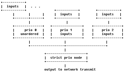
The actual qos tree configuration can be found at arch/arm/boot/dts/keystone-qostree.dtsi.
The device tree has attributes for configuring the QoS shaper. In the sections below we explain the various qos specific attributes which can be used to setup and configure a QoS shaper.
In the device tree we are setting up a shaper that is depicted below
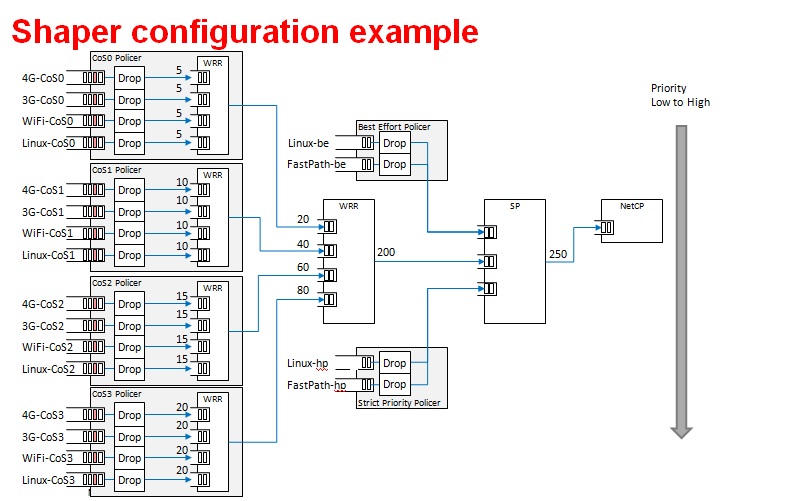
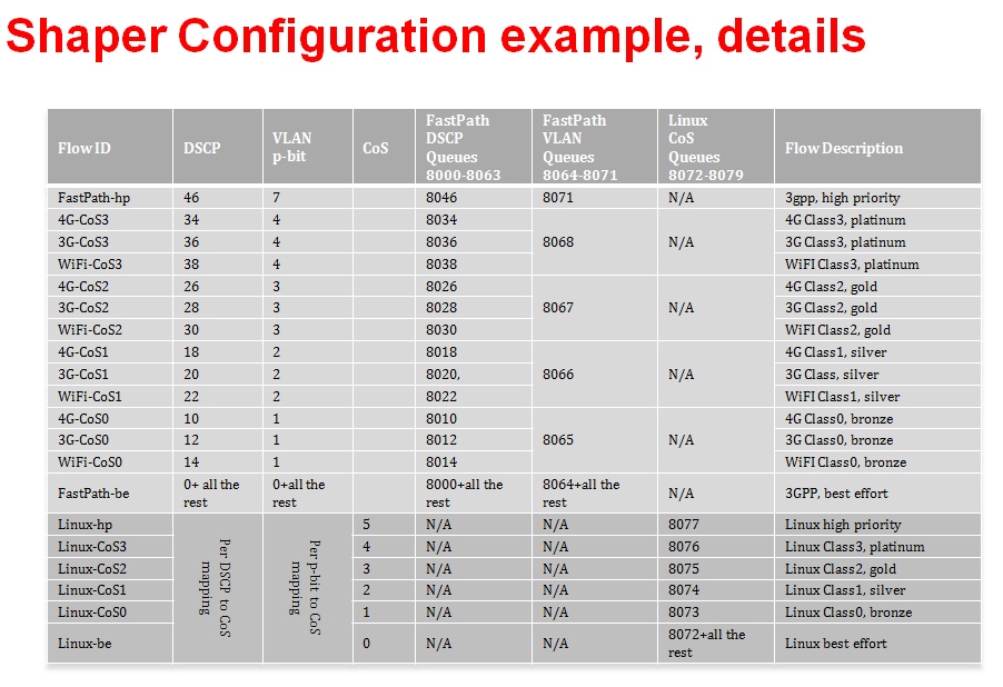
QoS Node Attributes
The following attributes are recognized within QoS configuration nodes:
- “strict-priority” and “weighted-round-robin”
e.g. strict-priority;
This attribute specifies the type of scheduling performed at a node. It is an error to specify both of these attributes in a particular node. The absence of both of these attributes defaults the node type to unordered(first come first serve).
- “weight”
e.g. weight = <80>;
This attribute specifies the weight attached to the child node of a weighted-round-robin node. It is an error to specify this attribute on a node whose parent is not a weighted-round-robin node.
- “priority”
e.g. priority = <1>;
This attribute specifies the priority attached to the child node of a strict-priority node. It is an error to specify this attribute on a node whose parent is not a strict-priority node. It is also an error for child nodes of a strict-priority node to have the same priority specified.
- “byte-units” or “packet-units”
e.g. byte-units;
The presence of this attribute indicates that the scheduler accounts for traffic in byte or packet units. If this attribute is not specified for a given node, the accounting mode is inherited from its parent node. If this attribute is not specified for the root node, the accounting mode defaults to byte units.
- “output-rate”
e.g. output-rate = <31250000 25000>;
The first element of this attribute specifies the output shaped rate in bytes/second or packets/second (depending on the accounting mode for the node). If this attribute is absent, it defaults to infinity (i.e., no shaping). The second element of this attribute specifies the maximum accumulated credits in bytes or packets (depending on the accounting mode for the node). If this attribute is absent, it defaults to infinity (i.e., accumulate as many credits as possible).
- “overhead-bytes”
e.g. overhead-bytes = <24>;
This attribute specifies a per-packet overhead (in bytes) applied in the byte accounting mode. This can be used to account for framing overhead on the wire. This attribute is inherited from parent nodes if absent. If not defined for the root node, a default value of 24 will be used. This attribute is passed through by inheritence (but ignored) on packet accounted nodes.
- “output-queue”
e.g. output-queue = <645>;
This specifies the QMSS queue on which output packets are pushed. This attribute must be defined only for the root node in the qos tree. Child nodes in the tree will ignore this attribute if specified.
- “input-queues”
e.g. input-queues = <8010 8065>;
This specifies a set of ingress queues that feed into a QoS node. This attribute must be defined only for leaf nodes in the QoS tree. Specifying input queues on non-leaf nodes is treated as an error. The absence of input queues on a leaf node is also treated as an error.
- “stats-class”
e.g. stats-class = “linux-best-effort”;
The stats-class attribute ties one or more input stage nodes to a set of traffic statistics (forwarded/discarded bytes, etc.). The system has a limited set of statistics blocks (up to 48), and an attempt to exceed this count is an error. This attribute is legal only for leaf nodes, and a stats-class attribute on an intermediate node will be treated as an error.
- “drop-policy”
e.g. drop-policy = “no-drop”
The drop-policy attribute specifies a drop policy to apply to a QoS node (tail drop, random early drop, no drop, etc.) when the traffic pattern exceeds specifies parameters. The drop-policy parameters are configured separately within device tree (see “Traffic Police Policy Attributes section below). This attribute defaults to “no drop” for applicable input stage nodes. If a node in the QoS tree specifies a drop-policy, it is an error if any of its descendent nodes (children, children of children, ...) are of weighted-round-robin or strict-priority types.
Traffic Police Policy Attributes
The following attributes are recognized within traffic drop policy nodes:
- “byte-units” or “packet-units”
e.g. byte-units;
The presence of this attribute indicates that the dropr accounts for traffic in byte or packet units. If this attribute is not specified, it defaults to byte units. Policies that use random early drop must be of byte unit type.
- “limit”
e.g. limit = <10000>;
Instantaneous queue depth limit (in bytes or packets) at which tail drop takes effect. This may be specified in combination with random early drop, which operates on average queue depth (instead of instantaneous). The absence of this attribute, or a zero value for this attribute disables tail drop behavior.
- “random-early-drop”
e.g. random-early-drop = <32768 65536 2 2000>;
The random-early-drop attribute specifies the following four parameters in order:
low threshold: No packets are dropped when the average queue depth is below this threshold (in bytes). This parameter must be specified.
high threshold: All packets are dropped when the average queue depth above this threshold (in bytes). This parameter is optional, and defaults to twice the low threshold.
max drop probability: the maximum drop probability
half-life: Specified in milli seconds. This is used to calculate the average queue depth. This parameter is optional and defaults to 2000.
Sysfs support
The keystone hardware queue driver has sysfs support for statistics, drop policies and the tree configuration.
root@k2hk-evm:~# cd /sys/devices/platform/soc/soc:qmss@2a40000/qos-inputs-0
root@k2hk-evm:/sys/devices/platform/soc/soc:qmss@2a40000/qos-inputs-0# ls
drop-policies  qos-tree       statistics
root@keystone-evm:/sys/devices/platform/soc/soc:qmss@2a40000/qos-inputs-0#
The above shows the location in the kernel where sysfs entries for the keystone hardware queue can be found. There are sysfs entries for the qos trees (qos-inuputs-0, qos-tree-inputs-1). Within the qos directory there are separate directories for statistics, drop-policies and the qos-tree itself. Each node in the tree is a separate directory entry, starting with the root (tip) entry.
- bytes forwarded
- bytes discarded
- packets forwarded
- packets discarded
cat /sys/devices/platform/soc/soc:qmss@2a40000/qos-inputs-0/statistics/linux-be/packets_forwarded
Drop policy configuration is also displayed for each drop policy. In the case of a drop policy, the parameters can also be changed. This is depicted below. Please note the the parameters that can be modified for tail drop are a subset of the parameters that can be modified for random early drop.
- directory entries to reach the subtrees feeding this node
- the input queues to this node (valid for leaf nodes only)
- the output queue from this node
- the output rate for the node. The current value can be shown by: “cat output_rate”. The value can be modified by: echo ”<val>” > output_rate
- the overhead bytes parameter for the node. The current value can be shown by: “cat overhead_bytes”. The value can be modified by: echo ”<val>” > overhead_bytes
- burst size . The current value can be shown by: “cat burst_size”. The value can be modified by: echo “<val>” > burst_size
- drop_policy . This is the name of the drop policy to be used.
- stats_class associated with node. This is the name of stats class to be used
- the priority of the node (for strict priority nodes only). The current value can be shown by: “cat priority”. The value can be modified by: echo “<val>” > priority
- weight : for wrr nodes. The current value can be shown by: “cat weight”. The value can be modified by: echo “<val>” > weight
Debug Filesystem support
Debug Filesystem(debugfs) support is also being provided for QoS support. To make use of debugfs support a user might have to mount a debugfs filesystem. This can be done by issuing the command (if /debug does not exist on your filesystem, you may need to create the directory first).
mount -t debugfs debugfs /debug
root@keystone-evm:/debug/qos-3# ls
config_profiles  out_profiles     queue_configs    sched_ports
With the debugfs support we will be able to see the actual configuration of
- QoS scheduler ports
- Drop scheduler queue configs
- Drop scheduler output profiles
- Drop scheduler config profiles
root@k2hk-evm:/debug/qos-3# cat sched_ports
port 14
unit flags 15 group # 1 out q 8171 overhead bytes 24 throttle thresh 2501 cir credit 5120000 cir max 51200000
total q's 4 sp q's 0 wrr q's 4
queue 0 cong thresh 0 wrr credit 384000
queue 1 cong thresh 0 wrr credit 384000
queue 2 cong thresh 0 wrr credit 384000
queue 3 cong thresh 0 wrr credit 384000

port 15
unit flags 15 group # 1 out q 8170 overhead bytes 24 throttle thresh 2501 cir credit 5120000 cir max 51200000
total q's 4 sp q's 0 wrr q's 4
queue 0 cong thresh 0 wrr credit 384000
queue 1 cong thresh 0 wrr credit 384000
queue 2 cong thresh 0 wrr credit 384000
queue 3 cong thresh 0 wrr credit 384000

port 16
unit flags 15 group # 1 out q 8169 overhead bytes 24 throttle thresh 2501 cir credit 5120000 cir max 51200000
total q's 4 sp q's 0 wrr q's 4
queue 0 cong thresh 0 wrr credit 384000
queue 1 cong thresh 0 wrr credit 384000
queue 2 cong thresh 0 wrr credit 384000
queue 3 cong thresh 0 wrr credit 384000

port 17
unit flags 15 group # 1 out q 8168 overhead bytes 24 throttle thresh 2501 cir credit 5120000 cir max 51200000
total q's 4 sp q's 0 wrr q's 4
queue 0 cong thresh 0 wrr credit 384000
queue 1 cong thresh 0 wrr credit 384000
queue 2 cong thresh 0 wrr credit 384000
queue 3 cong thresh 0 wrr credit 384000

port 18
unit flags 15 group # 1 out q 8173 overhead bytes 24 throttle thresh 3126 cir credit 5120000 cir max 51200000
total q's 4 sp q's 0 wrr q's 4
queue 0 cong thresh 0 wrr credit 384000
queue 1 cong thresh 0 wrr credit 768000
queue 2 cong thresh 0 wrr credit 1152000
queue 3 cong thresh 0 wrr credit 1536000

port 19
unit flags 7 group # 1 out q 645 overhead bytes 24 throttle thresh 0 cir credit 6400000 cir max 51200000
total q's 3 sp q's 3 wrr q's 0
queue 0 cong thresh 0 wrr credit 0
queue 1 cong thresh 0 wrr credit 0
queue 2 cong thresh 0 wrr credit 0

root@k2hk-evm:/debug/qos-3#
Configuring QoS on an 1-GigE interface
To configure QoS on an interface, several definitions must be added to the device tree:
- Drop policies and a QoS tree must be defined. The outer-most QoS block must specify an output queue number; this may be the 1-GigE NETCP’s PA PDSP 5 (645) or CPSW (648), one of the 10-GigE CPSW’s queues (8752, 8753), or other queue as appropriate.
Example (keystone-qostree.dtsi):
droppolicies: default-drop-policies {
        no-drop {
                default;
                packet-units;
                limit = <0>;
        };
        ...
        all-drop {
                byte-units;
                limit = <0>;
        };
};
Example (keystone-qostree.dtsi):
qostree0: qos-tree-0 {
        strict-priority;                /* or weighted-round-robin */
        byte-units;                     /* packet-units or byte-units */
        output-rate = <31250000 25000>;
        overhead-bytes = <24>;          /* valid only if units are bytes */
        output-queue = <645>;           /* allowed only on root node */
        high-priority {
                ...
        }
        ...
        best-effort {
                ...
        };
};
qostree1: qos-tree-1 {
        strict-priority;                /* or weighted-round-robin */
        byte-units;                     /* packet-units or byte-units */
        output-rate = <31250000 25000>;
        overhead-bytes = <24>;          /* valid only if units are bytes */
        output-queue = <648>;           /* allowed only on root node */
        high-priority {
                ...
        }
        ...
        best-effort {
                ...
        };
};
- QoS inputs must be defined to the hwqueue subsystem. The QoS inputs block defines which group of hwqueues will be used, and links to the set of drop policies and QoS tree to be used.
Example (k2hk-netcp.dtsi):
qmss: qmss@2a40000 {
        ...
        queue-pools {
                ...
                qos {
                        qosinputs0: qos-inputs-0 {
                                qrange                  = <8000 192>;
                                pdsp-id                 = <3>;
                                ...
                                drop-policies           = <&droppolicies>;
                                qos-tree                = <&qostree0>;
                                reserved;
                        };
                        qosinputs1: qos-inputs-1 {
                                values                  = <6400 192>;
                                pdsp-id                 = <7>;
                                ...
                                drop-policies           = <&droppolicies>;
                                qos-tree                = <&qostree2>;
                                reserved;
                        };
                };
        }
};
- A PDSP must be defined, and loaded with the QoS firmware.
Example (k2hk-netcp.dtsi):
qmss: qmss@2a40000 {
       ...
       pdsps {
               ...
               pdsp3@0x2a13000 {
                       firmware = "qos";
                       ...
                       id = <3>;
               };
               pdsp7@0x2a17000 {
                       firmware = "qos";
                       ...
                       id = <7>;
               };
       };
}; /* qmss */
- A NETCP QoS block must be defined. For each interface, an “interface-x” block is defined, which contains definitions for each of the QoS input subqueues to be associated with that interface.
Example (k2hk-netcp.dtsi):
netcp: netcp@2090000 {
        ...
        qos@0 {
                label = "netcp-qos";
                ...
                interfaces {
                        qos0: interface-0 {
                                tx-queues = <645 8072 8073 8074
                                             8075 8076 8077>;
                        };
                        qos1: interface-1 {
                                tx-queues = <645 6472 6473 6474
                                             6475 6476 6477>;
                        };
        };
};
- By default, Linux network traffic will be queued to the interface’s first subqueue. To classify and route packets from Linux to specific QoS queues, the Linux traffic control utility “tc” must be used. First a class-full root queuing discipline must be established for the interface, and then filters may be used to classify packets. These filters can use the “skbedit queue_mapping” action to set the subqueue number for the packet. Here is an example:
# Clear any existing configuration
tc qdisc del dev eth0 root
# Add DSMARK as the root qdisc
tc qdisc add dev eth0 root handle 1 dsmark indices 8 default_index 0
# Create filters to classify packets and route to queues
tc filter add dev eth0 parent 1:0 protocol ip prio 1 \
        u32 match ip dport 5002 0xffff \
        action skbedit queue_mapping 1
tc filter add dev eth0 parent 1:0 protocol ip prio 1 \
        u32 match ip dport 5003 0xffff \
        action skbedit queue_mapping 2
tc filter add dev eth0 parent 1:0 protocol ip prio 1 \
        u32 match ip dport 5004 0xffff \
        action skbedit queue_mapping 3
tc filter add dev eth0 parent 1:0 protocol ip prio 1 \
        u32 match ip dport 5005 0xffff \
        action skbedit queue_mapping 4
tc filter add dev eth0 parent 1:0 protocol ip prio 1 \
        u32 match ip dport 5006 0xffff \
        action skbedit queue_mapping 5
Please refer to the Linux Advanced Routing & Traffic Control how-tos and related manpages available on the Internet for more information on “tc”.
Disabling QoS on an 1-GigE interface
The released “keystone-qostree.dtsi” file contains definitions for two QoS trees which are associated with the first two ports on the 1-GigE interface in the “k2hk-netcp.dtsi” file. These default trees are configured so that traffic queued to interface subqueue 0 will bypass the QoS tree. Only traffic specifically directed to subqueues 1-6 will be processed through the hardware QoS subsystem. This may be sufficient for your needs. However, you may prefer to remove the QoS configuration entirely from the device tree.
To disable QoS on the two 1-GigE interfaces
- delete all the qos related blocks or entries shown in the examples in section Configuring QoS on an 1-GigE interface, namely
- droppolicies: default-drop-policies {...}
- qostree0: qos-tree-0 {...}
- qostree1: qos-tree-1 {...}
- qos-inputs-0 {...}
- qos-inputs-1 {...}
- pdsp3@0x2a13000 {...}
- pdsp7@0x2a17000 {...}
- qos@0 {...}
Configuring QoS on a 10-GigE interface
The following snippets together shows how to remove the QoS tree associated with the second port of the 1-GigE interface and associate it with the first port on the 10-GigE interface. In these snippets, we only depict and highlight the modifications made to the above 1-GigE examples. Contents not shown in the definitions should just be copy and paste from the file k2hk-netcp.dtsi.
Note: this is only for demonstration purpose and is not part of the release.
- Remove “netcp-qos = <&qos1>” from 1-GigE’s netcp@2090000 > netcp-interfaces > interface-1 {...}.
- Remove qos1: interface-1 { ... } from 1-GigE’s netcp qos block.
netcp: netcp@2090000 {
        ...
        qos@0 {
                label = "netcp-qos";
                ...
                interfaces {
                        qos0: interface-0 {
                                tx-queues = <645 8072 8073 8074
                                             8075 8076 8077>;
                        };
                        /* qos1:interface-1 removed */
        };
};
- Modify the output-queue number of qostree1 to that of the transmit queue of the 10-GigE’s first port.
qostree1: qos-tree-1 {
        output-queue = <8752>;           /* allowed only on root node */
};
- Define a qos block in 10-GigE’s netcp@2f00000 > netcp-devices {...}.
netcpx: netcp@2f00000 {
         ...
         netcp-devices {
                ...
               qos@0 {
                       label = "netcpx-qos";
                       compatible = "ti,netcp-qos";
                       tx-channel = "xnettx";

                       interfaces {
                               qos1: interface-1 {
                                       tx-queues = <645 6472 6473 6474
                                                       6475 6476 6477>;
                               };
                       };
               };
        };
};
- Finally, add a qos interface to 10-GigE’s interface-1:
netcpx: netcp@2f00000 {
         ...
         netcp-interfaces {
                ...
               interface-1 {
                        ...
                        netcp-xqos = <&qos1>;
               };
        };
};
Using Accumulated queues for Network interfaces
Accumulated queues allows interrupt pacing for rx queue interrupts. Accumulated queue range is defined in DTS under the queue-pools. See keystone-<SoC>-netcp.dtsi
accumulator {
        acc-low-0 {
                qrange = <480 32>;
                accumulator = <0 47 16 2 50>;
                interrupts = <0 226 0xf01>;
                multi-queue;
                qalloc-by-id;
        };
};
netcp: netcp@2000000 {

// other bindings

       netcp-interfaces {
               interface-0 {
                       rx-channel = "netrx0";
                       rx-pool = <1024 12>;
                       tx-pool = <1024 12>;
                       rx-queue-depth = <128 128 0 0>;
                       rx-buffer-size = <1518 4096 0 0>;
                       rx-queue = <8704>; <============================= replace this with 480
                       tx-completion-queue = <8706>;
                       efuse-mac = <1>;
                       netcp-gbe = <&gbe0>;
                       netcp-pa = <&pa0>;
               };
               interface-1 {
                       rx-channel = "netrx1";
                       rx-pool = <1024 12>;
                       tx-pool = <1024 12>;
                       rx-queue-depth = <128 128 0 0>;
                       rx-buffer-size = <1518 4096 0 0>;
                       rx-queue = <8705>;<============================= replace this with 481
                       tx-completion-queue = <8707>;
                       efuse-mac = <0>;
                       local-mac-address = [02 18 31 7e 3e 6f];
                       netcp-gbe = <&gbe1>;
                       netcp-pa = <&pa1>;
               };
       };
};
If PA is used, make sure rx-route which specifiy start queue is also replaced as shown below.
netcp: netcp@2000000 {

// other bindings
       netcp-devices {

               // other bindings
               pa@0 {

                     // other bindings

                     rx-route                = <8704 22>;        <=============================== change this to <480 22>

                     // other bindings

               };
       };
};
K2HK EVM Gigabit MDC/MDIO Signal Integrity Issue
Due to a MDC/MDIO signal integrity issue in the EVM that gets showed up when a RTM Breakout Card is connected to a K2HK EVM, the Gigabit Ethernet link can go down/up repeatedly with no apparent reason except with some debug prints similar to the following shown:
[   21.445070] netcp-1.0 2620110.netcp eth0: Link is Down
[   22.175392] netcp-1.0 2620110.netcp eth0: Link is Up - 1Gbps/Full - flow control off
[   24.065092] netcp-1.0 2620110.netcp eth1: Link is Down
[   34.175092] netcp-1.0 2620110.netcp eth0: Link is Down
Software Workaround
A workaround that helps to avoid the issue is to disable the Gigabit MDIO and modify the Gigabit Ethernet interface link type to SGMII_LINK_MAC_PHY_NO_MDIO (4) by making the following changes in the default K2HK devicetree bindings.
diff --git a/arch/arm/boot/dts/keystone-k2hk-evm.dts b/arch/arm/boot/dts/keystone-k2hk-evm.dts
index ff1c0fc..0cfa003 100644
--- a/arch/arm/boot/dts/keystone-k2hk-evm.dts
+++ b/arch/arm/boot/dts/keystone-k2hk-evm.dts
@@ -200,6 +200,7 @@
        };
 };
+/*
 &mdio {
        status = "ok";
      thphy0: ethernet-phy@0 {
@@ -212,6 +213,7 @@
                reg = <1>;
        };
 };
+*/

 &gbe_serdes {
        status = "okay";
diff --git a/arch/arm/boot/dts/keystone-k2hk-netcp.dtsi b/arch/arm/boot/dts/keystone-k2hk-netcp.dtsi
index f51d20b..0d98f1f 100644
--- a/arch/arm/boot/dts/keystone-k2hk-netcp.dtsi
+++ b/arch/arm/boot/dts/keystone-k2hk-netcp.dtsi
@@ -370,14 +370,14 @@ netcp: netcp@2000000 {
gbe0: interface-0 {
phys = <&serdes_lane0>;
slave-port = <0>;
- link-interface = <1>;
- phy-handle = <ðphy0>;
+ link-interface = <4>;
+ /* phy-handle = <ðphy0>; */
};
gbe1: interface-1 {
phys = <&serdes_lane1>;
slave-port = <1>;
- link-interface = <1>;
- phy-handle = <ðphy1>;
+ link-interface = <4>;
+ /* phy-handle = <ðphy1>; */
};
};
Hardware Fix
As of Oct 10, 2016, it is reported that Mistral Solutions Inc. (vendor of the RTM-BOC) has produced a newer version (v2.16) of the RTM-BOC that has fixed the signal integrity issue. However the hardware fix has not yet been verified by the software development team.
10G SerDes Auto-Configuration
The 10G ethernet switch found in K2HK and K2E includes a MCU which allows running a firmware to perform SerDes configuration without the intervention of the switch driver.
Enabling Auto-Configuration
To enable 10G SerDes auto-configuration, add the following in keystone-k2hk-evm.dts or keystone-k2e-evm.dts.
+&xgbe_subsys {
+       status          = "okay";
+};
+
+&xgbe_pcsr {
+       status          = "okay";
+};
+
+&xgbe_serdes {
+       status          = "okay";
+
+       clocks          = <&clkxge>;
+       clock-names     = "xge_clk";
+
+       mcu-firmware {
+               status = "okay";
+
+               lane@0 {
+                       status = "okay";
+               };
+
+               lane@1 {
+                       status = "okay";
+               };
+       };
+};
+
+&netcpx {
+       status          = "okay";
+};
Usage Note
- After the DUT bootup is completed, notice the all the enabled 10G interfaces are up and running. Then verify the 10G interfaces as usual, such as using the ping command.
- Due to constraints there are several usage notes concerning the firmware:
- When autonegotiation occurs there is a reset asserted on the lane
that affects the MAC layer and switch.
- During a simultaneous boot of two devices they will sync and autonegotiate before the aforementioned layers are configured. There is no issue in this scenario.
- If a single device is reset this will cause autonegotiation to occur again. This will reset the lane of the device that stayed persistently on. When this happens, re-program the MAC_CONTROL register for that lane, otherwise, an interface toggle using ‘ifconfig’ is sufficient to reconfigure the interface back to a working state.
- When switching between a non-FW configuration and a FW configuration a POR is required.
- Due to errata KeyStoneII.BTS_errata_advisory.29:10GbE PCS Causes
Data Corruption, occasionally on link negotiation there may be high
levels of packet loss.
- The symptoms of this are high packet loss, CRC and alignment errors, and 0xff block errors in a small time period.
- When this case is detected, assert SerDes Signal Detect low to
reforce an autonegotiation, then follow the above procedure for an
interface toggle.
- Signal detect is located at register LANE_004, BITS[2:1]. BIT[2] is override enable and BIT[1] is the override value. Once override enable is set it will force the override value as the value of signal detect. To force signal detect low, the proper write would be BITS[2:1] = 0x2. Once this has been set the firmware will respond to the lane being down and re-do auto-negotiation, automatically clearing the signal detect low state.
- If there is a total loss of signal, restarting the firmware may help.
- The firmware can be restarted by writing to CPU_CTRL register, POR_EN bit 29. Set this bit high, then set it low with at least 10ms in between.