7.1. PRU ICSS Profibus Slave User Guide
- Introduction
- Release 01.00.02
- System Requirements
- Reference Documents
- Directory Structure
- Generating Project files
- Board Setup
- Running and configuring the Profibus slave application
- Watch dog Timer support in Firmware to detect Host CPU crash
- Enabling Profibus support in Boards without inbuilt RS485 Connector
7.1.1. Introduction
PRU-ICSS Profibus Slave package is designed for the Sitara processor family (with PRU-ICSS IP) to enable customers add Profibus Slave protocol support to their system.
7.1.2. Release 01.00.02
Release Date: June 2018
7.1.3. System Requirements
7.1.3.1. Supported Devices
- AM572x IDK 1.3A/B
- AM571x IDK 1.3A
- AM437x IDK
- AM335x ICEV2
- AMIC11x ICE
7.1.3.2. Component Version
This release requires Processor SDK RTOS, see Processor SDK Getting Started Guide
| Component | Version |
|---|---|
| Processor SDK RTOS for AM57xx | 4.3.0 |
| Processor SDK RTOS for AM437x | 4.3.0 |
| Processor SDK RTOS for AM335x | 4.3.0 |
| Processor SDK RTOS for AM65X | 4.3.0 |
7.1.5. Directory Structure
|   |--- docs
|       |---Industrial_Protocol_Package_Getting_Started_Guide.pdf
|       |---Industrial_Protocol_Package_Software_Developer_Guide.pdf
|       |---PRU_ICSS_Profibus_Slave_User_Guide.pdf
|       |---PRU_ICSS_Profibus_Slave_Release_Notes.pdf
|       |---Profibus_Slave_Datasheet.pdf
|       |---PRU-ICSS-Profibus_Slave_01.00.xx_manifest.html

|   |--- examples
       |--- board
|           | --- common
|           | --- iceAM335x
|           | --- iceAM437x
|           | --- idkAM571x
|           | --- idkAM572x
|           | --- include

|       |--- profibus_slave
|           | --- AM57xx
|           | --- AM335x
|           | --- AM437x
|           | --- APP
|           | --- GSD
|           | --- include

|   |--- protocols
|       |--- profibus_slave
|               |--- docs
|                       |--- doxygen
|               |--- firmware
|               |--- include
|               |--- projects

|   |--- third_party
|       |--- protocols
|               |--- profibus_slave
|                           |--- include
|                           |--- stack_lib
|                                    |--- am335x
|                                            |--- a8
|                                    |--- am437x
|                                            |--- a9
|                                    |--- am57xx
|                                            |--- a15
Note
Refer to install path to get updated view for any changes in directory structure
7.1.6. Generating Project files
Note
- Unlike [legacy Industrial SDK],
- the CCS project files are not readily available in the protocol package installer. The steps that are involved to generate CCS project files with the help of the Batch file or Shell script are as explained below.
7.1.6.1. Steps to generate Project files
- Setup the environment variables
- Edit the file
[INSTALL-DIR]/protocols/<protocol name>/projects/projectCreate.bat or .shto align to the environment in your machine. All these paths should be accurate and mandatory, and will cause errors otherwise- CCS_INSTALL_DIR - Set the path where the recommended version of CCS is installed in user machine(The path upto where folder ‘eclipse’ is located.)
- CCS_WORKSPACE_LOC - Set the CCS workspace location. This folder will be created if it doesn’t exist already.
- Edit the file
Note
- Use the default path provided for CCS_WORKSPACE_LOC as a reference.
- The ‘user’ needs to be replaced by actual user account name in the PC
- IA_SDK_HOME - Specify the IA_SDK_HOME based on the directory where the industrial package is installed. If the package is installed in a custom directory, make sure this path is modified properly.
- PDK_INSTALL_PATH - Set the path where PDK RTOS package is installed (Refer to default path in projectCreate.bat)
- PROJECT_CREATE_DIR - Set the folder where the created project will be kept. User can import the projects from this directory to CCS
- PROJECT_CREATE_OPTIONS_FILE_DIR - Specify the directory where the project create options files are kept. This folder contains the *.txt files which specify the project settings (linked files, predefined symbols, compiler and linker options for a specific project)
- Open Command/Shell Prompt and navigate to
[INSTALL-DIR]/protocols/<protocol name>/projects - Run projectCreate.bat or projectCreate.sh. The batch file intakes three mandatory command line arguments (The mandatory arguments are case sensitive!)
Usage format: projectCreate.bat [SOC] [PROCESSOR] [PROJECT_NAME]
- [SOC]
- The valid values for first command line argument [SOC] are
- AM571x - To generate a project specific to AM571x
- AM572x - To generate a project specific to AM572x
- AM335x - To generate a project specific to AM335x
- AMIC11x - To generate a project specific to AMIC11x
- AM437x - To generate a project specific to AM437x
- The valid values for first command line argument [SOC] are
- [PROCESSOR]
- The valid values for second command line argument [PROCESSOR] are
- arm - To generate a project specific to ARM core
- The valid values for second command line argument [PROCESSOR] are
- [PROJECT_NAME]
- The valid values for third command line argument [PROJECT_NAME]
to be used with Profinet slave installer package
- profibus_slave - to generate Profibus slave application project
- The valid values for third command line argument [PROJECT_NAME]
to be used with Profinet slave installer package
Note
Ensure that Code Composer Studio is not running when executing projectCreate.bat or projectCreate.sh. If not, the eclipse may throw errors
Usage example 1 : projectCreate.bat AM572x arm profibus_slave
To generate the project files for Profibus slave application for AM572x ARM core by overwriting the project if it is already existing in PROJECT_CREATE_DIR\PROJECT_NAME_SOC_PROCESSOR
Usage example 2 : projectCreate.bat AM335x arm profibus_slave
To generate the project files for Profibus slave application for AM335x ARM core by overwriting the project if it is already existing in PROJECT_CREATE_DIR\PROJECT_NAME_SOC_PROCESSOR
Note
If the project create is successful, the generated project files will be found in
[INSTALL-DIR]/protocols/<protocol name>/projects/PROJECT_NAME/SOC
7.1.6.1.1. More info
The projectCreate.bat or.sh utilizes the project arguments provides in
[INSTALL-DIR]/protocols/<protocol name>/projects/ccsproject_args to
generate the project file
7.1.7. Board Setup
- After powering on the board the bootloader will load the APP from SDMMC/SPI flash/NOR flash into DDR/Internal RAM/Cache
- The boot logs can be seen on serial console. Serial console need to be configured with 8 bit data, 1 stop bit and with the baud rate of 115200.
7.1.8. Running and configuring the Profibus slave application
Profibus slave application provides the feature of configuring the slave address through the UART interface provided and if UART interface is not present profibus application works with default configuration. After successful powering on the board, application waits for 5 sec for the keyboard input data through the UART. If it doesn’t get (UART cable not connected or user didn’t press the keyboard in 5 sec). Application configures the slave with the slave address of 4. In case of board is connected to UART cable, on power on APP will print the menu on the serial console.
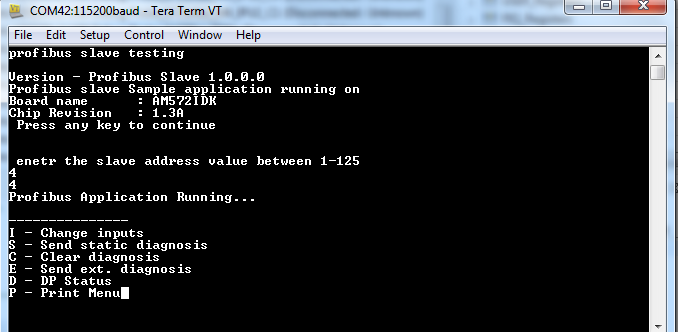
- The input can be changed by pressing ‘i’ on keyboard
- The master output updates are seen on serial console and output byte 3 toggles the LEDs on top of J17 (in IDK) or below J9 (in ICE) in a pattern sent by the master on byte3 (enable watchdog/modify I/O)
- ‘d’ gives the DP status - 0x80 or 0x81 indicates the data exchanges, 0x0 indicates that data exchange is stopped
7.1.9. Watch dog Timer support in Firmware to detect Host CPU crash
Profibus Slave Application uses Watchdog timer to detect the CPU crash.This support is enabled by deafult. User can disable the feature by removing the macro “ENABLE_WATCHDOG_SUPPORT” in the file “profi_misc.h”. The time out can be configured by changing the value of the macro “WATCHDOG_EXPIRE_TIME”. Watchdog task is created if the macro ENABLE_WATCHDOG_SUPPORT is enabled. The task will continuously reset the PDI Watchdog Timer in the PRUSS periodically so that the time out does not occur. The profibus firmware will be polling the timeout event and once the time out is detected, the Data exchange will be disabled.
7.1.10. Enabling Profibus support in Boards without inbuilt RS485 Connector
An external RS485 isolated transceiver is used to validate profibus support on the boards without inbuilt connector. Connections from the transceiver are made to the prx_uart0_rxd, prx_uart0_txd and prx_pru0_gpoy via expansion connectors. prx_pru0_gpoy is used as Tx Enable pin. Below table has the list of TX Enable pins used by the applications
| Board | GPO used | Ball number |
|---|---|---|
| AMIC11x ICE | PR1_PRU0_PRU_R30_5 | C13 |
| AM437x IDK ICSS0 | PR0_PRU0_GP01 | N22 |
| AM437x IDK ICSS1 | PR1_PRU0_GPO6 | C20 |