EVM430 CAPMINI
Take me back to Development Tools
The EVM430-CAPMINI is an easy-to-use evaluation board for the MSP430FR2512 capacitive-touch-sensing microcontroller. It demonstrates the key features of CapTIvate technology such as ultra-low power and ease of use. Onboard CapTIvate HID bridge tool support real time tuning with CapTIvate Design Center. The board includes 4 touch buttons and 4 LEDs for creating a simple user interface. It also provides a buzzer for advanced application. The board can be powered by USB cable as well as onboard CR1632 coin battery which enabling stand-alone demonstration.
This chapter of the CapTIvate Technology Guide contains the following sections:
To order a EVM430-CAPMINI, visit the tool folder.
Overview
Out of the box, the EVM430-CAPMINI powers up as a 4-key touch-to-sound demo. User can play the C, E, G, and B notes through the on-board speaker by tapping the corresponding capacitive touch buttons. A corresponding RED led above the button also show the status of the keypad. If user want to play notes D, F, and A, simply touch both buttons below the desired note. Sensor data streaming is enabled out of the box to the CapTIvate Design Center via the UART interface. The EVM430-CAPMINI may also be programmed and debugged via the Spy-Bi-Wire programming connector and the use of MSP-FET or ez-FET on Launchpad.
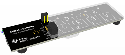
Fig. 385 EVM430-CAPMINI
Key Features
The EVM430-CAPMINI has the following key features:
Four capacitive touch sensing buttons
Features the MSP430FR2512 MCU
Supports single and multi-touch
LEDs to indicate a touch event
On-board audio feedback
Plays unique tone for each button/pair
Two power options for touch evaluation
CR1632 battery holder for portable operation
USB port for operating without battery
Dedicated HID serial communications bridge
No need to install HID drivers
Supports I2C and UART
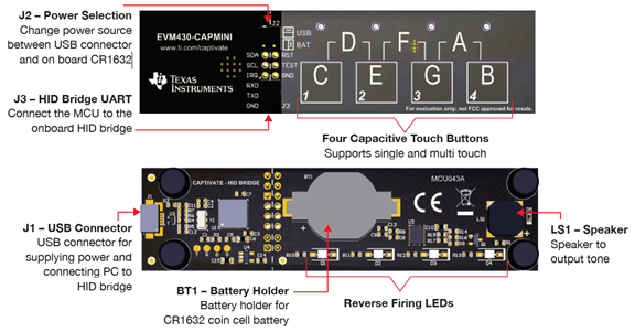
Fig. 386 EVM430-CAPMINI
Key Devices
The EVM430-CAPMINI features the following integrated circuit devices:
MSP430FR2512 ultra-low-power MCU with noise-tolerant CapTIvate technology
What’s Included
The EVM430-CAPMINI comes with the following hardware and software:
Kit Contents
1 EVM430-CAPMINI evaluation board
1 Micro USB cable
1 Quick start guide
Software Examples
The following software example is available to run on the MSP430FR2512 MCU on the EVM430-CAPMINI:
EVM430-CAPMINI out-of-box demonstration (pre-programmed on a new EVM430-CAPMINI)
Getting Started
This section outlines how to get started with the kit.
Out-of-Box Experience
Required Tools
The latest CapTIvate Design Center PC GUI Tool must be installed on a host PC, Mac, or Linux machine
A EVM430-CAPMINI evaluation board programmed with the EVM430-CAPMINI-Demo firmware example
A micro-USB cable is required to connect the EVM430-CAPMINI to the host PC
A CR1632 battery to power the board using battery (Optional)
Assumptions This guide assumes that CapTIvate Design Center is already installed on the host PC. For installation instructions, see the CapTIvate Design Center chapter.
Step 1: Hardware Setup
EVM430-CAPMINI was designed to accommodate various powering methods, including through the USB HID Bridge as well as onboard CR1632 coin battery. The jumper J2 is used to choose the power supply.
USB Power Supply:
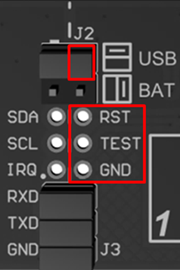
Connect J2 horizontally.
Connect GND on jumper J3.
Battery Power Supply:
Connect J2 vertically.
Remove RXD on jumper J3 to avoid back-power the USB device to extend the battery life.
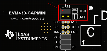
Fig. 387 EVM430-CAPMINI
Step 2: Running the Out of Box Demo
By default after power up, EVM430-CAPMINI development kit enters wake-on-proximity mode. All the LEDs on the board are off. In this state, CPU stays in low power mode 4 with the hardware state machine actively scanning the touch sensor at 10Hz until a button is touched. The overall system average power consumption is only 4 uA.
Touch the buttons on the board will wake up the CPU, the LED will be on while the touch detection is true. At the same time the speaker will play a unique tone for each button. With the combination key the board can play C,D,E,F,G,A,B.
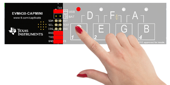
Fig. 388 EVM430-CAPMINI
After removing the finger away from the board, all the LEDs are off. The EVM430-CAPMINI evaluation kit will enter wake-on-proximity mode in 10 seconds.
Step 3: Using CapTIvate Design Center
Connect the EVM430-CAPMINI to a host computer with a micro-USB cable. Connect TXD RXD on jumper J3. Open CapTIvate Design Center on the host computer.
Fig. 389 EVM430-CAPMINI
Select File -> Project Open from the menu bar. Then select the EVM430-CAPMINI-Demo project folder, and select Open.
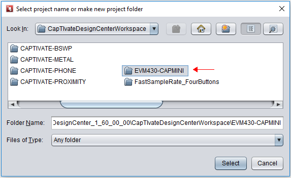
Fig. 390 EVM430-CAPMINI
When the project opens, the design canvas should match the image below. There are two objects in this design:
MSP430FR2512IRHL controller
keypadSensor button group
With the EVM430-CAPMINI connected to the host computer via USB, select Communications -> Connect from the menu bar in CapTIvate Design Center to enable target communications. At this point, when you touch a button, the button status is reflected in the CapTIvate Design Center.
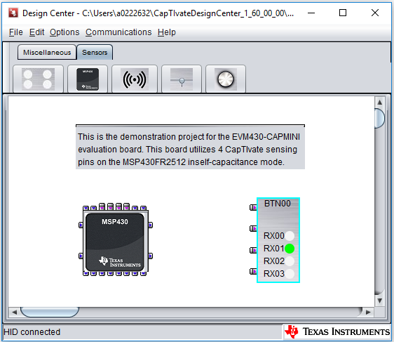
Fig. 391 EVM430-CAPMINI
*Note that during wake-on-touch mode MSP430FR2512 is in sleep mode, and the communication with the CapTIvate Design Center is also stopped.
Open the keypadSensor customizer by double-clicking the keypadSensor icon on the canvas. The Channel Bar Chart view will open by default. Touch any of the keys on the EVM430-CAPMINI to view the response in the customizer. All sensors on the EVM430-CAPMINI are self capacitance sensors. This means that touching a sensor increase the capacitance of the electrode, causing the conversion result (in charge transfer counts) to decrease. The capture below shows the response on button 1 when it is pressed. The default Channel Bar Chart tab is ideal for examining threshold levels.
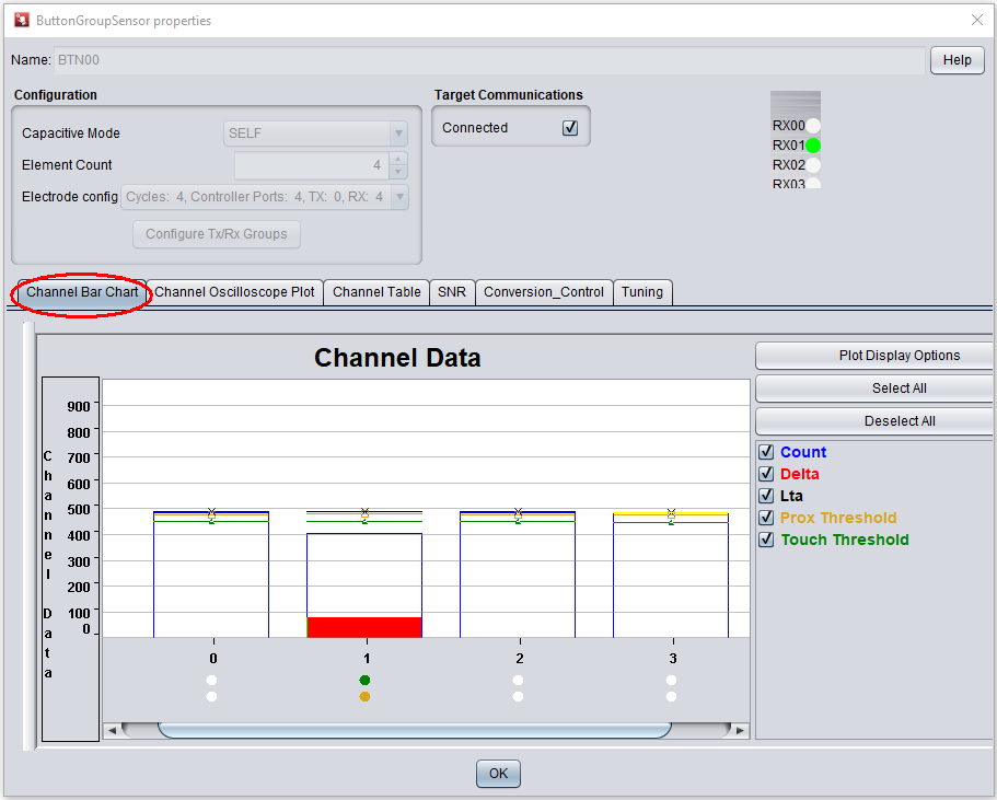
Fig. 392 EVM430-CAPMINI
To view a histogram of a touch, switch to the Channel Oscilloscope Plot. The oscilloscope plot is ideal for examining filter performance and noise immunity.
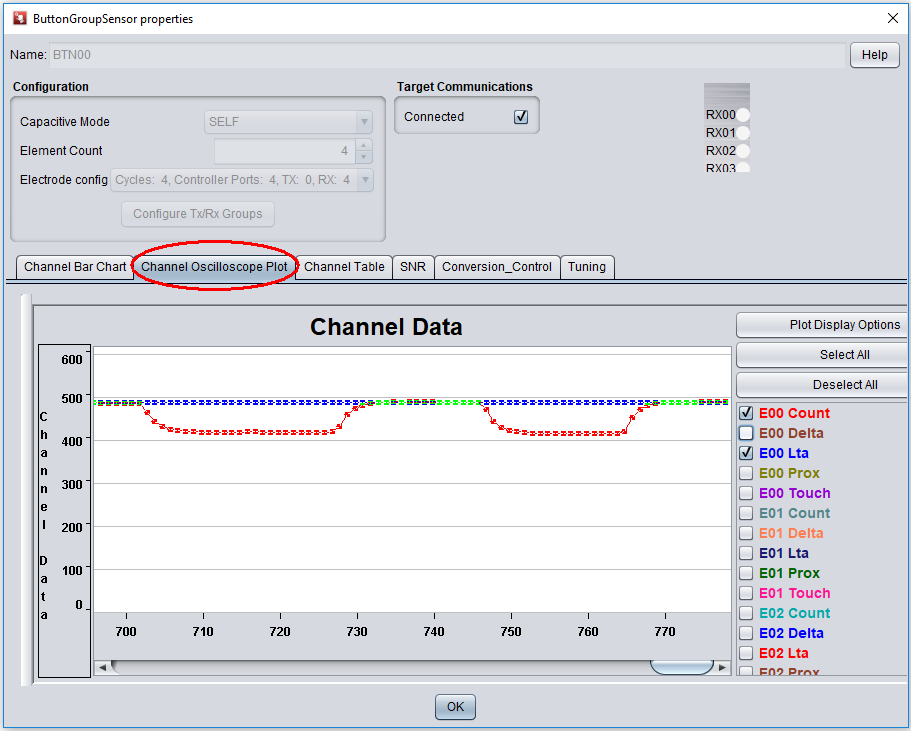
Fig. 393 EVM430-CAPMINI
To view and tune the sensor performance, switch to the Conversion-Control and Tuning panel. Modify the desired parameters then click “Apply”. The new parameters will apply to the board immediately and saved in FRAM as well.
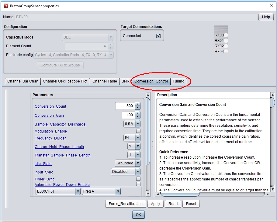
Fig. 394 EVM430-CAPMINI
Hardware
The EVM430-CAPMINI hardware contains many jumpers and connectors to enable various use-cases. This section describes hardware configuration.
Mechanical Design
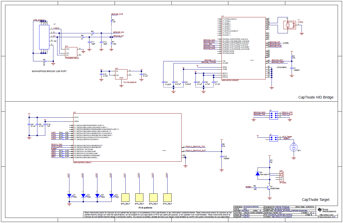
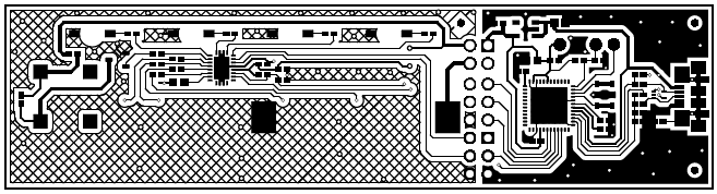
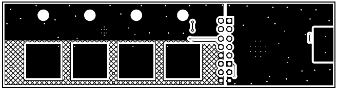
The EVM430-CAPMINI is a 2-layer, 1.6mm thick FR4 printed circuit board and it consists of 2 parts: CapTIvate HID Bridge and CAPMINI touch panel.
CapTIvate HID Bridge is a tool which provides UART and IIC communication interfaces between CapTIvate MCUs and CapTIvate Design Center. For more details, refer to CapTIvate HID Bridge chapter.
CAPMINI panel is a touch sensor panel with a 2mm acrylic overlay material bonded to the PCB using 3M 467MP adhesive. The 2mm overlay represents a typical product overlay thickness. LED illumination is provided from the bottom side of the board through LED through holes in the PCB. Speaker and CR1632 coin battery holder are also provided from the bottom side of the board.
Jumpers and connectors
The EVM430-CAPMINI has jumpers for CAPMINI panel power supply selection and connectors for HID bridge interfaces.
Power supply select jumper
The CAPMINI can be powered by a replaceable 3V lithium coin cell or via the micro-USB connector.
User can select between power operations by placing the on-board selection jumper J2 vertically for battery operation, or horizontally for micro-USB operation, as noted by the diagram to the right of the jumper.
USB Power Supply:
Connect J2 horizontally.
Connect GND on jumper J3.
Battery Power Supply:
Connect J2 vertically.
Remove RXD on jumper J3 to avoid back-power the USB device to extend the battery life.
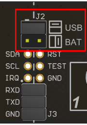
Fig. 395 EVM430-CAPMINI
CapTIvate HID Bridge Interface
CapTIvate HID Bridge tool provides two kinds of interfaces to user, UART and I2C.
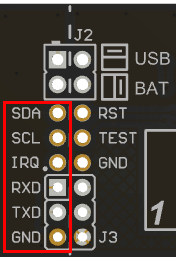
Fig. 396 EVM430-CAPMINI
With this HID bridge user can connect CAPMINI panel directly to the CapTIvate Design Center software by connecting TXD and RXD signals on jumper J3.
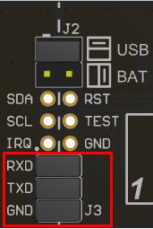
Fig. 397 EVM430-CAPMINI
User can also connect own CapTIvate MCU boards to these interfaces and use it’s HID bridge communications.
Software Example
This section describes the software example which is available for the EVM430-CAPMINI. The EVM430-CAPMINI ships pre-programmed with the example software.
Example Project Locations
During the CapTIvate™ Design Center installation process, example CapTIvate Design Center projects and EVM430-CAPMINI MSP430FR2512 firmware projects are placed in the user’s home directory under “CaptivateDesignCenter/CaptivateDesignCenterWorkspace”. On Windows operating system, this would be:
C:/Users/USERNAME/CapTIvateDesignCenter_X_XX_XX_XX/CapTIvateDesignCenterWorkspace/EVM430-CAPMINI
EVM430-CAPMINI Out-of-Box Software Example
The EVM430-CAPMINI project is the out-of-box demonstration software project. This is the software that comes pre-programmed from TI on the EVM430-CAPMINI. It is also the software that enables the LED indication and speaker features.
This software example enables the following key out-of-box functionality:
A 4-key numeric keypad sensor
LED and speaker indication when touch the key
Wake-on-proximity mode to achieve 4uA stand by power consumption
Real time save tuning parameters to on-chip FRAM
Bi-directional UART communication with the CapTIvate Design Center using the CapTIvate communications library
To begin working with this panel, go through the steps for running an example project and open the EVM430-CAPMINI project.