CAPTIVATE-FR2676
Take me back to Development Tools
The CAPTIVATE-FR2676 is an MCU module featuring the MSP430FR2676 capacitive touch sensing microcontroller (MCU) with CapTIvate technology. The CAPTIVATE-FR2676 module enables you to evaluate self, mutual and metal capacitive touch when combined with the CAPTIVATE-BSWP, CAPTIVATE-PHONE, CAPTIVATE-METAL demo panels respectively.
This chapter of the CapTIvate Technology Guide contains the following sections:
To order a CAPTIVATE-, visit the tool folder.
Overview
The CAPTIVATE-FR2676 comes pre-programmed with an “Out-of-Box” experience that demonstrates self-capacitive buttons, slider, wheel and “Wake-on-Proximity low power operation when combined with the CAPTIVATE-BSWP panel. This combination is used in the Workshop(Getting Started) chapter of this tech guide, which is recommended place to learn how to create your first project and get your touch application up and running in less than 5 minutes without having to write a single line of code.
The CAPTIVATE-FR2676 can be programmed and debugged via the 20-pin CapTIvate programming connector and the use of a CAPTIVATE-PGMR module.
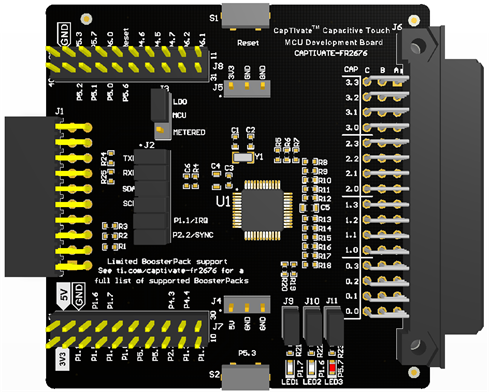
Fig. 275 CAPTIVATE-FR2676
Key Features
Sensor Connector, 48-pin compatible with all CapTIvate demonstration panels, such as CAPTIVATE-BSWP
16 CapTIvate IO
5 General Purpose IO
I2C (EUSCI_B1)
+3.3V
+5V (VBUS)
20-pin CAPTIVATE-PGMR Programming Connector
Two wire “Spy-Bi-Wire” MCU programming
Serial Communication with HID bridge UART (EUSCI_A0) and I2C (EUSCI_B0)
Two +3.3V supplies (selected by jumper)
Normal operation (can power MCU and other +3.3V devices)
Measure MCU current in Code Composer Studio using EnergyTrace&trade
40-pin BoosterPack Connector Compatible
Key Devices
The CAPTIVATE-FR2676 features the following integrated circuit devices:
MSP430FR2676 ultra-low-power MCU with noise-tolerant CapTIvate technology
What’s Included
The CAPTIVATE- comes with the following hardware and software:
Kit Contents
CAPTIVATE-FR2676 MCU Board (pre-programmed with an “Out-of-Box” experience)
1 Micro USB cable
Software Examples
The software examples are available to run on the CAPTIVATE-FR2676 MCU module and can be found in Example Project Locations:
FR2676-CAPTIVATE-BSWP (out-of-box demonstration)
FR2676-CAPTIVATE-PHONE
FR2676-CAPTIVATE-METAL
FR2676-Backchannel-UART (Example Setup)
FR2676-UltraLowPower_FourButtons
Getting Started
This section outlines how to get started with the CAPTIVATE-FR2676 MCU module.
CAPTIVATE- Out-of-Box Software Example
This out-of-box experience describes how to use the CAPTIVATE-FR2676 with the CAPTIVATE-PGMR module and CapTIvate Design Center.
Required Tools
The latest CapTIvate Design Center PC GUI Tool must be installed on a host PC, Mac, or Linux machine
A CAPTIVATE-PGMR module is required to interface the CAPTIVATE- to the host PC
A CAPTIVATE-FR2676 programmed with the CAPTIVATE–Demo firmware example
A micro-USB cable is required to connect the CAPTIVATE-PGMR to the host PC
Software Installation
Install the CapTIvate™ Design Center GUI on your PC, Linux, or MAC computer (note the requirements).
Install a development environment (IDE). TI’s Code Composer Studio v6.1.0 and IAR Embedded Workbench v6.30 or greater are supported.
Connect Hardware
Connect the CAPTIVATE-FR2676 MCU module and CAPTIVATE-PGMR module together.
Connect the desired sensing panel to the CAPTIVATE-FR2676 module. The out-of-box experience uses the CAPTIVATE-BSWP panel.
Connect the micro-USB cable between the CAPTIVATE-PGMR programmer PCB and your computer
Verify that LED2 and LED5 (power good LED’s) on the CAPTIVATE-PGMR module are lit, and that LED4 (HID-Bridge enumeration) is blinking.
Click to view a typical board setup.
Hardware
The CAPTIVATE-FR2676 hardware contains many connection options to enable various LaunchPad use-cases and CapTIvate evaluation use-cases. This section describes hardware configuration.
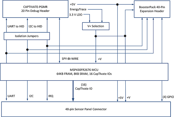
Connections
The CAPTIVATE-FR2676 has connection points for interfacing to a LaunchPad, a CAPTIVATE-PGMR module, and demonstration panels.
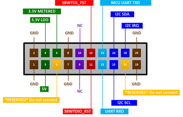
There is a 20-pin female debug connector on the top of the PCB. This connector provides power, SBW, UART, and I2C connectivity with the CAPTIVATE-PGMR module.
There is a 48-pin female sensor panel connector on the bottom of the PCB. All capacitive sensing IO are brought out to this connector, as well as power and I2C.
There is a 40-pin BoosterPack ecosystem header provision in the PCB, to allow the CAPTIVATE-FR2676 PCB to be a BoosterPack to another LaunchPad.
Programmer Connector
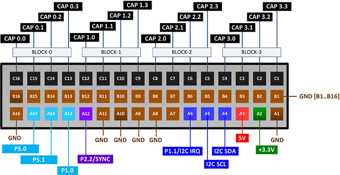
Sensor Panel Connector
The 48-pin sensor panel connector supports up to 16 CapTIvate IO channels. The center row is grounded on this board. In addition to the CapTIvate channels, the EUSCI_B0 I2C signals are available, allowing the MSP430FR2676 to control I2C slave devices, such as LED or Haptics drivers. To power those external devices, +5V and +3.3 (VCC_LDO) is provided. There are also (5) general purpose IO available to the application.
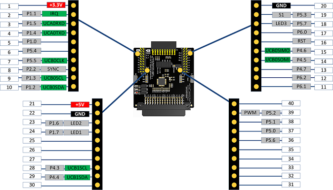
LaunchPad Connector (BoosterPack Header)
The CAPTIVATE-FR2676 features 40-pin BoosterPack standard headers. These headers are top-side only, meaning that the CAPTIVATE-FR2676 is intended to be used at the bottom of a LaunchPad stack. This allows LCD displays on LaunchPads to be visible while using the keypad. The BoosterPack header pinout is shown below.
Power
Programming/Debug
The MSP430FR2676 MCU on this CAPTIVATE-FR2676 PCB is designed to be programmed and debugged through its Spy-Bi-Wire Interface. The full JTAG connection is not available on this PCB.
Note The eZFET™ back-channel UART feature is supported on the CAPTIVATE-FR2676 if R25 and R24 0 ohm resistors are populated on the PCB.
Communication
The MSP430FR2676 MCU communicates with a dedicated USB HID Bridge MCU located on the CAPTIVATE-PGMR PCB using UART or I2C communication to send sensor data and status to the CapTIvate Design Center as part of the sensor design and tuning process. A compact communications protocol is provided as part of the CapTIvate™ software library along with UART and I2C drivers. Both are located in the MSP430FR2676 ROM to minimize the impact on the FRAM memory footprint. The communications protocol is described in the HID Bridge Chapter.
When used with CapTIvate™ protocol, the UART operates in a full duplex mode using RX and TX pins, and the I2C operates as an I2C Slave using SDA and SCL pins with an additional pin P1.2/IRQ to generate interrupt requests.
Jumpers are provided to allow isolation between the MSP430FR2676 and the 20-pin Programming and Communications connector, if one or more of the I/O pins need to be re-purposed. Pull up resistors for I2C SDA, SCL and IRQ signals are provided on the “isolated” side of jumpers.
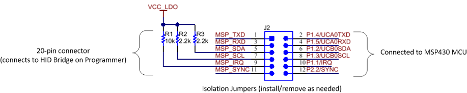
Fig. 276 Communication Isolation Jumpers
Jumper |
Description |
Alternate Use |
|---|---|---|
TXD |
MSP430FR2676 UART data out |
P1.4 |
RXD |
MSP430FR2676 UART data in |
P1.5 |
SDA |
MSP430FR2676 I2C data in/out |
P1.2 |
SCL |
MSP430FR2676 I2C clock input |
P1.3 |
IRQ |
MSP430FR2676 I2C slave Interrupt out |
P1.1 |
SYNC |
MSP430FR2676 CapTIvate Sync input |
P2.2 |
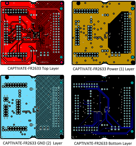
Schematics
CAPTIVATE-FR2676 Design files are available for download., visit the CAPTIVATE-FR2676 tool folder.
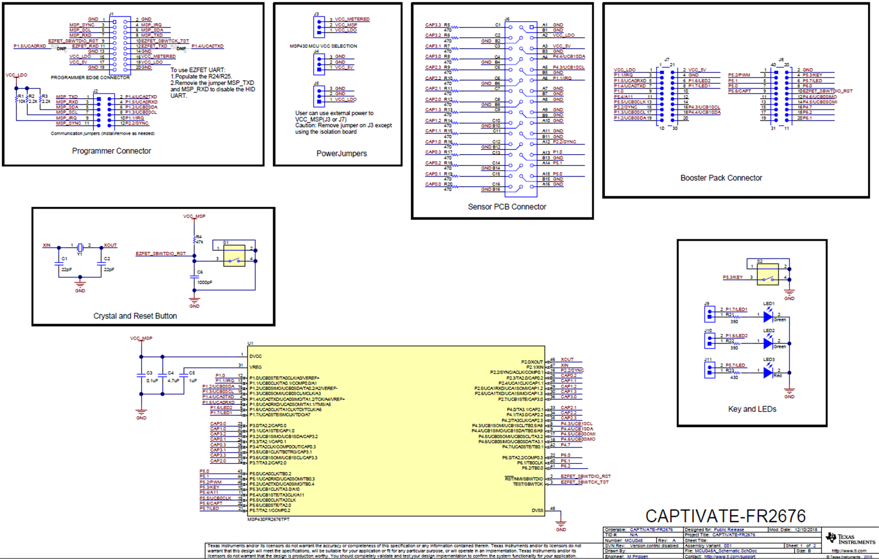
Fig. 277 CAPTIVATE-FR2676 Schematic