- Note
- Refer to EVM page for more details on the EVM, https://www.ti.com/tool/TMDS64GPEVM
Refer to SK page for more details on the AM64X-SK, https://www.ti.com/tool/SK-AM64
- Attention
- This document contains the details for AM64X-EVM and AM64X-SK board setup under each section. User should select the right board setup in the sections.
Cable Connections
AM64X-EVM
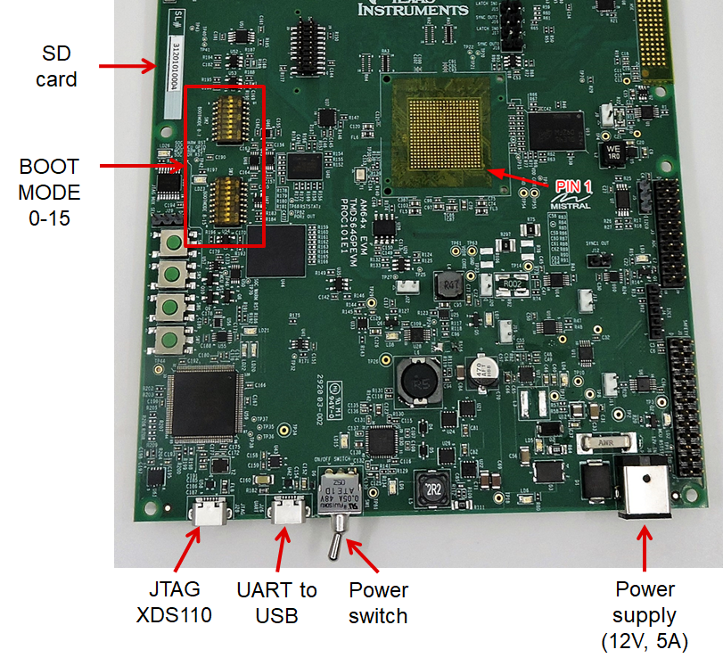
- The figure below shows some important cable connections, ports and switches.
- Take note of the location of the "BOOTMODE" switch, this is used to switch between different boot modes like OSPI, UART, SD, NOBOOT mode
AM64X-EVM
AM64X-SK
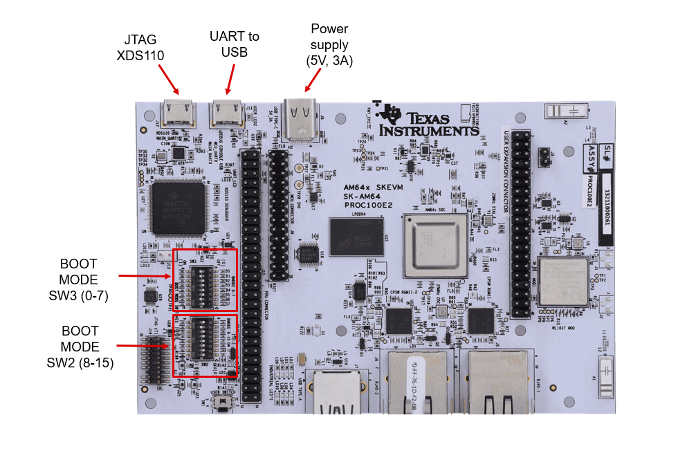
- The figure below shows some important cable connections, ports and switches.
- Take note of the location of the "BOOTMODE" switch, this is used to switch between different boot modes like OSPI, UART, SD, NOBOOT mode
AM64X-SK
Device Type Identification
- The MCU+SDK supports two device types: HS-FS (High Security - Field Securable) and GP (General Purpose). The HS-FS is the main device type and the support for GP device is deprecated. Please use SoC ID parser Python Script to identify the device type.
- Note
- It is recommended to know the device type before loading or flashing the binary into the target.
Setup UART Terminal
AM64X-EVM
- Many examples use a standard UART terminal to log the output from the examples. You can use any UART terminal program for the same. Below steps show how to setup the UART terminal from CCS.
- First identify the UART port as enumerated on the host machine.
- Make sure that the EVM and UART cable connected as shown in Cable Connections
- In windows, you can use the "Device Manager" to see the detected UART ports
- Search "Device Manager" in Windows Search Box in the Windows taskbar.
- If dont see any USB serial ports listed in "Device Manager" under "Ports (COM & LPT)", then make sure you have installed the UART to USB driver from FTDI, https://www.ftdichip.com/FTDrivers.htm.
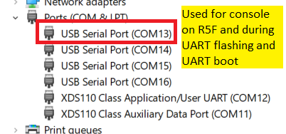
Identify UART Port in Windows Device Manager
- In CCS, goto "View > Terminal"
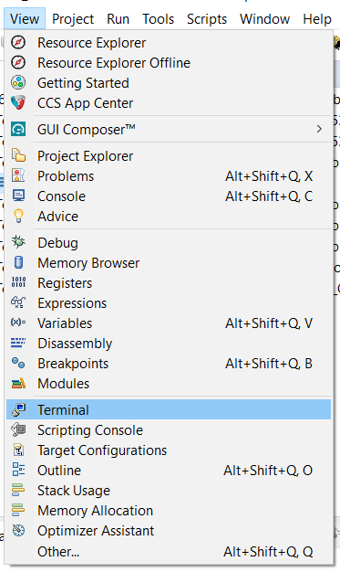
UART Terminal Menu
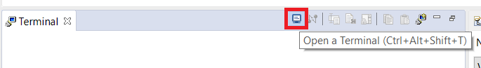
Open New UART Terminal
- Select the UART port, keep other options to default, i.e 115200 baud rate - 8 data bits - No parity - 1 stop bit,
- We use the 1st USB serial port, as seen in the device manager, for below in the SDK
- Flashing application via UART
- Booting application via UART
- Console output for examples which run from R5F
- We use the 2nd USB serial port, as seen in the device manager, as terminal output for examples which run from M4F
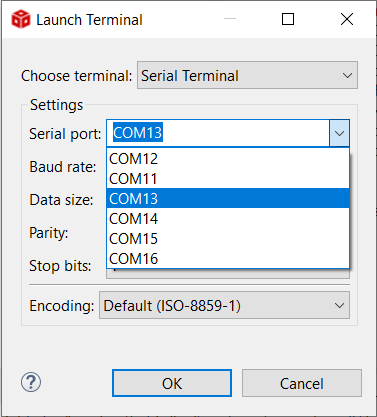
Connect to UART port
- In this screenshot this happens to be COM13 and COM14 however on your machine this could be different. One tip to make sure there is no mistake in identifying the UART port is to disconnect all other UART to USB devices other than this EVM before checking in device manager.
AM64X-SK
- Many examples use a standard UART terminal to log the output from the examples. You can use any UART terminal program for the same. Below steps show how to setup the UART terminal from CCS.
- First identify the UART port as enumerated on the host machine.
- Make sure that the AM64X-SK and UART cable connected as shown in Cable Connections
- In windows, you can use the "Device Manager" to see the detected UART ports
- Search "Device Manager" in Windows Search Box in the Windows taskbar.
- If dont see any USB serial ports listed in "Device Manager" under "Ports (COM & LPT)", then make sure you have installed the UART to USB driver from Silicon labs,https://www.silabs.com/developers/usb-to-uart-bridge-vcp-drivers.
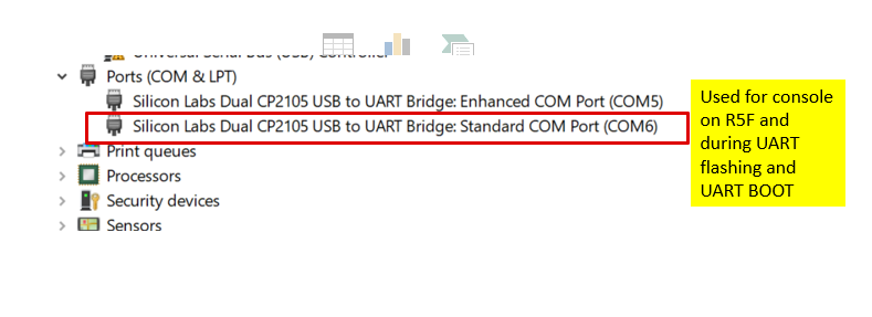
Identify UART Port in Windows Device Manager
- In CCS, goto "View > Terminal"
UART Terminal Menu
Open New UART Terminal
- Select the UART port, keep other options to default, i.e 115200 baud rate - 8 data bits - No parity - 1 stop bit,
- We use the 2nd USB serial port, as seen in the device manager, for below in the SDK
- Flashing application via UART
- Booting application via UART
- Console output for examples which run from R5F
- We use the 1st USB serial port, as seen in the device manager, as terminal output for examples which run from M4F
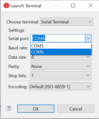
Connect to UART port
- In this screenshot this happens to be COM5 and COM6 however on your machine this could be different. One tip to make sure there is no mistake in identifying the UART port is to disconnect all other UART to USB devices other than this AM64X-SK before checking in device manager.
Flash SOC Initialization Binary
AM64X-EVM
- Attention
- This is a recommended one time step that needs to be done before you can load and run programs via CCS
-
If this step fails, maybe due to bad flash in EVM, then try one of the other SOC initialization steps mentioned at SOC Initialization
-
This step needs to be done once unless the OSPI flash has been erased or some other application has been flashed
- A quick recap of steps done so far that are needed for the flashing to work
- Make sure the UART port used for terminal is identified as mentioned in Setup UART Terminal
- Make sure python3 is installed as mentioned in Python3
- Make sure you have the EVM power cable and UART cable connected as shown in Cable Connections
- POWER-OFF the EVM
- Set boot mode to UART BOOTMODE as shown in below image
UART BOOT MODE
- POWER-ON the EVM
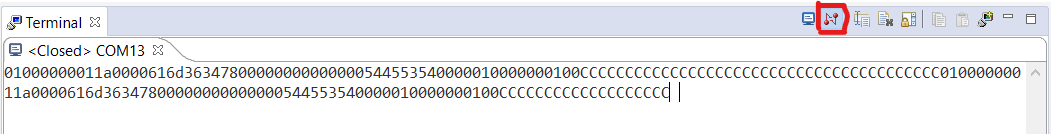
- You should see character "C" getting printed on the UART terminal every 2-3 seconds as shown below

UART output in UART BOOT MODE
- Close the UART terminal as shown below. This is important, else the UART script in next step wont be able to connect to the UART port.
Close UART terminal
- Open a command prompt and run the below command to flash the SOC initialization binary to the EVM.
  cd ${SDK_INSTALL_PATH}/tools/boot
  python uart_uniflash.py -p COM<x> --cfg=sbl_prebuilt/am64x-evm/default_sbl_null.cfg
- Here COM<x> is the port name of the identified UART port in Windows.
- On Linux,
- The name for UART port is typically something like
/dev/ttyUSB0
- On some Linux systems, one needs to use
python3 to invoke python3.x, just python command may invoke python 2.x which will not work with the flashing script.
- When the flashing is in progress you will see something like below
  C:\ti\mcu_plus_sdk_am64x_09_00_00_00\tools\boot>python uart_uniflash.py -p COM13 --cfg=sbl_prebuilt\am64x-evm\default_sbl_null.cfg

  Parsing config file ...
  Parsing config file ... SUCCESS. Found 2 command(s) !

  Executing command 1 of 2 ...
  Found flash writer ... sending sbl prebuilt/am64x-evm/sbl_uart_uniflash.hs_fs.tiimage
  Sending sbl_prebuilt/am64x-evm/sbl_uart_uniflash.release.hs_fs.tiimage: 24% ||||   | 58653/244220 [00:07<00:17, 10706.64bytes/s],
- After all the flashing is done, you will see something like below
  Parsing config file ...
  Parsing config file ... SUCCESS. Found 2 command(s) !

  Executing command 1 of 2 ...
  Found flash writer ... sending sbl_prebuilt/am64x-evm/sbl_uart_uniflash.release.hs_fs.tiimage
  Sent flashwriter sbl_prebuilt/am64x-evm/sbl_uart_uniflash.release.hs_fs.tiimage of size 244220 bytes in 24.84s.

  Executing command 2 of 2
  Command arguments : -—file=sbl _prebuilt/am64x-evm/sbl null.release.hs_fs.tiimage --operation=flash --flash-offset=0x0
  Sent sbl_prebuilt/am64x-evm/sbl_null.release.hs_fs.tiimage of size 231036 bytes in 24.06s.

  [STATUS] SUCCESS

  All commands from config file are executed !
- If flashing has failed, see Flash tool error messages and solutions, and resolve the errors.
- If flashing is successful, do the next steps ...
- POWER-OFF the EVM
- Switch the EVM boot mode to OSPI mode as shown below,
OSPI BOOT MODE
- Re-connect the UART terminal in CCS window as shown in Setup UART Terminal
- POWER-ON the EVM
- You should see output like below on the UART terminal
  Starting NULL Bootloader ...

  DMSC Firmware Version 21.1.1--v2021.01a (Terrific Lla
  DMSC Firmware revision 0x15
  DMSC ABI revision 3.1

  INFO: Bootloader_runCpu:151: CPU r5f1-0  is initialized to 800000000 Hz !!!
  INFO: Bootloader_runCpu:151: CPU r5f1-1 is initialized to 800000000 Hz !!!
  INFO: Bootloader_runCpu:151: CPU m4f0-0 is initialized to 400000000 Hz !!!
  INFO: Bootloader_loadSelfCpu:203: CPU r5f0-0 is initialized to 800000000 Hz !!!
  INFO: Bootloader_loadSelfCpu:203: CPU r5f0-1 is initialized to 800000000 Hz !!!
  INFO: Bootloader_runSelfCpu:215: All done, reseting self ...
- Congratulations now the EVM is setup for loading and running from CCS !!!
- You dont need to do these steps again unless you have flashed some other binary to the flash.
- Now you can build a example of interest (see Build a Hello World example) and then run it (see CCS Launch, Load and Run)
- Attention
- If SBL NULL is used for development, GEL files aren't required for R5FSS0-0 and A53SS0-0 they can be replaced by GELs of other R5/A53 cores. Steps are given below
- In the CCS target configuration CCXML file, under Advanced tab, select,
MAIN_Cortex_R5_0_0.
- Under Cpu Properties, there should be an option Initialization script which should have a value
../../emulation/gel/AM64x/AM64_DDRSS/AM64_GP_EVM.gel
- Click on browse and select the CPU reset gel, which should be under
<CCS_DIR>/ccs/ccs_base/emulation/gel/AM64x/CPU_reset.gel
- And for A53SS0-0. In the CCS target configuration CCXML file, under Advanced tab, select,
ComputeCluster_A53_0.
- Under Cpu Properties, there should be an option Initialization script which should have a value
../../emulation/gel/AM64x/AM64_DDRSS/AM64_GP_EVM.gel
- This field needs to be cleared for
ComputeCluster_A53_0 when using SBL NULL
- Save the target configuration file.
AM64X-SK
- Attention
- This is a recommended one time step that needs to be done before you can load and run programs via CCS
-
If this step fails, maybe due to bad flash in AM64X-SK, then try one of the other SOC initialization steps mentioned at SOC Initialization
-
This step needs to be done once unless the OSPI flash has been erased or some other application has been flashed
- A quick recap of steps done so far that are needed for the flashing to work
- Make sure the UART port used for terminal is identified as mentioned in Setup UART Terminal
- Make sure python3 is installed as mentioned in Python3
- Make sure you have the EVM power cable and UART cable connected as shown in Cable Connections
- POWER-OFF the AM64X-SK
- Set boot mode to UART BOOTMODE as shown in below image
UART BOOT MODE
- POWER-ON the EVM
- You should see character "C" getting printed on the UART terminal every 2-3 seconds as shown below
UART output in UART BOOT MODE
- Close the UART terminal as shown below. This is important, else the UART script in next step wont be able to connect to the UART port.
Close UART terminal
- Open a command prompt and run the below command to flash the SOC initialization binary to the SK.
  cd ${SDK_INSTALL_PATH}/tools/boot
  python uart_uniflash.py -p COM<x> --cfg=sbl_prebuilt/am64x-sk/default_sbl_null.cfg
- Here COM<x> is the port name of the identified UART port in Windows.
- On Linux,
- The name for UART port is typically something like
/dev/ttyUSB0
- On some Linux systems, one needs to use
python3 to invoke python3.x, just python command may invoke python 2.x which will not work with the flashing script.
- When the flashing is in progress you will see something like below
  C:\ti\mcu_plus_sdk_am64x_09_00_00_00\tools\boot>python uart_uniflash.py -p COM13 --cfg=sbl_prebuilt\am64x-sk\default_sbl_null.cfg

  Parsing config file ...
  Parsing config file ... SUCCESS. Found 2 command(s) !

  Executing command 1 of 2 ...
  Found flash writer ... sending sbl prebuilt/am64x-sk/sbl_uart_uniflash.hs_fs.tiimage
  Sending sbl_prebuilt/am64x-sk/sbl_uart_uniflash.release.hs_fs.tiimage: 24% ||||   | 58653/244220 [00:07<00:17, 10706.64bytes/s],
- After all the flashing is done, you will see something like below
  Parsing config file ...
  Parsing config file ... SUCCESS. Found 2 command(s) !

  Executing command 1 of 2 ...
  Found flash writer ... sending sbl_prebuilt/am64x-sk/sbl_uart_uniflash.release.hs_fs.tiimage
  Sent flashwriter sbl_prebuilt/am64x-sk/sbl_uart_uniflash.release.hs_fs.tiimage of size 244220 bytes in 24.84s.

  Executing command 2 of 2
  Command arguments : -—file=sbl _prebuilt/am64x-sk/sbl null.release.hs_fs.tiimage --operation=flash --flash-offset=0x0
  Sent sbl_prebuilt/am64x-sk/sbl_null.release.hs_fs.tiimage of size 231036 bytes in 24.06s.

  [STATUS] SUCCESS

  All commands from config file are executed !
- If flashing has failed, see Flash tool error messages and solutions, and resolve the errors.
- If flashing is successful, do the next steps ...
- POWER-OFF the AM64X-SK
- Switch the SK boot mode to OSPI mode as shown below,
OSPI BOOT MODE
- Re-connect the UART terminal in CCS window as shown in Setup UART Terminal
- POWER-ON the AM64X-SK
- You should see output like below on the UART terminal
  Starting NULL Bootloader ...

  DMSC Firmware Version 22.1.1--v2022.01 (Terrific Llam
  DMSC Firmware revision 0x16
  DMSC ABI revision 3.1

  INFO: Bootloader_runCpu:150: CPU r5f1-0  is initialized to 800000000 Hz !!!
  INFO: Bootloader_runCpu:150: CPU r5f1-1 is initialized to 800000000 Hz !!!
  INFO: Bootloader_runCpu:150: CPU m4f0-0 is initialized to 400000000 Hz !!!
  INFO: Bootloader_runCpu:150: CPU a530-0 is initialized to 800000000 Hz !!!
  INFO: Bootloader_runCpu:150: CPU a530-1 is initialized to 800000000 Hz !!!
  INFO: Bootloader_loadSelfCpu:202: CPU r5f0-0 is initialized to 800000000 Hz !!!
  INFO: Bootloader_loadSelfCpu:202: CPU r5f0-1 is initialized to 800000000 Hz !!!
  INFO: Bootloader_runSelfCpu:219: All done, reseting self ...
- Congratulations now the AM64X-SK is setup for loading and running from CCS !!!
- You dont need to do these steps again unless you have flashed some other binary to the flash.
- Now you can build a example of interest (see Build a Hello World example) and then run it (see CCS Launch, Load and Run)
- Attention
- If SBL NULL is used for development, GEL files aren't required for R5FSS0-0 and A53SS0-0 they can be replaced by GELs of other R5/A53 cores. Steps are given below
- In the CCS target configuration CCXML file, under Advanced tab, select,
MAIN_Cortex_R5_0_0.
- Under Cpu Properties, there should be an option Initialization script which should have a value
../../emulation/gel/AM64x/AM64_DDRSS/AM64_SK_EVM.gel
- Click on browse and select the CPU reset gel, which should be under
<CCS_DIR>/ccs/ccs_base/emulation/gel/AM64x/CPU_reset.gel
- And for A53SS0-0. In the CCS target configuration CCXML file, under Advanced tab, select,
ComputeCluster_A53_0.
- Under Cpu Properties, there should be an option Initialization script which should have a value
../../emulation/gel/AM64x/AM64_DDRSS/AM64_SK_EVM.gel
- This field needs to be cleared for
ComputeCluster_A53_0 when using SBL NULL
- Save the target configuration file.
Additional Details
- Note
- This section has more details on AM64X-EVM. This is mainly for reference and can be skiped unless referred to by other pages in this user guide.
SOC Initialization
Before any program can be loaded and run on the EVM, the SOC needs to be initialized. Below sections describes the various options available for SOC initialization.
It is recommended to use the method mentioned in Flash SOC Initialization Binary. However in some cases, additional methods described below can be used esp when running on your own custom EVM and flash driver is not yet available for that EVM.
SOC Initialization Using SD BOOT
AM64X-EVM
- Note
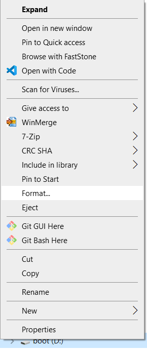
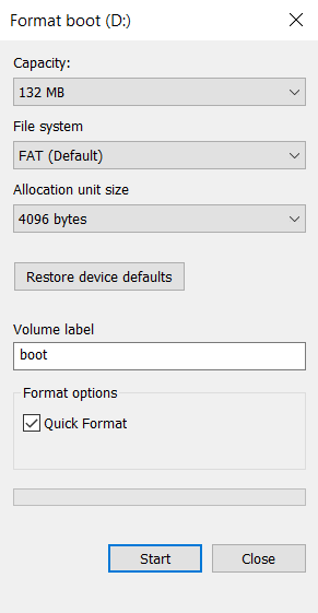
- This step needs to be done once, unless the SD card is reformatted and/or the boot file is changed
SD BOOT MODE
- Insert the formated SD card in the SD card slot in the EVM
- Open a UART terminal as mentioned in Setup UART Terminal
- POWER-ON the EVM
- You should see output like below on the UART terminal
  Starting NULL Bootloader ...

  DMSC Firmware Version 21.1.1--v2021.01a (Terrific Lla
  DMSC Firmware revision 0x15
  DMSC ABI revision 3.1

  INFO: Bootloader_runCpu:151: CPU r5f1-0  is initialized to 800000000 Hz !!!
  INFO: Bootloader_runCpu:151: CPU r5f1-1 is initialized to 800000000 Hz !!!
  INFO: Bootloader_runCpu:151: CPU m4f0-0 is initialized to 400000000 Hz !!!
  INFO: Bootloader_loadSelfCpu:203: CPU r5f0-0 is initialized to 800000000 Hz !!!
  INFO: Bootloader_loadSelfCpu:203: CPU r5f0-1 is initialized to 800000000 Hz !!!
  INFO: Bootloader_runSelfCpu:215: All done, reseting self ...
- Congratulations now the EVM is setup for loading and running from CCS !!!
- You dont need to do these steps again unless you have changed or re-formatted or deleted/changed the
tiboot3.bin file.
AM64X-SK
- Note
- This step needs to be done once, unless the SD card is reformatted and/or the boot file is changed
SD BOOT MODE
- Insert the formated SD card in the SD card slot in the EVM
- Open a UART terminal as mentioned in Setup UART Terminal
- POWER-ON the AM64X-SK
- You should see output like below on the UART terminal
  Starting NULL Bootloader ...

  DMSC Firmware Version 22.1.1--v2022.01 (Terrific Llam
  DMSC Firmware revision 0x16
  DMSC ABI revision 3.1

  INFO: Bootloader_runCpu:150: CPU r5f1-0  is initialized to 800000000 Hz !!!
  INFO: Bootloader_runCpu:150: CPU r5f1-1 is initialized to 800000000 Hz !!!
  INFO: Bootloader_runCpu:150: CPU m4f0-0 is initialized to 400000000 Hz !!!
  INFO: Bootloader_runCpu:150: CPU a530-0 is initialized to 800000000 Hz !!!
  INFO: Bootloader_runCpu:150: CPU a530-1 is initialized to 800000000 Hz !!!
  INFO: Bootloader_loadSelfCpu:202: CPU r5f0-0 is initialized to 800000000 Hz !!!
  INFO: Bootloader_loadSelfCpu:202: CPU r5f0-1 is initialized to 800000000 Hz !!!
  INFO: Bootloader_runSelfCpu:219: All done, reseting self ...
- Congratulations now the EVM is setup for loading and running from CCS !!!
- You dont need to do these steps again unless you have changed or re-formatted or deleted/changed the
tiboot3.bin file.
SOC Initialization Using CCS Scripting
Set Environment Variable
- Note
- This step needs to be done once and is needed for the SOC initialization script
load_dmsc_hsfs.js to find certain initialization files within the SDK folder. This variable is not used otherwise in the build process. If you dont like adding variables in the environment, then you need to edit the file ${SDK_INSTALL_PATH}/tools/ccs_load/am64x/load_dmsc_hsfs.js and specify the SDK path in the file itself.
- Add path to the SDK folder as a environment variable in the host machine.
- In windows, goto "Windows Task Bar Search" and search for "environment variables for your account"
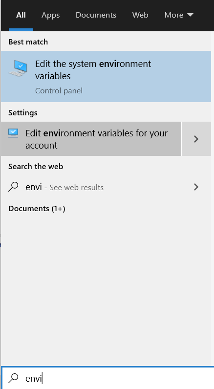
Environment Variables For Your Account
- Add a new variable named
MCU_PLUS_SDK_AM64X_PATH and point it to the path where the SDK is installed
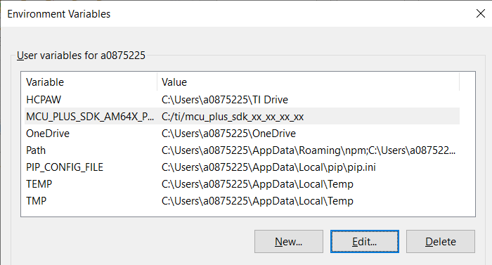
Add New Environment Variable For Your Account
- In Linux, usually you need to add a line as below in the ${HOME}/.bashrc,
export MCU_PLUS_SDK_AM64X_PATH=${HOME}/ti/mcu_plus_sdk_am64x_{sdk version}/
- If CCS is open, close and reopen CCS for the CCS to be able to see the updated environment variable
Run the SOC Initialization Script
AM64X-EVM
- Attention
- This step needs to be done every time the EVM is power-cycled.
- POWER-OFF the EVM
- Make sure below cables are connected as shown in Cable Connections
- Set EVM in DEV BOOT MODE mode as shown below
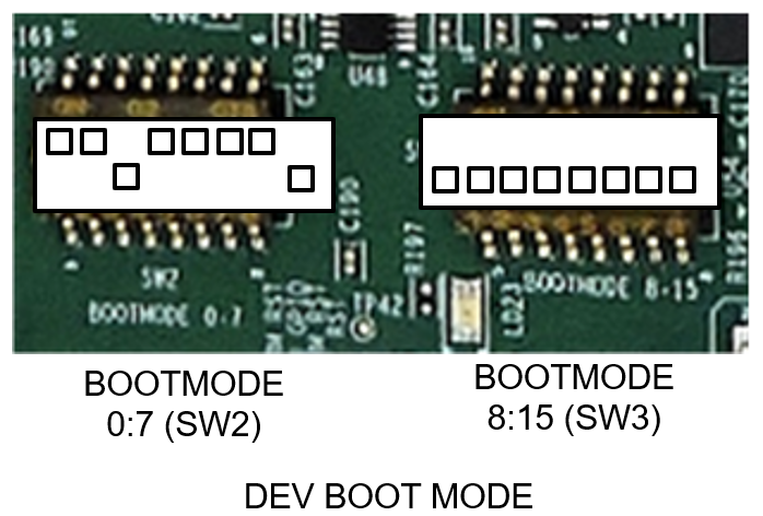
DEV BOOT MODE
- POWER-ON the EVM
- Launch the target configuration created with Create Target Configuration
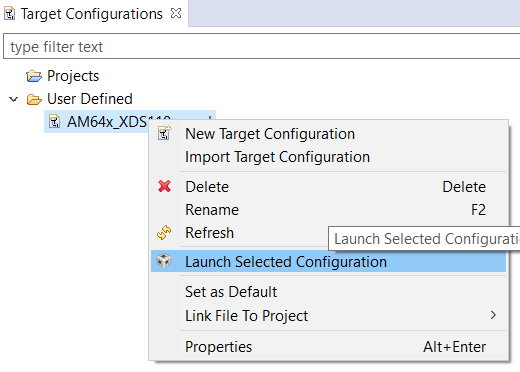
Launch Target Configuration
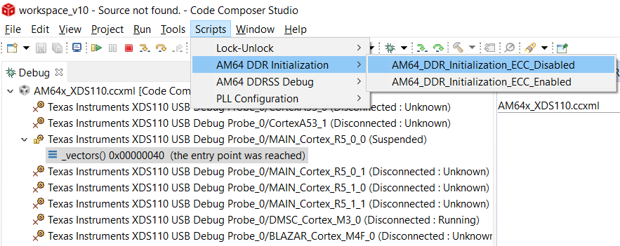
- You will see the AM64X target configuration in the "Debug" window as shown below
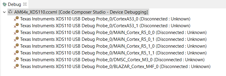
Target Configuration After Launch
- Goto "CCS Toolbar > View > Scripting Console"
- Type the below command in the scripting console and press "enter", to load DMSC FW and initialize the SOC
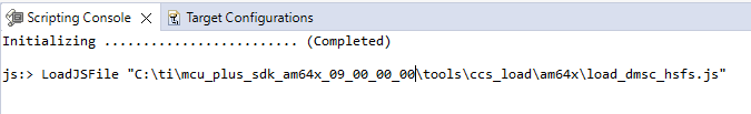
Scripting Console
- In Linux, run the same command, only the path would be a Linux path like
/home/{username}/ti/mcu_plus_sdk_{soc}_{sdk version}/tools/ccs_load/am64x/load_dmsc_hsfs.js
- After successful execution of this script one would see logs as below
- In the scripting console, this is log from the script itself.
js:> LoadJSFile "C:/ti/mcu_plus_sdk/tools/ccs_load/am64x/load_dmsc_hsfs.js"
Connecting to MCU Cortex_R5_0!
Writing While(1) for R5F
Running the board configuration initialization from R5!
Happy Debugging
- In the AM64X "CIO" console, this is log from the R5F.
[MAIN_Cortex_R5_0_0]
DMSC Firmware Version 10.0.8--v10.00.08 (Fiery Fox)
DMSC Firmware revision 0xa
DMSC ABI revision 4.0

[SCICLIENT] ABI check PASSED
[SCICLIENT] Board Configuration with Debug enabled ...
[SCICLIENT] Common Board Configuration PASSED
[SCICLIENT] PM Board Configuration PASSED
[SCICLIENT] RM Board Configuration PASSED
[SCICLIENT] Security Board Configuration PASSED

DMSC Firmware Version 10.0.8--v10.00.08 (Fiery Fox)
DMSC Firmware revision 0xa
DMSC ABI revision 4.0

Starting SOC Initialization ...
Resetting self cluster ...
- In the AM64X console, this is log from the GEL scripts.

Select AM64X GEL Console
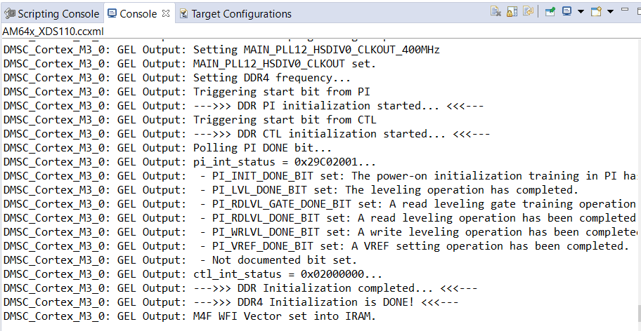
AM64X Console GEL Log
- For success, all the three consoles should have no errors in their logs.
- If the script is run without providing power to the EVM or if the EVM BOOTMODE is not set to DEV BOOT MODE then you will see errors in the console and/or unexpected behaviour and error messages.
- SOLUTION: Power cycle EVM and repeat the steps.
AM64X-SK
- Attention
- This step needs to be done every time the EVM is power-cycled.
- POWER-OFF the AM64X-SK
- Make sure below cables are connected as shown in Cable Connections
- Set EVM in NOBOOT mode as shown below
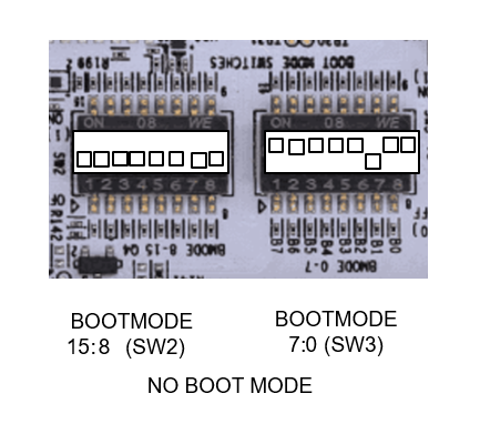
NO BOOT MODE
- POWER-ON the AM64X-SK
- Launch the target configuration created with Create Target Configuration
Launch Target Configuration
- You will see the AM64X target configuration in the "Debug" window as shown below
Target Configuration After Launch
- Goto "CCS Toolbar > View > Scripting Console"
- Type the below command in the scripting console and press "enter", to load DMSC FW and initialize the SOC
Scripting Console
- In Linux, run the same command, only the path would be a Linux path like
/home/{username}/ti/mcu_plus_sdk_{soc}_{sdk version}/tools/ccs_load/am64x/load_dmsc_hsfs.js
- After successful execution of this script one would see logs as below
- In the scripting console, this is log from the script itself.
js:> LoadJSFile "C:/ti/mcu_plus_sdk/tools/ccs_load/am243x/load_dmsc_hsfs.js"
Connecting to MCU Cortex_R5_0!
Writing While(1) for R5F
Running the board configuration initialization from R5!
Happy Debugging
- In the AM64X "CIO" console, this is log from the R5F.
[MAIN_Cortex_R5_0_0]
DMSC Firmware Version AA.B.C-vDDDD.EEE-FF-gggggg (HHH
DMSC Firmware revision 0xNN
DMSC ABI revision x.y

[SCICLIENT] ABI check PASSED
[SCICLIENT] Board Configuration with Debug enabled ...
[SCICLIENT] Common Board Configuration PASSED
[SCICLIENT] PM Board Configuration PASSED
[SCICLIENT] RM Board Configuration PASSED
[SCICLIENT] Security Board Configuration PASSED

DMSC Firmware Version AA.B.C-vDDDD.EEE-FF-gggggg (HHH
DMSC Firmware revision 0xNN
DMSC ABI revision x.y

All tests have passed!!
- In the AM64X console, this is log from the GEL scripts.
Select AM64X GEL Console
AM64X Console GEL Log
- For success, all the three consoles should have no errors in their logs.
- If the script is run without providing power to the AM64X-SK or if the AM64X-SK BOOTMODE is not set to DEV BOOT MODE then you will see errors in the console and/or unexpected behaviour and error messages.
- SOLUTION: Power cycle AM64X-SK and repeat the steps.
DDR Initialization
- To initialize DDR, do the additional step below from CCS GEL menu.
- Launch CCS debug session as mentioned here, Launch CCS
- Connect to
MAIN_Cortex_R5_0_0

Connect to R5F0-0
- Run the DDR initialization from GEL menu as shown below,
DDR initialization via GEL menu
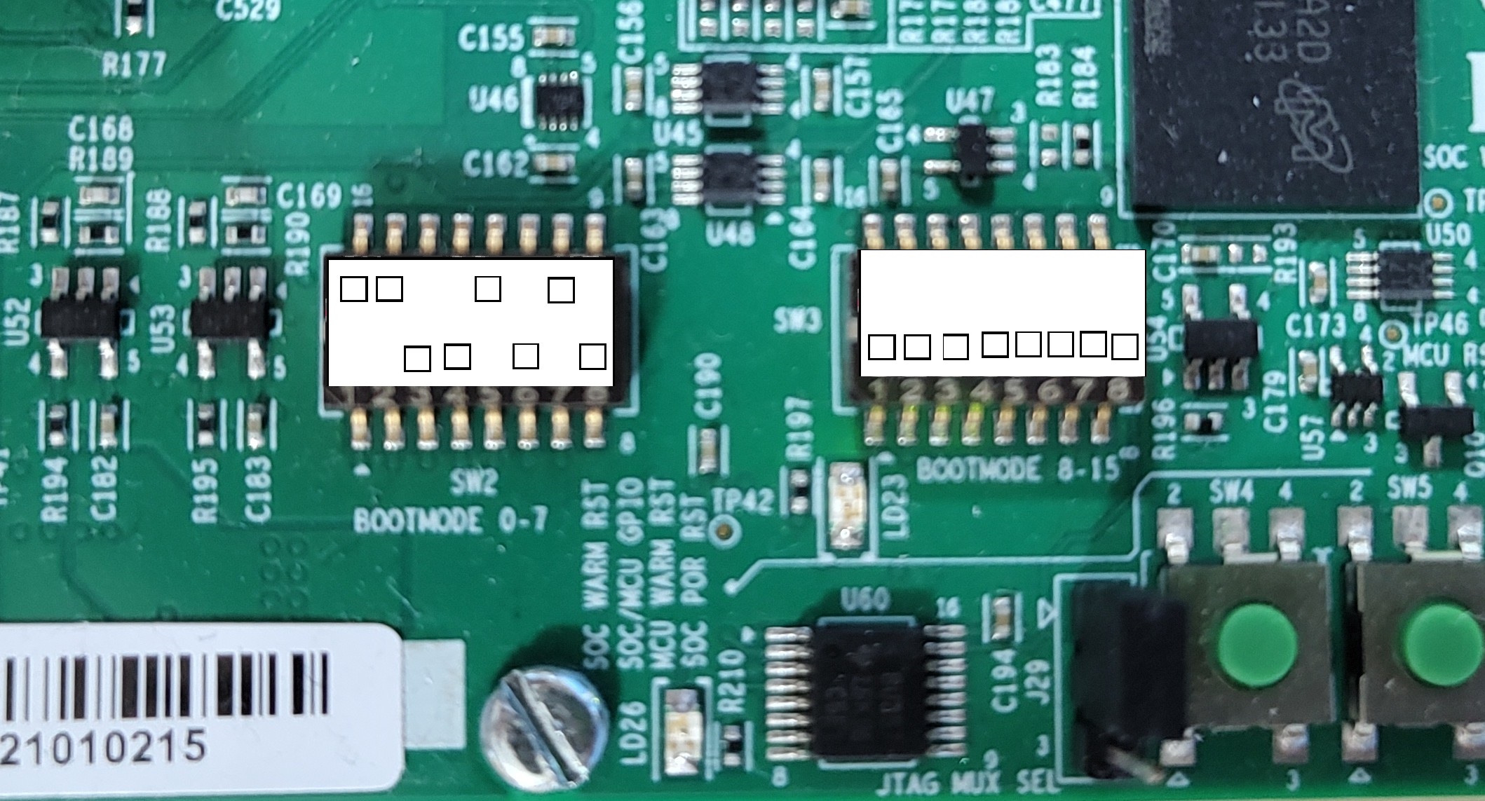
BOOT MODE
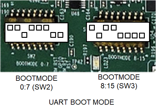
UART BOOT MODE
AM64X-EVM
This mode is used to flash files to the EVM flash via UART. It can also be used to boot applications via UART.
BOOTMODE [ 0 : 7 ] (SW2) = 1101 1100
BOOTMODE [ 8 : 15 ] (SW3) = 1011 0000
UART BOOT MODE
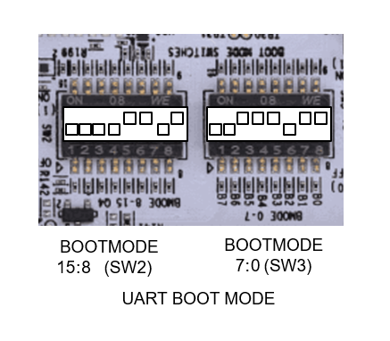
AM64X-SK
This mode is used to flash files to the AM64X-SK flash via UART. It can also be used to boot applications via UART.
BOOTMODE [ 15 : 8 ] (SW2) = 0000 1101
BOOTMODE [ 7 : 0 ] (SW3) = 0011 1011
UART BOOT MODE
DFU BOOT MODE
AM64x-EVM
This mode is used to flash files to the EVM flash via USB2.0 DFU. It can also be used to boot applications via USB2.0 DFU.
\code
BOOTMODE [ 0 :  7 ] (SW2) = 1100 1010
BOOTMODE [ 8 : 15 ] (SW3) = 0000 0000
\endcode
DFU BOOT MODE
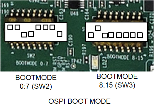
OSPI BOOT MODE
AM64X-EVM
This mode is used to boot flashed applications via EVM flash like OSPI flash
BOOTMODE [ 0 : 7 ] (SW2) = 1100 1110
BOOTMODE [ 8 : 15 ] (SW3) = 0100 0000
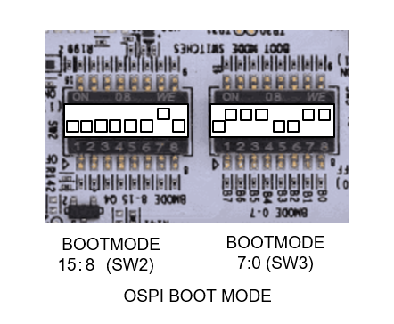
OSPI BOOT MODE
AM64X-SK
This mode is used to boot flashed applications via AM64X-SK flash like OSPI flash
BOOTMODE [ 15 : 8 ] (SW2) = 0000 0010
BOOTMODE [ 7 : 0 ] (SW3) = 0111 0011
OSPI BOOT MODE
SD BOOT MODE
AM64X-EVM
This mode is used to boot applications via SD card on the EVM.
BOOTMODE [ 0 : 7 ] (SW2) = 1100 0011
BOOTMODE [ 8 : 15 ] (SW3) = 0110 1100
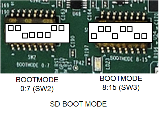
SD BOOT MODE
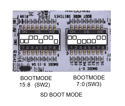
AM64X-SK
This mode is used to boot applications via SD card on the AM64X-SK.
BOOTMODE [ 15 : 8 ] (SW2) = 0011 0110
BOOTMODE [ 7 : 0 ] (SW3) = 1100 0011
SD BOOT MODE
DEV BOOT MODE
AM64X-EVM
This mode is used in conjunction with the load_dmsc_hsfs.js script described here SOC Initialization Using CCS Scripting,
BOOTMODE [ 0 : 7 ] (SW2) = 1101 1110
BOOTMODE [ 8 : 15 ] (SW3) = 0000 0000
DEV BOOT MODE
AM64X-SK
This mode is used in conjunction with the load_dmsc.js script described here SOC Initialization Using CCS Scripting,
BOOTMODE [ 0 : 7 ] (SW2) = 0000 0000
BOOTMODE [ 8 : 15 ] (SW3) = 1111 1011
NO BOOT MODE
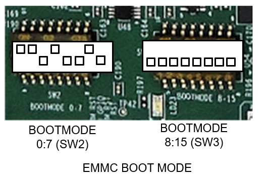
EMMC BOOT MODE
AM64X-EVM
This mode is used to boot applications via eMMC on the EVM.
BOOTMODE [ 0 : 7 ] (SW2) = 1101 0010
BOOTMODE [ 8 : 15 ] (SW3) = 0000 0000
EMMC BOOT MODE
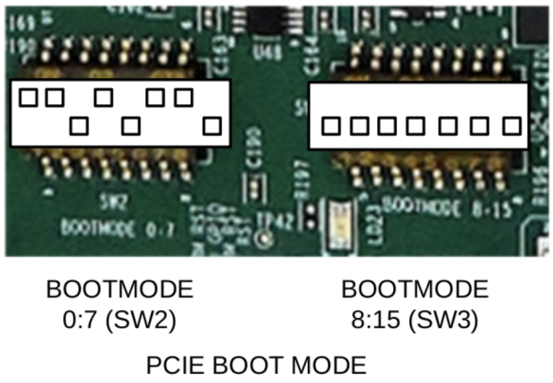
PCIE BOOT MODE
AM64X-EVM
This mode is used to boot applications via PCIe on the EVM.
BOOTMODE [ 0 : 7 ] (SW2) = 1101 0110
BOOTMODE [ 8 : 15 ] (SW3) = 0000 0000
PCIE BOOT MODE
Troubleshooting EVM issues
- JTAG connection fails on some EVMs with the following error. Need to connect the JTAG cable after board is powered on.
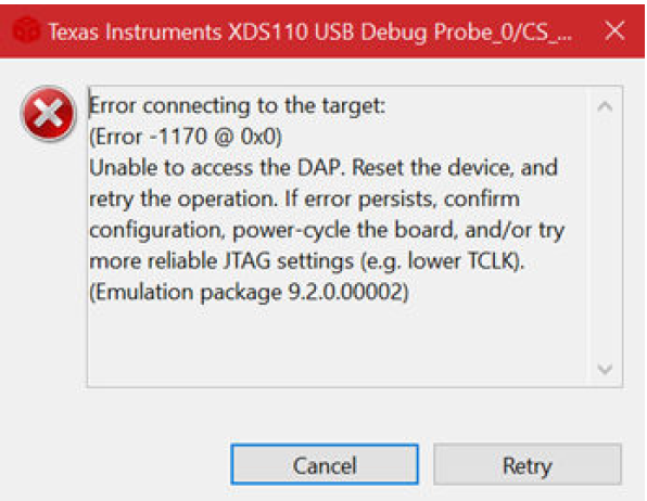
JTAG Connection Error Dialog
 1.8.20