LE Coded PHY
Introduction
The physical layer (PHY) is the lowest layer of the Bluetooth low energy protocol stack. It configures the physical parameters of the radio transmission and reception. It determines how a bit (and its value) are represented over the air.
By switching the PHY, the physical properties of the RF signal is changed. In the case of the LE Coded PHY, the signal range will be nearly quadrupled compared to the LE 1M PHY. This is achieved by coding the signal, so the Tx power stays the same. This means that the power consumption per time stays the same. On the other hand, this coding entails a lower data throughput.
Link Budget
The LE Coded PHY gives a higher sensitivity than the LE 1M PHY. The receiver sensitivity is defined by how weak signals the receiver can receive compared to the level of interfering RF power received simultaneously. If no interference is present, the sensitivity level is determined by the thermal background noise and will correspond to the sensitivity specified in the datasheet.
In an operating RF link, the transmitter will transmit at a specified RF power level, and a (usually very tiny) fraction of that RF power will be picked up by the receiving antenna and fed to the receiver. If that fraction is too small, the received power level will drop below the receiver sensitivity level and the link will fail.
The link budget is the ratio between transmitted power and the Rx sensitivity level. For convenience, the link budget (LB) is usually denoted in a logarithmic scale (dB). Output power and sensitivity are usually denoted in a logarithmic scale relative to 1mW (dBm). This means that:

There are two ways to improve the link budget:
- Increase the output power
- Improve (reduce) the receiver sensitivity level
Increasing the output power is fairly straight forward, but it comes at the cost of (sometimes significantly) increased power consumption. In addition, all regulatory jurisdictions have limits on RF emission levels and unwanted spurious emissions, both of which will increase if the transmit power is increased.
The other option, improving receiver sensitivity, is the path chosen by the Bluetooth SIG when Bluetooth 5 was adopted with the intention of offering four times the RF range. This was also chosen to provide the longest range Bluetooth low energy solutions at lowest power consumption. In free space, a doubling of the range requires a quadrupling of the link budget (or 6dB increase). This means that four times the range requires 12 dB better sensitivity for the LE Coded PHY, when compared with the LE 1M PHY. The reference for LE 1M PHY is set to -93 dBm. (Note that -93 dBm was chosen as a reference point for a standard radio at the time the spec was written. On the CC26x2, the sensitivity is higher. You can find the sensitivity in the datasheet.) Since the reference for LE 1M PHY is -93 dBm, the LE Coded PHY needs a sensitivity of -105dBm. See Figure 44.
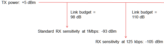
Figure 44. Link Budget Illustration
The link budget increase is achieved through a two-way approach:
- The biggest improvement comes simply from the fact that the data rate is reduced to 1/8th, which means that every bit carries eight times more energy for any given power level. Theoretically, this allows the receiver to receive signals at 9dB lower power levels and still accumulate the same energy per bit as before.
- The last 3 dB can be achieved due to the coding employed. The -93dBm comparison level (for 1Mpbs) assumed a standard differential demodulator, where each received symbol (1 symbol per bit) is determined to be “1” or “0” based on a comparison with the previous symbol. The Coded PHYs facilitate a semi-coherent receiver where eight symbols make up 1 bit, and correlators can search for these known symbol sequences. This is called Forward Error Correction (FEC).
It is worth noting that even though the Tx power is the same for LE Coded PHY as for LE 1M PHY, the data rate is lower, thus the device will spend a longer time to send the same amount of data. This will give a higher power consumption for sending the same amount of data on LE Coded PHY compared to LE 1M PHY.
You can read more about how the LE Coded PHY in this blog: How does Bluetooth® 5 increase the achievable range of a Bluetooth low energy connection?
LE Coded S2 and S8
The LE Coded PHY can be operated with two data rates:
- S2 : In LE Coded S=2 mode, each bit is represented by two symbols. Thus, the data rate is 500kbps. In this mode the range is roughly doubled compared to the LE 1M PHY.
- S8: In LE Coded S=8, each bit is represented by eight symbols. This gives a data rate of 125kbps. In this mode the range is roughly quadrupled compared to the LE 1M PHY.
Every packet sent on LE Coded PHY contains a coding indicator (CI), which indicates the coding of the packet. Thus, when a packet is being received on the LE Coded PHY, the receiver uses the coding indicator to determine the coding of the packet. The full packet format of packets sent on LE Coded PHY is found in the Bluetooth Core Specification Version 5.0, Vol 6, Part B, 2.2 PACKET FORMAT FOR THE LE CODED PHY.
PHY Comparison
The LE Coded PHY feature uses the same transmit power as the LE 1M PHY, the only change is in the modulation of data in the PHY. Using the LE Coded PHY, the energy consumption increases because the radio is in Tx longer. Thus the main application for LE Coded PHY should be applications that need a long range, but a low data rate. A comparison of the Bluetooth low energy PHYs is given below:
| Parameter | LE 1M | LE Coded S=2 | LE Coded S=8 | LE 2M |
|---|---|---|---|---|
| Symbol Rate | 1Msps | 1Msps | 1Msps | 2Msps |
| Data Rate | 1Mbps | 500kbps | 125kbps | 2Mbps |
| Error Correction | None | FEC | FEC | None |
| Range Multiplier | 1 | ~2 | ~4 | ~0.8 |
According to the Bluetooth spec, there are limitations on what packets can be sent on the LE Coded PHY. The following sections will describe how to advertise on LE Coded PHY, Scan on LE Coded PHY, and form a connection on LE Coded PHY. Changing to LE Coded PHY in a connection on LE 1M PHY will also be covered.
The following are the current PHY limitations in BLE5-Stack:
- The BLE controller does not support asymmetric connections where the connection uses different PHYs in each direction (Rx and Tx).
Advertise on LE Coded PHY
According to the Bluetooth Core Specification Version 5.0 (Version 5.0 | Vol 6, Part B, Chapter 2.3 ADVERTISING CHANNEL PDU), only the following PDU types can be transmitted on the LE Coded PHY:
- ADV_EXT_IND
- AUX_ADV_IND
- AUX_SYNC_IND
- AUX_CHAIN_IND
- AUX_SCAN_REQ
- AUX_SCAN_RSP
- AUX_CONNECT_REQ
- AUX_CONNECT_RSP
You can read about each PDU in the Bluetooth Core Specification Version 5.0, Vol 6, Part B, 2.3 ADVERTISING CHANNEL PDU.
We will use the example application simple peripheral to show how to advertise on LE Coded PHY. Please use GAP Advertiser as a reference for the advertisement API s. Set up a advertisement set as usual.
Set the primary PHY to a LE Coded PHY (GAP_ADV_PRIM_PHY_CODED_S2 or GAP_ADV_PRIM_PHY_CODED_S8) in the advertisement parameters. Alternatively you can use the predefined parameter set GAPADV_PARAMS_AE_LONG_RANGE_CONN:
// Use long range parameters to create long range adv set
GapAdv_params_t advParamLongRange = GAPADV_PARAMS_AE_LONG_RANGE_CONN;

// Alternatively, set the parameters individually.
advParamLongRange.primPhy = GAP_ADV_PRIM_PHY_CODED_S2;
advParamLongRange.secPhy = GAP_ADV_SEC_PHY_CODED_S2;

// Create Advertisement set using the parameters
status = GapAdv_create(&SimplePeripheral_advCallback, &advParamLongRange,
                       &advHandleLongRange);
The primary PHY parameter will decide whether the device is advertising in legacy mode, or in long range mode (with ADV_EXT_IND). The secondary PHY parameter will decide the PHY of any auxiliary advertisement packets (i.e. all packets beginning with AUX_).
If advertising non-connectable and non-scannable, an ADV_EXT_IND PDU with no Adv Data can be sent without an auxiliary packet. In all other cases, the ADV_EXT_IND PDU mist contain a pointer to an auxiliary advertisement packet, AUX_ADV_IND. The AUX_ADV_IND PDU is sent on the PHY given in secPhy, and on one of the secondary channels (also known as data channels).
Scan on LE Coded PHY
We will use the example application simple central to show how to scan on LE Coded PHY. Please use GAP Scanner as a reference for the scanner API s. Set up a scanner as usual.
Note
The BLE5-Stack only allows a device to scan on one PHY at the time. It is not possible to set up multiple “scanning sets”.
Setup the Scanner parameters for the LE Coded PHY
1
2
3
4
5
6
7
8
  GapScan_PrimPhy_t scanPhyLongRange = SCAN_PRIM_PHY_CODED;
  GapScan_ScanType_t scanTypeLongRange = SCAN_TYPE_ACTIVE;
  uint16_t scanIntLongRange = SCAN_PARAM_DFLT_INTERVAL;
  uint16_t scanWindowLongRange = SCAN_PARAM_DFLT_INTERVAL;

  // Set Scan PHY parameters
  GapScan_setPhyParams(scanPhyLongRange, scanTypeLongRange,
                       scanIntLongRange, scanWindowLongRange);
Set the scan PHY to LE Coded PHY.
  GapScan_PrimPhy_t scanPhyLongRange = SCAN_PRIM_PHY_CODED;

  // Set scanning primary PHY
  GapScan_setParam(SCAN_PARAM_PRIM_PHYS, &scanPhyLongRange);
As noted in LE Coded S2 and S8, each packet transmitted on the LE Coded PHY contains a coding indicator that tells the receiving device what the coding of the packet is. It is thus not necessary to tell the GAP Scanner what coding to use when scanning on the LE Coded PHY.
In order to send a scan request to an advertiser which is advertising on LE Coded PHY, the scanner must listen for the AUX_ADV_IND indicated by the pointer in the ADV_EXT_IND PDU, and send a scan request to this packet. This will be an AUX_SCAN_REQ, sent on the same PHY and channel as the AUX_ADV_IND. In turn, the advertiser can send an AUX_SCAN_RSP on the same PHY and channel.
Initiate a Connection on LE Coded PHY
We will use the example application simple central to show how to initiate a connection on LE Coded PHY. Please use GAP Initiator as a reference for the scanner API s. Set up an initiator as usual. When initiating the connection, select which PHY to use:
  GapInit_InitPhy_t initPhyLongRange = INIT_PHY_CODED;

  GapInit_connect(scanList[index].addrType & MASK_ADDRTYPE_ID,
                  scanList[index].addr, initPhyLongRange, 0);
In order to send a connection request to an advertiser which is advertising on LE Coded PHY, the initiator must listen for the AUX_ADV_IND indicated by the pointer in the ADV_EXT_IND PDU, and send a connection request to this packet. This will be an AUX_CONNECT_REQ, sent on the same PHY and channel as the AUX_ADV_IND. In turn, the advertiser can send an AUX_CONNECT_RSP on the same PHY and channel.
Default PHY
The application can call HCI_LE_SetDefaultPhyCmd() to set the default PHY preferences for both master and slave configurations inside connections. If no preference is specified or the API is never called, the stack will use all supported PHYs.
The available defines for HCI_LE_SetDefaultPhyCmd() are listed in Table 4.
| Name | Usage | Description |
|---|---|---|
| HCI_PHY_USE_PHY_PARAM | allPhys | Use Phy Param |
| HCI_PHY_USE_ANY_PHY | allPhys | Use any PHY |
| HCI_PHY_1_MBPS | txPhy and rxPhy | LE 1M PHY |
| HCI_PHY_2_MBPS | txPhy and rxPhy | LE 2M PHY |
| HCI_PHY_CODED | txPhy and rxPhy | LE Coded PHY |
The HCI_LE_SetDefaultPhyCmd() should be called before forming the connection (while the HCI_LE_SetPhyCmd() can only be called during a connection). Also note that the HCI_LE_SetDefaultPhyCmd() does not change the PHY, only the HCI_LE_SetPhyCmd() can change the PHY.
  // The device will support LE 1M PHY and LE Coded PHY.
  HCI_LE_SetDefaultPhyCmd(HCI_PHY_USE_ANY_PHY, HCI_PHY_1_MBPS | HCI_PHY_CODED,
                                               HCI_PHY_1_MBPS | HCI_PHY_CODED);
Changing PHY
The application can initiate a PHY Update Procedure in a connection regardless of the role of the device (master or slave). The PHY preferences that are set by HCI_LE_SetDefaultPhyCmd() are used by default during a set PHY negotiation.
Attention
Calling HCI_LE_SetPhyCmd() to change the PHY will change the preferred PHY of the device. This means that in some cases, only the the device that first changed the active PHY can change it back.
When the application has finished the PHY critical operations, it is therefore a good idea to change the PHY to a bit mask with every supported PHY, e.g. (LE 1M PHY | LE Coded PHY). This will allow the peer device to change the PHY back to LE 1M.
The HCI_LE_SetDefaultPhyCmd() is used to specify the preferred PHY for transmit and receive for all subsequent connections. However, when the HCI_LE_SetPhyCmd() is used to change the PHY for the connection, the change only applies to that connection. Subsequent connections will revert to using the default PHYs.
The parameters for HCI_LE_SetDefaultPhyCmd() and HCI_LE_SetPhyCmd() are same. The allPhys parameter specifies whether the other two parameters (txPhy and rxPhy) are used or not. Master value of ‘1’ indicates the client has no PHY preference for that direction, while a ‘0’ indicates that the corresponding parameter should be used. The txPhy and rxPhy can be set to specify which PHY to use for transmitting and receiving, respectively. Note that when all supported PHY are specified, the stack always tries to select the fastest PHY during a set PHY negotiation.
| Name | Usage | Description |
|---|---|---|
| HCI_PHY_USE_PHY_PARAM | allPhys | Use Phy Param |
| HCI_PHY_USE_ANY_PHY | allPhys | Use any PHY |
| HCI_PHY_1_MBPS | txPhy and rxPhy | LE 1M PHY |
| HCI_PHY_2_MBPS | txPhy and rxPhy | LE 2M PHY |
| HCI_PHY_CODED | txPhy and rxPhy | LE Coded PHY |
In addition, for LE Coded PHY you can choose between S=2 and S=8 with the phyOpts parameter. Use the following API to change/set the PHY:
// Set Phy Preference on the current connection. Apply the same value
// for RX and TX.
HCI_LE_SetPhyCmd(connectionHandle, HCI_PHY_USE_PHY_PARAM, HCI_PHY_CODED, HCI_PHY_CODED, 0);
Based on the PHY negotiation, the PHY will change if the peer remote device supports the given PHY(s). Otherwise, it will continue using the current PHY. After this command is sent, the controller will send a hciEvt_BLEPhyUpdateComplete_t which will indicate completion of this command:
1 2 3 4 5 6 7 8 9 10 11 12 13 14 15 16 17 18 | static uint8_t SimplePeripheral_processStackMsg(ICall_Hdr *pMsg)
{
...
case HCI_LE_EVENT_CODE:
{
hciEvt_BLEPhyUpdateComplete_t *pPUC = (hciEvt_BLEPhyUpdateComplete_t*) pMsg;
// A Phy Update Has Completed or Failed
if (pPUC->BLEEventCode == HCI_BLE_PHY_UPDATE_COMPLETE_EVENT)
{
if (pPUC->status != SUCCESS)
{
Display_print0(dispHandle, SBP_ROW_STATUS_1, 0, "PHY Change failure");
}
else
{
Display_print0(dispHandle, SBP_ROW_STATUS_1, 0,"PHY Update Complete");
...
|
In case this is not the first time a PHY change is attempted, and the controller knows that the peer device does not support the desired PHY, a HCI_LE_SET_PHY event will be received:
1 2 3 4 5 6 7 8 9 10 11 12 13 14 15 16 17 18 19 20 21 22 | static uint8_t SimplePeripheral_processStackMsg(ICall_Hdr *pMsg)
{
...
case HCI_GAP_EVENT_EVENT:
{
...
// HCI Commands Events
case HCI_COMMAND_STATUS_EVENT_CODE:
{
hciEvt_CommandStatus_t *pMyMsg = (hciEvt_CommandStatus_t *)pMsg;
switch ( pMyMsg->cmdOpcode )
{
case HCI_LE_SET_PHY:
{
if (pMyMsg->cmdStatus == HCI_ERROR_CODE_UNSUPPORTED_REMOTE_FEATURE)
{
Display_printf(dispHandle, SP_ROW_STATUS_1, 0,
"PHY Change failure, peer does not support this");
}
....
|
See Host Controller Interface (HCI) for more information on receiving HCI events.
The sequence diagram below shows the use case where the master initiates the PHY update procedure:
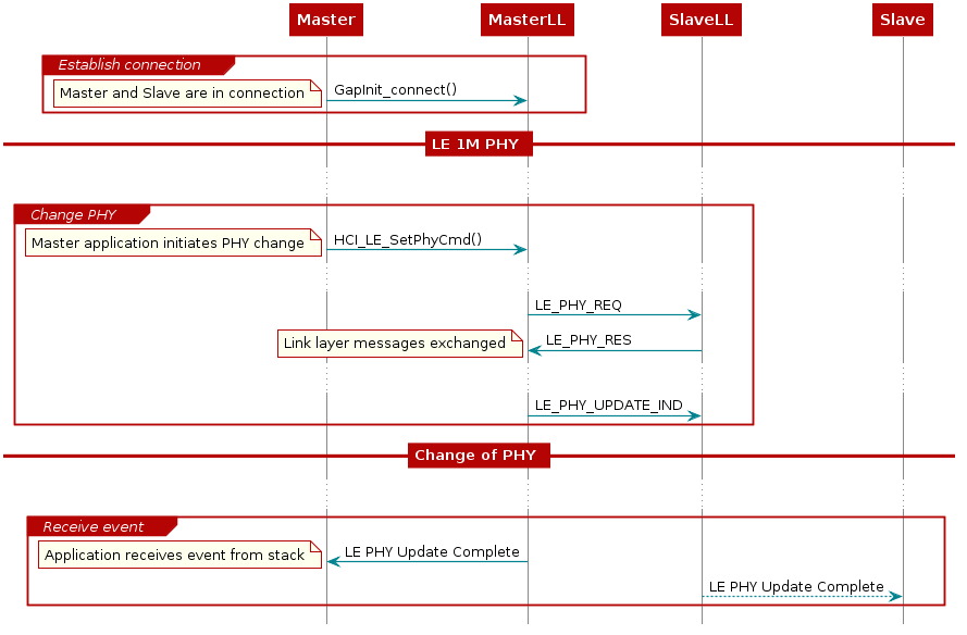
Figure 45. Sequence diagram for changing PHY by Master
Alternatively, the slave can also initiate the PHY Update Procedure as well using the same API as shown below:
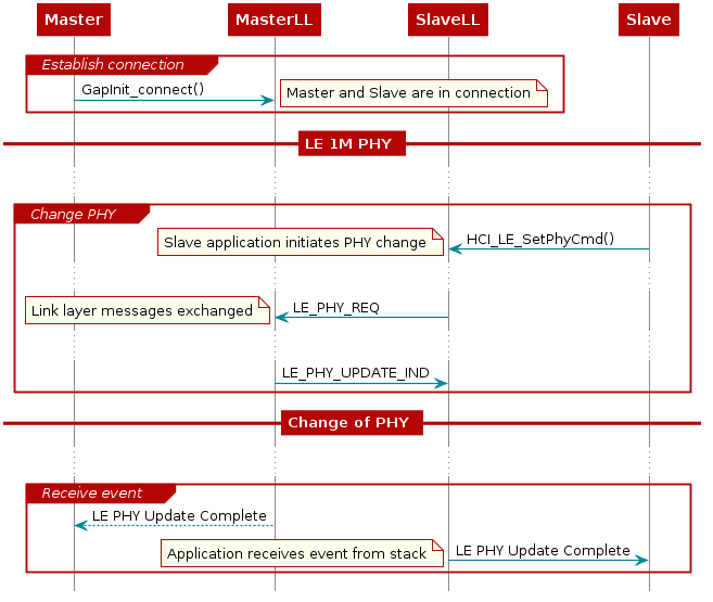
Figure 46. Sequence diagram for changing PHY by Slave
If the PHY does not change (for example, if the master tries to change to a PHY not supported by the slave), then only the side that initiated the PHY Update Procedure will get a hciEvt_BLEPhyUpdateComplete_t event. The other side will not receive a hciEvt_BLEPhyUpdateComplete_t event if the PHY is not changed. This is represented by dotted arrow lines in the flow charts above.
PHY Negotiation
Determining when the PHY will change can be determined by looking at the PHY preferences of both devices after the HCI_LE_SetPhyCmd() is called. If both devices prefers to use LE 2M PHY, the PHY will change to LE 2M PHY. If the PHY is changed to 2M due to master preference of only 2M, the slave cannot change the PHY back to 1M until the master changes its PHY preference to support 1M as well. Similarly if the PHY is changed to 1M due to the slave preference of only 1M, the master will not be able to change the PHY to 2M until the slave changes its PHY preference to support 2M as well.
If one device initiates change to a PHY not supported on other remote device, the initiating side will receive a hciEvt_BLEPhyUpdateComplete_t event with nonzero status indicating the change was not successful. If the PHY does not change after HCI_LE_SetPhyCmd() is called, the connection continues with the current PHY.
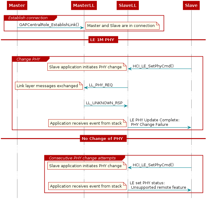
Figure 47. Sequence diagram for failed changing PHY attempts.