|
MCUSW
|
|
MCUSW
|
The figure below depicts the AUTOSAR layered architecture as 3 distinct layers, Application, Runtime Environment (RTE) and Basic Software (BSW). The BSW is further divided into 4 layers, Services, Electronic Control Unit Abstraction, MicroController Abstraction (MCAL) and Complex Drivers.

MCAL is the lowest abstraction layer of the Basic Software. It contains software modules that interact with the Microcontroller and its internal peripherals directly. Can driver is part of the Microcontroller Drivers (block, show above). Below shows the position of the Can driver in the AUTOSAR Architecture.

Can module offers following services.
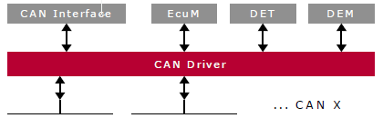
The figure below shows Can driver interaction with other modules of AUTOSAR stack.
The figure below shows the block diagram of CAN-FD module.

The Controller Area Network (CAN) is a serial communications protocol which efficiently supports distributed real-time control. CAN has high immunity to electrical interference. In a CAN network, many short messages are broadcast to the entire network, which provides for data consistency in every node of the system.
The CAN module (also known as MCAN) supports both classic CAN and CAN FD (CAN with Flexible Data-Rate) specifications. CAN FD feature allows high throughput and increased payload per data frame. The classic CAN and CAN FD devices can coexist on the same network without any conflict.
SoC can support multiple instances of the CAN module, please refer the device TRM for accurate count. Each MCAN module supports flexible bit rates greater than 1 Mbps and is compliant to ISO 11898-1:2015.
The main features of the CAN are
| Sl No | Specification | Comment / Link |
|---|---|---|
| 1 | AUTOSAR 4.3.1 | AUTOSAR Specification for CAN Driver Intranet Link |
| 2 | TDA4x TRM | Technical Reference Manual, TDA4X CAN module is detailed |
| 3 | BSW General Requirements / Coding guidelines | Intranet Link |
| 4 | Software Product Specification (SPS) | Intranet Link Requirements are derived from 1 |
The Can driver shall implement as per requirements detailed in 4, 1 and 3. It’s recommended to refer 1 for clarification.
Below listed are some of the key features that are expected to be supported
| Design ID | DES_CAN_001 |
| Requirements Covered | MCAL-2330, MCAL-2221, MCAL-2222, MCAL-2223, MCAL-2269, MCAL-2240, MCAL-2241, MCAL-2242, MCAL-2233, MCAL-2282, MCAL-2335, MCAL-2336, MCAL-2337, MCAL-2229, MCAL-2332, MCAL-4471 MCAL-2333, MCAL-2331, MCAL-2304, MCAL-200, MCAL-207, MCAL-213, MCAL-237, MCAL-244, MCAL-225, MCAL-245 |
Other general requirements that shall be implemented
| Design ID | DES_CAN_002 |
| Requirements Covered | MCAL-2284, MCAL-2285, MCAL-2250, MCAL-2246, MCAL-2247, MCAL-2251, MCAL-2265, MCAL-2225, MCAL-2287, MCAL-2234, MCAL-2254, MCAL-2294, MCAL-2295, MCAL-2296, MCAL-2248, MCAL-2252, MCAL-2388, MCAL-2303, MCAL-2360, MCAL-2361, MCAL-2362, MCAL-2302,MCAL-2405, MCAL-2400, MCAL-2401, MCAL-2403 |

| Design ID | DES_CAN_037 |
| Non Requirements | MCAL-2293, MCAL-2262, MCAL-2266, MCAL-2267, MCAL-2406, MCAL-2407, MCAL-2408, MCAL-2409, MCAL-2410, MCAL-2313, MCAL-2314, MCAL-2315, MCAL-2316, MCAL-2317, MCAL-2319, MCAL-2320, MCAL-2321, MCAL-2438, MCAL-2323, MCAL-2324, MCAL-2325, MCAL-2435, MCAL-2436, MCAL-2359, MCAL-2437, MCAL-2338, MCAL-2312, MCAL-2318, MCAL-2322, MCAL-2443, MCAL-2274, MCAL-2272, MCAL-2273, MCAL-2386, MCAL-2387, MCAL-2389, MCAL-2390,MCAL-2388 |
Below listed are assumed to valid for this design/implementation, exceptions and other deviations are listed for each explicitly. Care should be taken to ensure these assumptions are addressed.
Note that assumption 1, 2 & 3 are specified by AUTOSAR CAN specification.
Some of the critical constraints of this design are listed below
HTH’s and HRH’s shall be grouped into 2 groups, i.e. a group where a HTH/HRH is mapped to only one hardware mailbox (1:1 mapping) and another group where a HTH/HRH is mapped to a group of hardware mailboxes (1:n mapping). Number of hardware mailboxes assigned to a HTH/HRH ‘n’, can be configured through ‘CanHwObjectCount’ variable.
Please note that if we are using FIFO for receive, we cannot guarantee exact number of messages received for particular message id since it is going to common FIFO pool. For Eg: If you configure CanID1 as 0xC1, FIFO Size as 3 and CanID2 as 0xD1,FIFO Size as 2, Total Fifo Size allocated will be of 5. If you transmit 0xC1 4 time's and transmit 0xD1 2 time's, All 4 0xC1 will be stored in FIFO and only single 0xD1 will be stored in FIFO. Other 0xD1 message will be lost as there is no place to store it.
| Design ID | DES_CAN_003 |
| Requirements Covered | MCAL-2221 |
The MCAN module performs CAN protocol communication as per ISO 11898-1:2015. The bit rate can be programmed to values greater than 1 Mbps. Additional transceiver hardware is required for the connection to the physical layer (CAN bus).
For communication on a CAN network, individual message frames can be configured. The message frames and identifier masks are stored in the Message RAM. All functions concerning the handling of messages are implemented in the Message Handler. The register set of the MCAN module can be accessed directly via the module interface. These registers are used to control and configure the CAN core and the Message Handler, and to access the Message RAM.
Once the MCAN module is initialized and the INIT bit is reset to zero, the MCAN module synchronizes itself to the CAN bus and is ready for communication. After passing the acceptance filtering, received messages including Message Identifier (ID) and Data Length Code (DLC) are stored into a dedicated Rx Buffer or into Rx FIFO 0/Rx FIFO 1. For messages to be transmitted dedicated Tx Buffers and/or a Tx FIFO or a Tx Queue can be initialized or updated.
The CAN FD standard allows extended frames to be transmitted, up to 64 data bytes in a single frame and at a higher bit rate for the data phase of a frame, up to 8 Mbps. The CAN FD standard introduces the ability to switch from one bit rate to another. Extended Data Length (EDL), as shown in Figure, sets a data length of up to 8 or up to 64 data bytes. Bit Rate Switching (BRS) indicates whether two bit rates (the data phase is transmitted at a different bit rate to the arbitration phase) are enabled.

There are two variants of CAN FD frame transmission
Some of the important fields of this packet are detailed below, for other refer 2
In the CAN frames FDF = recessive (logical 1) signifies a CAN FD frame, FDF = dominant (logical 0) signifies a Classic CAN frame. In a CAN FD frame, the two bits following FDF - res and BRS, decide whether the bit rate inside of this CAN FD frame is switched. A CAN FD bit rate switch is signified by res =dominant and BRS = recessive. Note that the coding of res = recessive is reserved for future expansion of the protocol.
In case the MCAN module receives a frame with FDF = recessive and res = recessive, it will signal a Protocol Exception Event. When Protocol Exception Handling is enabled, this causes the operation state to change from Receiver to Integrating at the next sample point. In case Protocol Exception Handling is disabled the MCAN will treat a recessive res bit as an form error and will respond with an error frame.
CAN FD operation is enabled by programming the FDOE bit. In case FDOE = 1, transmission and reception of CAN FD frames is enabled. Transmission and reception of Classic CAN frames is always possible. Whether a CAN FD frame or a Classic CAN frame is transmitted can be configured via the FDF bit in the respective Tx Buffer element.
A mode change during CAN operation is only recommended under the following conditions
As detailed in section 7.3 of 1, Can would be in one of the following states. Un Initialized, Initialized, started, stopped, sleep and wakeup. Please note that "wakeup" is not supported, refer (Features Not Supported / NON Compliance)
A variable shall be maintained on per channel basis to track and maintain the state. The diagram below shows transitions of states and it’s associated service API’s.

States are
Serive API Can_SetControllerMode() can be used to transition into following states CAN_T_START, CAN_T_STOP, CAN_T_SLEEP
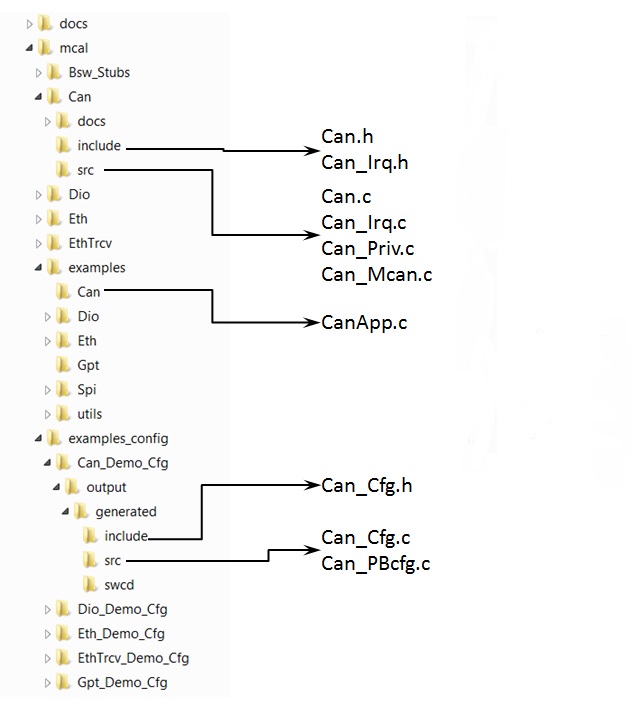
The directory structure is as depicted in figures below, the source files can be categorized under “Driver Implementation” and “Example Application”
Driver Implemented by
Example Application

Refer 5.5 of 1
| Design ID | DES_CAN_004 |
| Requirements Covered | MCAL-2227, MCAL-2231, MCAL-2230, MCAL-2232, MCAL-2228 |
Section 7 of 1, details the expected behavior and control flow for ISR implementation, please refer the same.
An separate interrupt handler shall be provided for each instance of the Can controller. e.g. If the SoC has 2 instances of Can controller, two ISR
| Design ID | DES_CAN_005 |
| Requirements Covered | MCAL-2235 |
The AUTOSAR CAN Driver Specification details mandatory parameters that shall be configurable via the configurator. Please refer section 10 of 1
| Design ID | DES_CAN_006 |
| Requirements Covered | MCAL-2168, MCAL-2141, MCAL-2186, MCAL-2170, MCAL-2171, MCAL-2172, MCAL-2147, MCAL-2151, MCAL-2150, MCAL-2165, MCAL-2155, MCAL-2156, MCAL-2158, MCAL-2159, MCAL-2160, MCAL-2162, MCAL-2142, MCAL-2190, MCAL-2184, MCAL-2182, MCAL-2187, MCAL-2188, MCAL-2140, MCAL-2163, MCAL-2195, MCAL-2154, MCAL-2144, MCAL-2146, MCAL-2166, MCAL-2145, MCAL-2157, MCAL-2173, MCAL-2167, MCAL-2153, MCAL-2152, MCAL-2143, MCAL-2164, MCAL-2196, MCAL-2191, MCAL-2198, MCAL-2200, MCAL-2201, MCAL-2216, MCAL-2202, MCAL-2203, MCAL-2204, MCAL-2205, MCAL-2206, MCAL-2207, MCAL-2209, MCAL-2210, MCAL-2211, MCAL-2215, MCAL-2199, MCAL-2213, MCAL-2208, MCAL-2161, MCAL-2185, MCAL-2192, MCAL-2193, MCAL-2194, MCAL-2169, MCAL-2174, MCAL-2181, MCAL-2176, MCAL-2177, MCAL-2178, MCAL-2179, MCAL-2180, MCAL-2175, MCAL-2149, MCAL-2148, MCAL-2197, MCAL-2183, MCAL-2189, MCAL-2212, MCAL-2214, MCAL-2439, MCAL-2440, MCAL-2334 |
Please note that ECUC requirements associated with non-supported features (Features Not Supported / NON Compliance) shall not be supported.
Following lists this design’s specific configurable parameters
| Parameter | Usage comment |
|---|---|
| CanControllerInstance | Selects Can Controller Instance configured i.e MCAN0 or MCAN1 |
| CanDefaultOSCounterId | Default Os Counter Id if node reference to OsCounter ref CanOsCounterRef is not set. The driver shall implement timed-wait for all waits (e.g. waiting for reset to complete). This timed wait shall use OS API GetCounterValue () |
| CanTypeofInterruptFunction | Type of ISR function CAT1 : interrupt void func(void) CAT2 : ISR(func) |
| CanRegisterReadbackAPI | Enable/Disable configuration readback safe TI API.If this parameter is set to true the readback API shall be supported. Otherwise the API is not supported. |
| CanDemEventParameterRefs | Reference to the DemEventParameter which shall be issued when the error timeout on blocking API call occurs. |
| CanDeviceVariant | Select SOC being used. This parameter shall be used by driver to impose device specific constraints. The user guide shall detail the device specific constraints (if any) |
| CANFDCLK | Clock frequency that is provided to the Can FD module in Mhz. This clock is required to calculate BRP(Baud Rate Prescaler) value. |
| CanLoopBackTest_Enable | Enable/Disable LoopBack test API.If this parameter is set to true the LoopBack mode shall be supported which is used for internal testing. Otherwise the API is not supported. |
The configurator shall determine the maximum number of mailboxes and controllers that are configured and generate macros to define the same. This shall be used to perform range checks on controller and mailbox configurations provided at driver initialization time. Refer section Refer section (API's)
The driver shall support both VARIANT-POST-BUILD & VARIANT-PRE-COMPILE
| Design ID | DES_CAN_036 |
In addition to dependencies listed in section 5 of 1, CAN driver shall depend on these modules to realize the required functionality, two clocks are provided to the MCAN module: the peripheral synchronous clock (interface clock - MCANx_ICLK) and the peripheral asynchronous clock (functional clock - MCANx_FCLK).
An entity such as SBL (or GEL files) will setup the required clocks for CAN modules
| Design ID | DES_CAN_037 |
| Requirements Covered | MCAL-2165 |
Errors are classified in two categories, development error and runtime / production error.
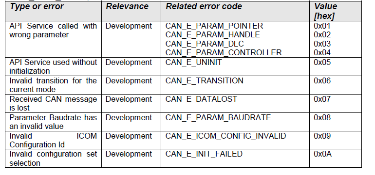
The detection of development errors is configurable (ON / OFF) at pre-compile time. The switch CanDevErrorDetection will activate or deactivate the detection of all development errors.
All detected development errors are reported to Det_ReportError service of the Development Error Tracer (DET).
| Design ID | DES_CAN_007 |
| Requirements Covered | MCAL-2327, MCAL-2329, MCAL-2326 |
The following runtime/production errors are detectable by Can driver.
| Type of Error | Related Error code | Value (Hex) |
| This error is reported if any hardware read/write event failure occurs | CAN_E_HARDWARE_ERROR | Defined By Integrator |
All detected run time errors shall be reported to Dem_ReportErrorStatus () service of the Diagnostic Event Manager (DEM).
The detailed API and interface description is available in section 8 of 1 & 4. This section describes the API supported by the MCAL driver and the requirements covered by each of the API.
The sections below lists some of key data structures that shall be implemented and used in driver implementation
These values depends on the SoC and integrators shall not modify the same.
| Type | Identifier | Comments |
|---|---|---|
| uint32 | CAN_MAX_CONTROLLER | Defines the maximum number of controllers that are configured. It’s used internally by the driver object as size parameter to allocate can controller object type structures. |
| uint32 | CAN_MAX_MAILBOXES | Defines the maximum number of mailboxes that are configured. It’s used internally by the driver object as a size parameter to allocate can controller mailbox arrays. |
| Type | Identifier | Comments |
|---|---|---|
| Can_BaudConfigType | *DefaultBaud | Pointer to the default Baud structure |
| Can_BaudConfigType | **BaudRateConfigList | List of available Baud rate structures |
| Design ID | DES_CAN_009 |
| Requirements Covered | MCAL-2444 |
| Type | Identifier | Comments |
|---|---|---|
| uint8 | ControllerId | This parameter provides the controller ID which is unique in a given CAN Driver. |
| boolean | CntrActive | Defines if a CAN controller is used in the configuration |
| uint32 | CntrAddr | Specifies the CAN controller base address.(Need to provide Message RAM Base Address, please refer MCAN Message RAM Configuration For details) |
| Can_TxRxProcessingType | RxInterrupt | CAN_TX_RX_PROCESSING_INTERRUPT/CAN_TX_RX_PROCESSING_MIXED/CAN_TX_RX_PROCESSING_POLLING |
| Can_TxRxProcessingType | TxInterrupt | CAN_TX_RX_PROCESSING_INTERRUPT/CAN_TX_RX_PROCESSING_MIXED/CAN_TX_RX_PROCESSING_POLLING |
| boolean | BusOffProcessingInterrupt | TRUE = Interrupt mode enabled FALSE = Polling mode |
| Can_ControllerInstance | CanControllerInst | Specifies theCan controller Instance selected. |
| boolean | CanFDModeEnabled | Controller is in CAN FD Mode or not. |
| Design ID | DES_CAN_010 |
| Requirements Covered | MCAL-2465 |
| Type | Identifier | Comments |
|---|---|---|
| uint8 | CanHandleType | Specifies the type (Full-CAN or Basic-CAN) of a hardware object. . |
| uint32 | MBIdType | CanIdType 0=standard 1=Extended 2= Mixed |
| Can_HwHandleType | HwHandle | Actual HW Mailbox object in the controller. |
| uint16 | CanHwObjectCount | Number of hardware objects used to implement one HOH |
| Can_MailBoxDirectionType | MBDir | Direction of Mailbox whether TRANSMIT or RECEIVE |
| const Can_ControllerType_PC | *Controller | Reference to CAN Controller to which the HOH is associated to. |
| Can_HwFilterType | **HwFilterList | List of HW Filter structure of this mailbox. |
| uint32 | HwFilterCnt | HW filter count |
| uint8 | CanFdPaddingValue | If PduInfo->SduLength does not match possible DLC values CanDrv will use the next higher valid DLC for transmission with initialization of unused bytes to the value of the corresponding CanFdPaddingValue. |
| Design ID | DES_CAN_011 |
| Requirements Covered | MCAL-2183,MCAL-2184,MCAL-2185,MCAL-2193 |
| Type | Identifier | Comments |
|---|---|---|
| uint16 | CanObjectId | Holds the handle ID of HRH or HTH. |
| Design ID | DES_CAN_012 |
| Requirements Covered | MCAL-2187 |
| Type | Identifier | Comments |
|---|---|---|
| Can_ControllerType | **CanControllerList | List of enabled Controllers. |
| uint8 | CanMaxControllerCount | MaxCount of Controller in Controller List |
| Can_MailboxType | **MailBoxList | MailBox array for all controllers. |
| boolean | MaxMbCnt | Max MailBox Count in MB list in all controller |
| uint32 | MaxBaudConfigID | Max Baud Config Index in BaudRateConfigList in all controller |
| Design ID | DES_CAN_013 |
| Requirements Covered | MCAL-2334 |
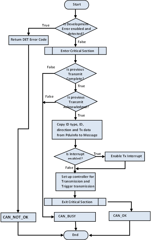
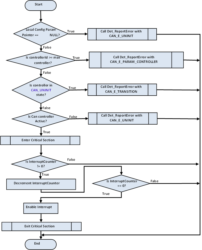
For the standard API's please refer 8.3 of 1. Sections below highlight other design considerations for the implementation.
Refer section 8.3.1.1 of 1 Below flow chart highlight key steps

| Design ID | DES_CAN_014 |
| Requirements Covered | Requirements Covered: MCAL-2286, MCAL-2281, MCAL-2283, MCAL-2342, MCAL-2341, MCAL-2218, MCAL-2217, MCAL-2220, MCAL-2245, MCAL-2244, MCAL-2280, MCAL-2249, MCAL-2279, MCAL-2343, MCAL-2236 |
Refer section 8.3.2.3 of 1

| Design ID | DES_CAN_015 |
| Requirements Covered | MCAL-2365, MCAL-2275, MCAL-2368, MCAL-2370, MCAL-2372, MCAL-2373, MCAL-2374, MCAL-2364, MCAL-2257,MCAL-2258, MCAL-2260, MCAL-2261, MCAL-2264, MCAL-2270,MCAL-2367, MCAL-2255, MCAL-2366, MCAL-2259, MCAL-2268, MCAL-2276 |
Refer section 8.3.3.1 of 1
| Design ID | DES_CAN_016 |
| Requirements Covered | MCAL-2297, MCAL-2292, MCAL-2288, MCAL-2290, MCAL-2392, MCAL-2393, MCAL-2394, MCAL-2396, MCAL-2397, MCAL-2398, MCAL-2399, MCAL-2391, MCAL-2395, MCAL-2291, MCAL-2404, MCAL-2402 |
Refer section 8.3.2.4 of 1

| Design ID | DES_CAN_017 |
| Requirements Covered | MCAL-2376, MCAL-2377, MCAL-2379, MCAL-2380, MCAL-2375, MCAL-2369, MCAL-2371 |
Refer section 8.3.2.5 of 1
| Design ID | DES_CAN_018 |
| Requirements Covered | MCAL-2382, MCAL-2377, MCAL-2378, MCAL-2383, MCAL-2384, MCAL-2385, MCAL-2381 |
Refer section 8.5.1.1 of 1

| Design ID | DES_CAN_019 |
| Requirements Covered | MCAL-2311, MCAL-2292, MCAL-2413, MCAL-2290, MCAL-2414, MCAL-2412, MCAL-2416 |
Refer section 8.5.1.3 of 1

| Design ID | DES_CAN_020 |
| Requirements Covered | MCAL-2311, MCAL-2310, MCAL-2423, MCAL-2411, MCAL-2424, MCAL-2422, MCAL-2277, MCAL-2278 |
Refer section 8.5.1.2 of 1

| Design ID | DES_CAN_021 |
| Requirements Covered | MCAL-2311, MCAL-2307, MCAL-2301, MCAL-2418, MCAL-2411, MCAL-2419, MCAL-2417, MCAL-2298, MCAL-2305, MCAL-2306, MCAL-2300, MCAL-2299, MCAL-2289, MCAL-2421 |
Refer section 8.5.1.4 of 1

| Design ID | DES_CAN_022 |
| Requirements Covered | MCAL-2311, MCAL-2310, MCAL-2411, MCAL-2427, MCAL-2428, MCAL-2426 |
Refer section 8.3.1.2 of 1

| Design ID | DES_CAN_023 |
| Requirements Covered | MCAL-2345, MCAL-2344 |
Refer section 8.5.1.5 of 1

| Design ID | DES_CAN_024 |
| Requirements Covered | MCAL-2311, MCAL-2310, MCAL-2411, MCAL-2224, MCAL-2430, MCAL-2431, MCAL-2253, MCAL-2256, |

| Design ID | DES_CAN_027 |
| Requirements Covered | MCAL-2459 |

| Design ID | DES_CAN_028 |
| Requirements Covered | MCAL-2459 |
As noted from previous implementation, the can configuration registers could potentially be corrupted by other entities (s/w or h/w). One of the recommended detection methods would be to periodically read-back the configuration and confirm configuration is consistent. The service API defined below shall be implemented to enable this detection.
| Description | Comments | |
| Service Name | Can_RegisterReadback | Can potentially be turned OFF, refer (NON Standard configurable parameters) |
| Syntax | Std_ReturnType Can_RegisterReadback(uint8 Controller, Can_RegisterReadbackType *RegRbPtr) | Can_RegisterReadbackType defines the type, that holds critical values |
| Service ID | NA | |
| Sync / Async | Sync | |
| Reentrancy | Non Reentrant | |
| Parameter in | Controller | Identifies a unique valid controller |
| Parameters out | RegRbPtr | Pointer of type Can_RegisterReadbackType, which holds read values |
| Return Value | Standard return type | E_OK or E_NOT_OK in case of invalid channel id |
The critical register listed is a recommendation and implementation shall determine appropriate registers.
This service could potentially be turned OFF in the configurator. (NON Standard configurable parameters)

| Design ID | DES_CAN_029 |
| Requirements Covered | MCAL-2452 |
| Prototype | Void Can_mcanProcessISRRx (Can_ControllerObjType *controllerObj, const Can_MailboxObjType *canMailbox, uint32 maxMbCnt) |
| Parameter | Mailbox number |
| Return Code | None |
| Functional Description | This is an internal function which is used for processing of received CAN messages |

| Design ID | DES_CAN_030 |
| Requirements Covered | MCAL-2226, MCAL-2288, MCAL-2299, MCAL-2302 |
| Prototype | Void Can_1_Int0ISR_Fun( void ) |
| Parameter | Void |
| Return Code | None |
| Functional Description | This the ISR for the CAN Interrupts. Interrupts IE0 is used for the triggering the interrupt. There are 2 interrupts for 2 controllers. All of them perform the same type of operation. |

| Design ID | DES_CAN_031 |
| Requirements Covered | MCAL-2273, MCAL-2298, MCAL-2309, MCAL-2308, MCAL-2300, MCAL-2237 |
Refer section 8.3.2.2 of 1
| Prototype | Std_ReturnType Can_SetBaudrate(Controller BaudRateConfigID) |
| Parameter In | Controller - CAN Controller ID |
| Parameter In | BaudRateConfigID - Baud rate config List Index which should be used for Baudrate configuration |
| Return Code | E_OK/E_NOTOK |
| Functional Description | This service shall set the baud rate configuration of the CAN controller. |
| Design ID | DES_CAN_032 |
| Requirements Covered | MCAL-2361, MCAL-2363, MCAL-2250, MCAL-2284, MCAL-2251, MCAL-2252 |
Refer section 8.3.2.7 of 1
| Prototype | Std_ReturnType Can_GetControllerMode(uint8 Controller, Can_ControllerStateType* ControllerModePtr) |
| Parameter In | Controller - CAN Controller ID |
| Parameter In | ControllerModePtr - Pointer to a memory location, where the current mode of the CAN controller will be stored. |
| Return Code | E_OK/E_NOTOK |
| Functional Description | This service reports about the current status of the requested CAN controller. |
| Design ID | DES_CAN_039 |
| Requirements Covered | MCAL-4372, MCAL-4373, MCAL-4374, MCAL-4375, MCAL-4376, MCAL-4379 |
Refer section 8.3.2.6 of 1
| Prototype | Std_ReturnType Can_GetControllerErrorState(uint8 Controller, Can_ErrorStateType* ErrorStatePtr) |
| Parameter In | Controller - CAN Controller ID |
| Parameter In | ErrorStatePtr - Pointer to a memory location, where the error state of the CAN controller will be stored. |
| Return Code | E_OK/E_NOTOK |
| Functional Description | This service obtains the error state of the CAN controller. |
| Design ID | DES_CAN_040 |
| Requirements Covered | MCAL-4366, MCAL-4367, MCAL-4368, MCAL-4369, MCAL-4370, MCAL-4371 |
| Prototype | Void Can_DeInit(void) |
| Parameter In | None |
| Return Code | None |
| Functional Description | This API is not standard AUTOSAR API. This service sets the internal Can Controller state to UNINIT state so that Can_Init can be invoked again and also disables Interrupts. This is required for UT test cases with different Config. |
| Design ID | DES_CAN_033 |
| Requirements Covered | MCAL-4363, MCAL-4364, MCAL-4365, MCAL-4377, MCAL-4378 |
This design expects that implementation will require to use following global variables.
| Variable | Type | Description | Default Value |
|---|---|---|---|
| Can_DriverObj | Can_DriverObjType | Can Driver object | Not defined |
| Can_DrvState | boolean | Can driver Init status flag | CAN_UNINIT |
| Design ID | DES_CAN_038 |
| Requirements Covered | SWS_BSW_00130 |
| Design ID | DES_CAN_034 |
| Requirements Covered | MCAL-2455 |
| Design ID | DES_CAN_035 |
| Requirements Covered | MCAL-2456 |
Sections below list some of the important design decisions and rational behind those decision.
The Can Receive message can be processed either through CPU or via DMA. The method chosen will impact receive throughput.
Minimal restrictions on the system and guaranteed “no receive message drop” in the system.
In case of ADAS use case, the CPU loading is low and there is no chance of CAN mailbox overflow in case Thus in all respect (complexity, efficiency), CPU mode is sufficient for the ADAS use case. So it is recommended to employ cpu mode.
Along with dedicated Tx Buffers, MCAN also supports Tx FIFO/Queue. This buffer mode is configurable and can be used in one those configurations. The mode selected will affect the priority in which will messages will go out on bus. Support of any of these modes is necessary in order to support multiplexed transmission.
Minimal restrictions on the system and support multiplexed transmission in order to avoid priority inversion.
In case of ADAS use case, the CPU loading is low and priority inversion cannot occur. Thus in all respect (complexity, efficiency), Queue mode is recommended.
The sections below identify some of the aspects of design that would require emphasis during testing of this design implementation
| Revision | Date | Author | Description | Status |
|---|---|---|---|---|
| 0.1 | 21 Aug 2018 | Sunil MS | First version | Approved |
| 0.2 | 03 Oct 2018 | Sujith S | Converted to HTML and reorganized | Approved |
| 1.0 | 01 Jun 2020 | Sunil MS | AUTOSAR 4.3.1 Updates | Approved |
 1.8.15