
5.1. Resource Allocator Module
5.1.1. Acronyms and Definitions
Abbreviation/Term |
Explanation |
|---|---|
ADC |
Analog-to-Digital Converter |
API |
Application Programming Interface |
ARXML |
AUTOSAR XML - the file format used to exchange AUTOSAR module descriptions |
ASysCtl |
Analog System Control |
AUTOSAR |
Automotive Open System Architecture |
BORL |
Brown-Out Reset Level |
BSW |
Basic Software |
CCS |
Code Composer Studio (Texas Instruments IDE) |
CMPSS |
Comparator Subsystem |
CONFIGURE mode |
The SysConfig operating mode used per-CPU that consumes the SETUP-mode |
CPUSEL |
CPU Select - hardware register field that assigns peripheral clock ownership to a specific CPU core |
EB Tresos |
Elektrobit Tresos Studio - the AUTOSAR configuration tool used by MCAL |
FRAMESEL |
Frame Select - hardware register field that selects one of four memory-mapped register frames for a peripheral |
JSON |
JavaScript Object Notation - the format of the SETUP-mode |
MCAL |
Micro-Controller Abstraction Layer |
MCU |
Micro-Controller Unit |
Q1 |
Automotive-qualified variant designator. Only Q1 variants are supported by MCAL / CDD (EB Tresos); the RA ARXML generation from SysConfig is therefore gated to Q1 devices. |
RA |
Resource Allocator |
SDK |
Software Development Kit (in this document, the F29H85x SDK, driverlib-based) |
SETUP mode |
The SysConfig operating mode used by the System Integrator to allocate device-wide resources and export SETUP artefacts consumed by CPU-level tools |
SoC |
System-on-Chip |
SysConfig |
Texas Instruments System Configuration tool. Hosts the Resource Allocator front-end |
SysCtl |
System Control |
5.1.2. Introduction to the Resource Allocator Concept
5.1.2.1. Purpose and Motivation
On F29x devices the AUTOSAR MCAL / CDD driver stack is supported only on CPU1. CPU2 and CPU3 are driven by the TI F29H85x SDK (driverlib). A typical multi-core application therefore requires two configuration tools in parallel:
EB Tresos - Elektrobit’s AUTOSAR configuration tool, used to configure the CPU1 MCAL image.
SysConfig - Texas Instruments’ System Configuration tool, used to configure the CPU2 and CPU3 SDK images.
The device-wide, SoC-level settings - resource allocation, clocktree, pin muxing, SysCtl and ASysCtl - must be consistent across all three cores for the device to boot and behave correctly. Historically these two tools have not interacted with each other. In practice this leaves projects with only two workable options, both undesirable:
Duplicate and manually keep in sync. The SoC-level settings are entered in both EB Tresos and SysConfig, and re-synced by hand whenever either side changes. This approach is time-consuming and drifts silently.
Split and hope for no conflict. Only what each tool strictly needs is configured on that side, on the assumption that the two independent sets of decisions will not overlap at the hardware level. Overlaps and conflicts are common in practice.
The problem is amplified because the MCAL configuration team and the SDK configuration team are usually different groups in the customer organisation. Neither team has full visibility into the other’s tool, and no single owner holds the whole SoC picture.
The Resource Allocator (RA) removes this coupling. SysConfig becomes the single authoring surface for every SoC-wide decision, and EB Tresos gains a direct import path so that the CPU1 MCAL configuration is derived from the same authoritative source that CPU2 and CPU3 SysConfig consume:
The SoC-wide allocation is authored once in SysConfig (SETUP mode).
Three AUTOSAR ARXML files produced by SETUP mode are imported into EB Tresos, giving CPU1 a pre-populated, consistent MCAL configuration.
CPU2 and CPU3 continue to be configured in SysConfig, but the SoC-wide settings are now locked-down. A resource assigned to CPU1 cannot inadvertently be reused on CPU2 / CPU3, and an SoC-wide decision cannot be silently overwritten from a CPU context.
A second benefit follows directly from the bridge. SysConfig offers two capabilities that are not natively available in EB Tresos:
A diagrammatic clocktree editor - PLLs, dividers and clock sources are authored visually.
Automatic pin-mux allocation and configuration - SysConfig computes valid pin/peripheral bindings.
Because the CPU1 MCAL configuration is now imported from SysConfig, both features become implicitly available to EB Tresos consumers at no additional effort.
The Resource Allocator itself is a configuration-only module - it adds no runtime code to the image. Its role is to:
Define the target device family (F29H85x, F29P32x, F29P58x).
Pin down the device variant and package.
Record which CPU owns each shared peripheral (CPUSEL) and which register frame each peripheral uses (FRAMESEL).
Capture device-wide analog and system-control settings (ASysCtl, Clocktree, SysCtl, SSU, Memory).
Make those decisions available consistently to every MCAL and CDD driver.
Because every MCAL and CDD driver reads its device-specific settings from the same Resource Allocator, two drivers cannot end up with conflicting assumptions about the same device.
Note
This document describes the CPU1 / MCAL / EB Tresos side of the Resource Allocator workflow. For the SysConfig side - SETUP-mode authoring, the resource-allocation editor, and CONFIGURE-mode consumption on CPU2 / CPU3 - refer to the Resource Allocator tool overview in the F29H85x SDK User Guide.
5.1.2.2. Key Terminology
Term |
Meaning |
|---|---|
SETUP mode |
The SysConfig operating mode entered via Define Resource Allocations on the start page (or via the |
CONFIGURE mode |
The SysConfig operating mode entered via Configure using Predefined Resource Allocations on the start page (or via |
SETUP artefacts |
The files produced by SETUP mode: three AUTOSAR module-export ARXMLs ( |
|
A reference-only consolidated JSON produced in SETUP mode that records every SoC-wide setting and every peripheral allocation. It is emitted for human inspection, diffing and auditing; it is not the input passed to CONFIGURE mode. CONFIGURE mode consumes the SETUP |
|
AUTOSAR module descriptions that mirror the allocation in a form suitable for direct import into EB Tresos. Three are emitted today: for the Resource Allocator module itself, for Port, and for Mcu. Additional modules may be added as MCAL coverage expands. |
Q1 variant gating |
RA SETUP mode itself runs on any F29x device supported by SysConfig. However, TI MCAL / CDD (the EB Tresos side) supports only Q1 (automotive-qualified) variants. As a consequence, SysConfig only emits the three |
AUTOSAR Core Type |
AUTOSAR’s model of which CPU owns which BSW partition. On F29x, the RA-assigned CPUSEL for each peripheral is what ultimately drives the AUTOSAR Core Type for that peripheral’s driver instance. |
System Integrator |
The role that authors the SoC-wide allocation in SysConfig SETUP mode. See the Roles chapter. |
CPU1 MCAL Developer |
The role that consumes the SETUP ARXMLs in EB Tresos on CPU1. See the Roles chapter. |
CPU2 / CPU3 SDK Developer |
The role that consumes the SETUP |
5.1.2.3. Architectural Overview
At a very high level, the RA flow is a producer / two-consumer pipeline. The System Integrator produces the SETUP outputs once; the CPU1 MCAL Developer consumes the three ARXMLs in EB Tresos; the CPU2 / CPU3 SDK Developer consumes the SETUP .syscfg in SysConfig CONFIGURE mode. The resourceAllocation.json is emitted alongside as a reference-only view - produced by SETUP mode but not consumed as input by either downstream tool. The three ARXMLs are emitted only when the SETUP context targets a Q1 device, because MCAL / CDD (EB Tresos) supports only Q1 variants.
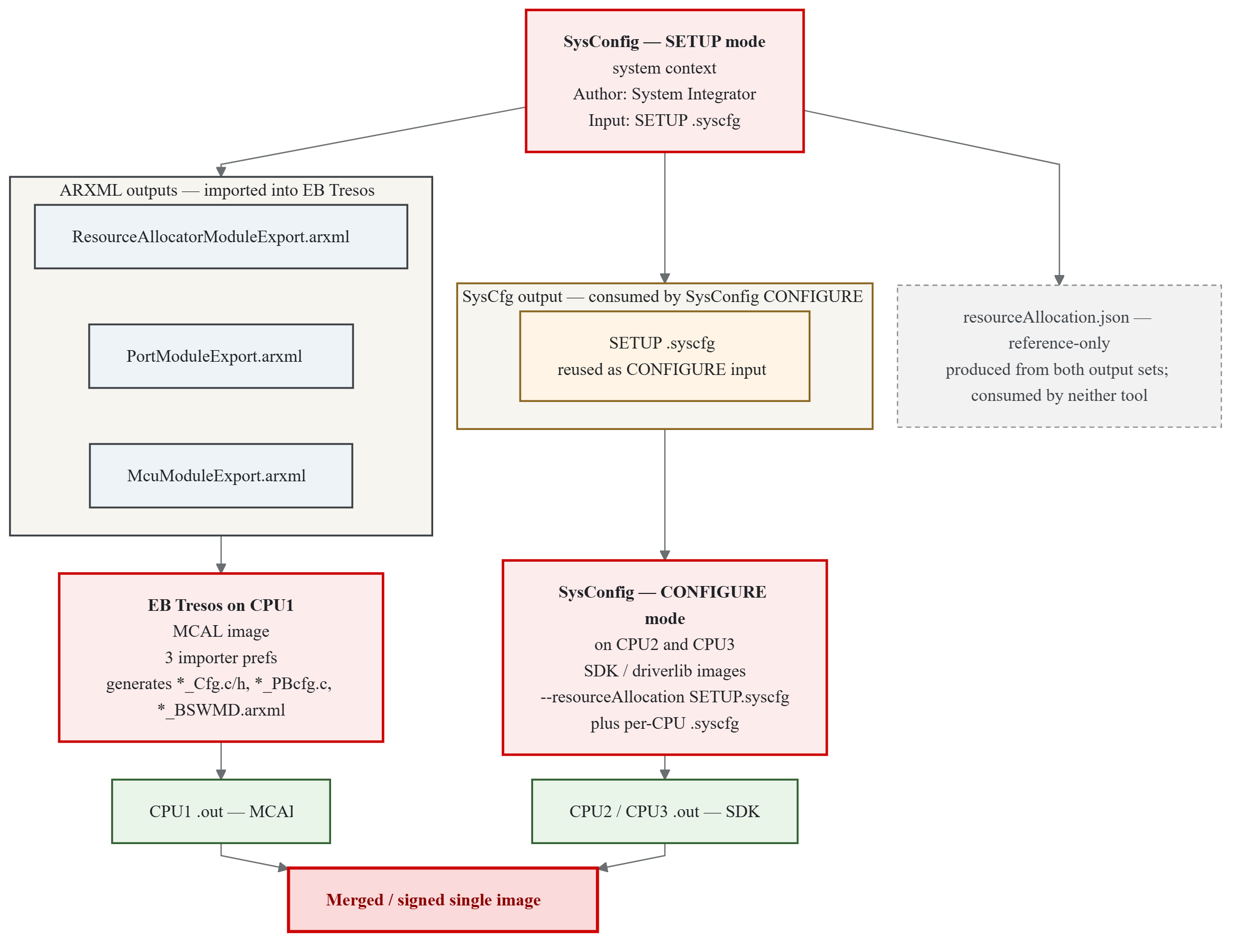
Fig. 5.1 Resource Allocator - Architectural Overview
The two consumers never need to be open at the same time. Each consumer works from files committed by the System Integrator: EB Tresos on CPU1 imports the three ARXMLs; SysConfig CONFIGURE mode on CPU2 / CPU3 re-opens the SETUP .syscfg in a locked-down view.
5.1.2.4. Hardware Features Configured by the Resource Allocator
The RA configures several critical hardware features that determine how peripherals behave on F29x devices. These are conceptual features of the platform; the RA is where they are authored, but they are enforced by the Mcu driver at initialization time on CPU1.
5.1.2.4.1. CPU1 Lockstep Mode
CPU1 Lockstep Mode is a functional-safety feature in which CPU1 and CPU2 execute the same instruction stream in redundant comparison mode:
CPU1 and CPU2 execute the same instructions simultaneously.
Hardware compares the outputs of both CPUs cycle-by-cycle.
Any mismatch triggers a safety error response.
Provides fault detection for transient and permanent CPU errors.
Configuration:
Enabled via the
CPU1_Lockstepparameter of the Resource Allocator.Requires CPU2 availability for the selected device.
Applied to hardware by
Mcu_Init()at start-up.
Use cases:
Automotive safety-critical applications (ASIL-B, ASIL-D).
Industrial functional safety systems (SIL-2, SIL-3).
Applications requiring IEC 61508 or ISO 26262 compliance.
Note
When lockstep mode is enabled, CPU2 cannot be used independently. Both cores operate as a single logical processing unit.
5.1.2.4.2. CPU Selection (CPUSEL)
CPU Selection determines which CPU core owns and controls a peripheral instance:
Is automatically assigned based on the Context configuration.
Peripherals inherit CPU selection from their parent Context’s
Coreparameter.Controls peripheral clock gating - only the owning CPU can enable/disable the peripheral clock.
Behavior:
The owning CPU has exclusive control over the peripheral’s clock enable.
Other CPUs can access the peripheral’s registers (if a frame is granted to them via FRAMESEL) but cannot control its clock.
Ensures deterministic peripheral initialization and power management.
Note
CPUSEL is automatically configured by the Resource Allocator based on the Context assignment. Users do not directly write CPUSEL values. Only CPU1 can write the CPUSEL registers; therefore the CPUSEL programming for the entire device is performed once during CPU1’s Mcu_Init().
5.1.2.4.3. Frame Selection (FRAMESEL)
Frame Selection enables optimized multi-core peripheral access by providing multiple memory-mapped address spaces for each peripheral:
Provides four independent frames (
FRAME0,FRAME1,FRAME2,FRAME3) per peripheral.Each frame has its own base address for memory-mapped access.
Enables simultaneous access from different CPU cores without arbitration stalls.
Reduces bus contention in multi-core applications.
Configuration:
User-configurable via the
Frameparameter for each peripheral instance in the Resource Allocator.Available for all peripheral types (CAN, SPI, LIN, UART, etc.).
Use cases:
Multi-core applications where different CPUs need concurrent peripheral access.
Reducing bus arbitration delays in time-critical applications.
Optimizing peripheral bandwidth utilization across multiple initiators.
Note
All frames access the same physical peripheral hardware. Frame selection only affects the memory-mapped address used for register access, not the peripheral functionality.
5.1.3. Roles Involved in the Resource Allocator Workflow
The Resource Allocator workflow separates the SoC-wide configuration authority from the per-CPU configuration authority. Three distinct project roles are involved. Depending on team size, one person may hold more than one role, but the tools, responsibilities and deliverables remain distinct in each case.
System Integrator. Authors the SoC-wide allocation in SysConfig (SETUP mode). Typically a one-time step at project start, revisited only when the SoC-wide layout changes.
CPU1 MCAL Developer. Configures the AUTOSAR MCAL / CDD stack in EB Tresos. Imports the ARXMLs produced by the System Integrator and refines the CPU1 configuration.
CPU2 / CPU3 SDK Developer. Configures the SDK (driverlib) stack for CPU2 or CPU3 in SysConfig (CONFIGURE mode), consuming the SETUP allocation.
5.1.3.1. Roles at a Glance
Aspect |
System Integrator |
CPU1 MCAL Developer |
CPU2 / CPU3 SDK Developer |
|---|---|---|---|
Tool |
SysConfig - SETUP mode (Define Resource Allocations) |
EB Tresos (importing SETUP ARXMLs) |
SysConfig - CONFIGURE mode (Configure using Predefined Resource Allocations) |
Software stack |
- |
AUTOSAR MCAL / CDD |
TI F29H85x SDK (driverlib) |
Frequency |
Once per project (revisited when the SoC-wide layout changes) |
Ongoing throughout development |
Ongoing throughout development |
Scope |
Whole device - every core, every shared peripheral, every pin |
CPU1 only |
The relevant CPU only (CPU2 or CPU3) |
Owns |
The SETUP |
The EB Tresos project ( |
The per-CPU |
Cannot change |
Another CPU’s driver-level details |
Anything locked by the System Integrator in SETUP |
Anything locked in SETUP; resources not allocated to the CPU |
Deliverable |
System-wide allocation files, consumed once by MCAL and once by SDK |
The CPU1 MCAL |
The CPU2 or CPU3 SDK |
The System Integrator decides what - which peripheral goes where, which core owns which pin, and what the clocktree looks like. The MCAL Developer and the SDK Developer decide how - how each CPU’s peripherals are actually driven and how the CPU-local application logic behaves. In many customer organizations these roles sit in separate teams; the Resource Allocator lets those teams work independently without stepping on each other’s decisions.
5.1.3.2. Hand-off Between Roles
The three roles interact only through files that the System Integrator commits to the project. No two roles need to work simultaneously or share a live environment.
From the System Integrator to the CPU1 MCAL Developer. The System Integrator commits three ARXML files (
ResourceAllocatorModuleExport.arxml,PortModuleExport.arxml,McuModuleExport.arxml) alongside the reference-onlyresourceAllocation.json. The CPU1 MCAL Developer imports the three ARXMLs into EB Tresos via three matched importer preferences (SysCfg_ResourceAllocator_Importer,SysCfg_Port_Importer,SysCfg_Mcu_Importer) that point at those files. EB Tresos then generates the CPU1 MCAL configuration inoutput/{include,src,swcd}/as usual. See Chapter 4 for details.From the System Integrator to the CPU2 / CPU3 SDK Developer. The System Integrator also commits the SETUP
.syscfgitself. The CPU2 / CPU3 SDK Developer opens the per-CPU.syscfgin SysConfig with the SETUP.syscfgsupplied via--resourceAllocation(or, in the GUI, by selecting Configure using Predefined Resource Allocations and pointing at the SETUP file). SysConfig loads the allocation and enforces every SoC-wide decision as read-only in the CPU context. Only the resources allocated to that CPU can be added; SETUP-locked fields are greyed out. TheresourceAllocation.jsonis not consumed here - it exists purely as a reference view.
Once these hand-offs are complete, each CPU builds independently. The CPU1 MCAL binary and the CPU2 / CPU3 SDK binaries are produced by their respective owners and merged into the final image at build time.
5.1.3.3. What Each Role Does
System Integrator responsibilities:
Select the device, variant and package. To produce ARXMLs for EB Tresos, a Q1 variant must be selected (MCAL / CDD supports only Q1 devices; SysConfig emits the
*ModuleExport.arxmlfiles only in that case). SETUP mode itself is not restricted to Q1.Configure every SoC-wide setting: Clocktree, SysCtl, ASysCtl (temperature sensor, analog reference, VREG, BORL, internal test node, CMPSS mux), SSU, Memory Regions, LINK and STACK.
Allocate every shared peripheral instance to a specific CPU using the Assigned CPU field. This includes MCAL-driven peripherals (Can, Spi, Lin, Uart, Adc, Pwm, Ecap, Sent, I2c, Xbar, Cmpss) and non-MCAL peripherals owned by the SDK on CPU2 / CPU3 (Eqep, Sdfm, Pmbus, Dac, Clb, FsiTx, FsiRx, Dcc, Epg, Wadi, DLTFifoRegs, Error_Aggregator, ESM - see Non-MCAL Peripheral Allocation).
Give each allocation a descriptive, functionally meaningful name - for example,
mySPI_MotorControlrather thanmySPI1. CONFIGURE-mode consumers select allocations by these names; meaningful naming greatly improves the downstream experience.Configure pin muxing for the entire device and per-peripheral frame selection.
Commit the SETUP
.syscfg(consumed by SysConfig CONFIGURE mode) and the three*ModuleExport.arxmlfiles (imported by EB Tresos). TheresourceAllocation.jsonis typically committed alongside for auditability.
CPU1 MCAL Developer responsibilities (the primary audience of this User Guide):
Import the three SETUP ARXMLs into EB Tresos and refresh the project, following the strategy per module described in Step-by-Step Guide: Export from SysConfig and Import into EB Tresos.
Once imported, the SoC-wide settings appear in EB Tresos. The remaining focus is on AUTOSAR-specific parameters that SysConfig does not author - notifications, DEM / DET mapping, module-level tuning, interrupt handlers, application data flow - plus per-driver refinement.
Verify that every needed parameter has been imported. Fill in what the SysConfig side does not know about (see What the Importer Does and Does Not Cover and Parameters Requiring Manual Configuration in EB Tresos).
Build and integrate the CPU1 MCAL application.
CPU2 / CPU3 SDK Developer responsibilities:
Open the per-CPU
.syscfgin SysConfig with the SETUP.syscfgsupplied via--resourceAllocation.Add instances of the modules allocated to the CPU, and use the Allocation field to bind each instance to the slot authored by the System Integrator.
Configure the CPU-local details that remain editable. Everything locked in SETUP is read-only.
Build the CPU2 or CPU3 SDK application. The result is merged with the CPU1 MCAL image at build time.
Note
For the SysConfig side of the workflow - SETUP-mode authoring in detail and CONFIGURE-mode UX on CPU2 / CPU3 - refer to the Resource Allocator tool overview in the F29H85x SDK User Guide. This User Guide focuses on the CPU1 / MCAL / EB Tresos side of the same workflow.
5.1.3.4. Practical Considerations
Independence between roles. Once the SETUP artefacts are committed, CPU images build with no live dependency on SysConfig or EB Tresos being open on any other host. Every host has everything needed locally.
Tool-version matching. Both the SETUP
.syscfgheader and the referenceresourceAllocation.jsonrecord the SysConfig version used to author them. CONFIGURE mode should use the same SysConfig version for reproducible results.Override for RA-locked EB Tresos parameters. RA-locked parameters are non-editable in EB Tresos by default. EB Tresos provides an option to re-enable editing for projects that choose not to use the SysConfig-based flow.
5.1.3.5. Visual Overview
The complete producer / two-consumer pipeline - including the ARXML hand-off to EB Tresos on CPU1 and the SETUP .syscfg hand-off to SysConfig CONFIGURE on CPU2 / CPU3 - is illustrated by the Architectural Overview diagram. A concrete instance of the same flow is walked through end-to-end in Reference Example: RA_Example_SysCfgToEbIntegration.
5.1.4. Configuration in SysConfig (SETUP and CONFIGURE Modes)
This chapter walks through opening SysConfig with the SETUP flag enabled, authoring the resource allocation for the whole SoC, and producing the SETUP-mode outputs — the SETUP .syscfg itself (consumed by SysConfig CONFIGURE mode on CPU2 / CPU3), the three *ModuleExport.arxml files (imported into EB Tresos on CPU1, and emitted only when the SETUP context targets a Q1 device because MCAL / CDD supports only Q1 variants), and the reference-only resourceAllocation.json.
For background reading on the SysConfig-side UI, see the F29H85x SDK User Guide:
5.1.4.1. SysConfig Step-by-Step Walk-through
Open SysConfig, select the board, device package and variant as needed, and under Mode, select Define Resource Allocations.
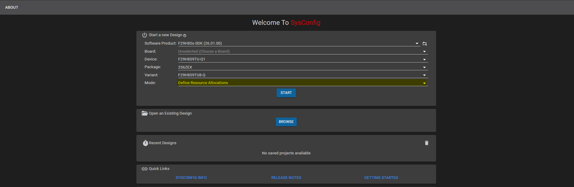
Fig. 5.2 Selecting Define Resource Allocations in SysConfig
Under Software Platforms, add a CPU1 container and select Platform Type as AUTOSAR. The right-hand side section of the SysConfig window shows a live preview of the generated ARXML files, which updates as the allocation is configured in the following steps.
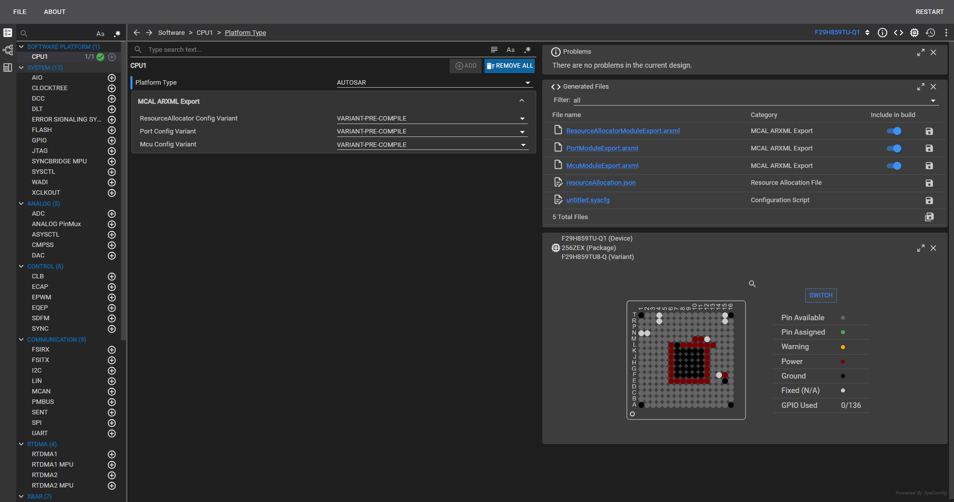
Fig. 5.3 Adding a CPU1 container and selecting Platform Type AUTOSAR
For clock settings, you can either configure them in the CLOCKTREE container on the main page, or select the Clock Tree window to get a more visual representation of the clock architecture and flow.
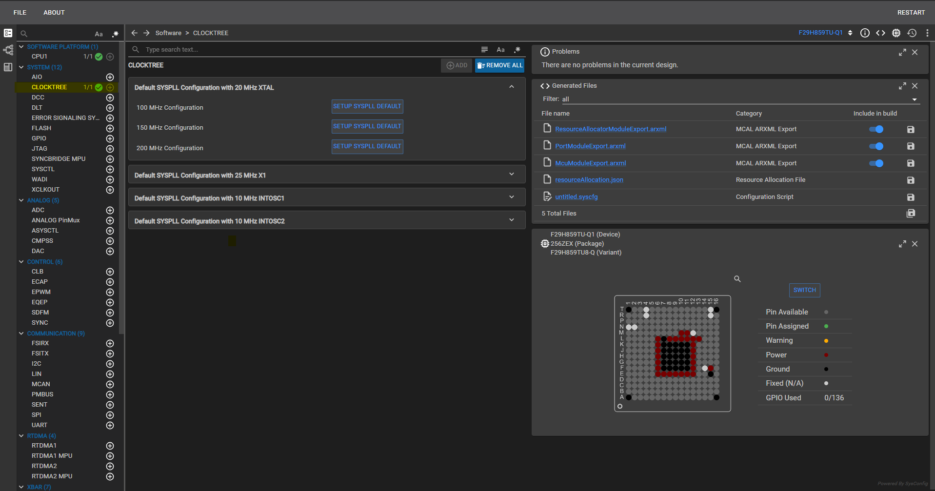
Fig. 5.4 Configuring clock settings in the CLOCKTREE container
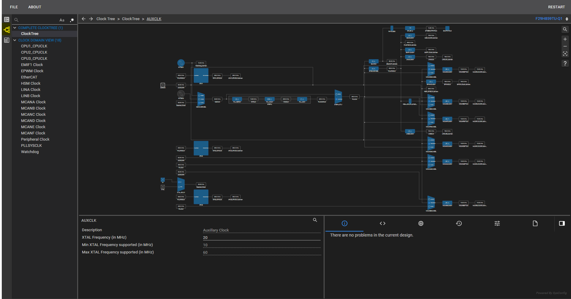
Fig. 5.5 Configuring clock settings in the Clock Tree window
Allocate the modules you want to use and configure the CPU associated with each module. Fill in the parameters under System Configuration, PinMux Qualification, PinMux Peripheral and Pin Configuration as required.
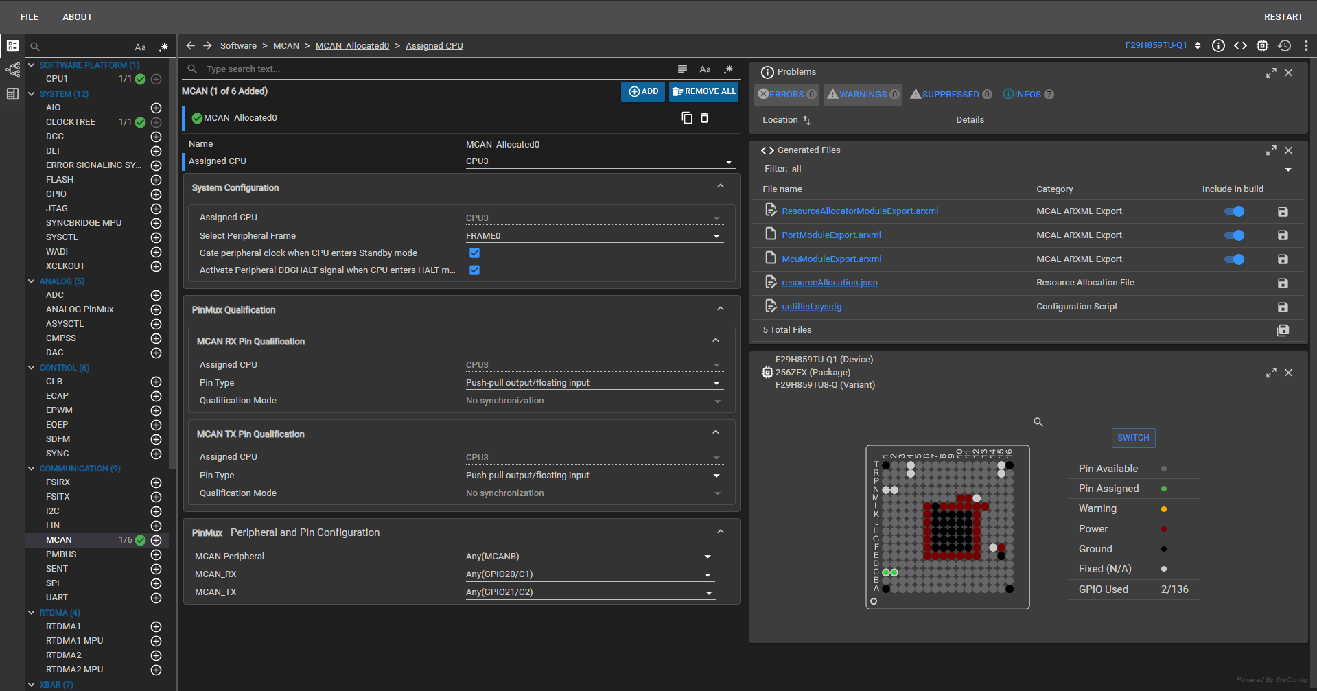
Fig. 5.6 Allocating modules, assigning CPU ownership, and configuring pin mux settings
Save the
.syscfgfile, then open the same file with Mode set to Configure using Predefined Resource Allocations to configure the allocated modules.
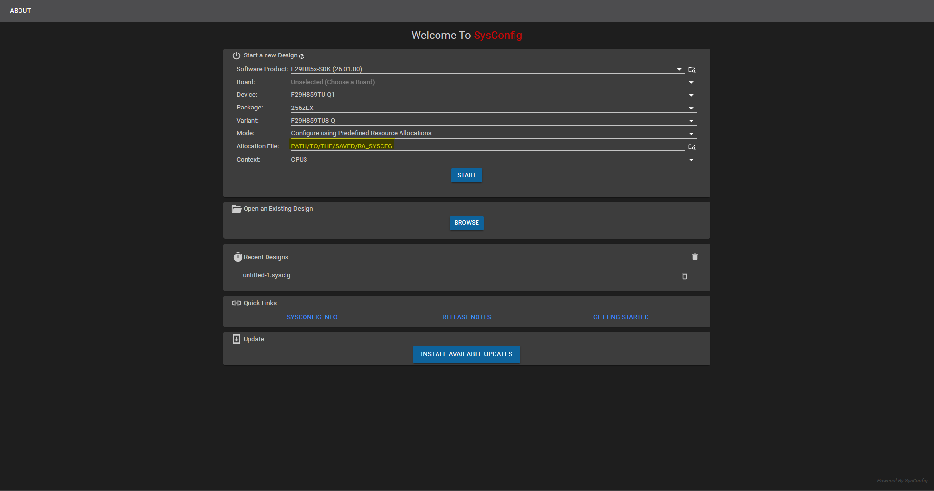
Fig. 5.7 Opening the SETUP .syscfg with Mode set to Configure using Predefined Resource Allocations
In the opened
.syscfgfile, you can find the modules allocated to the picked CPU and further configure them.
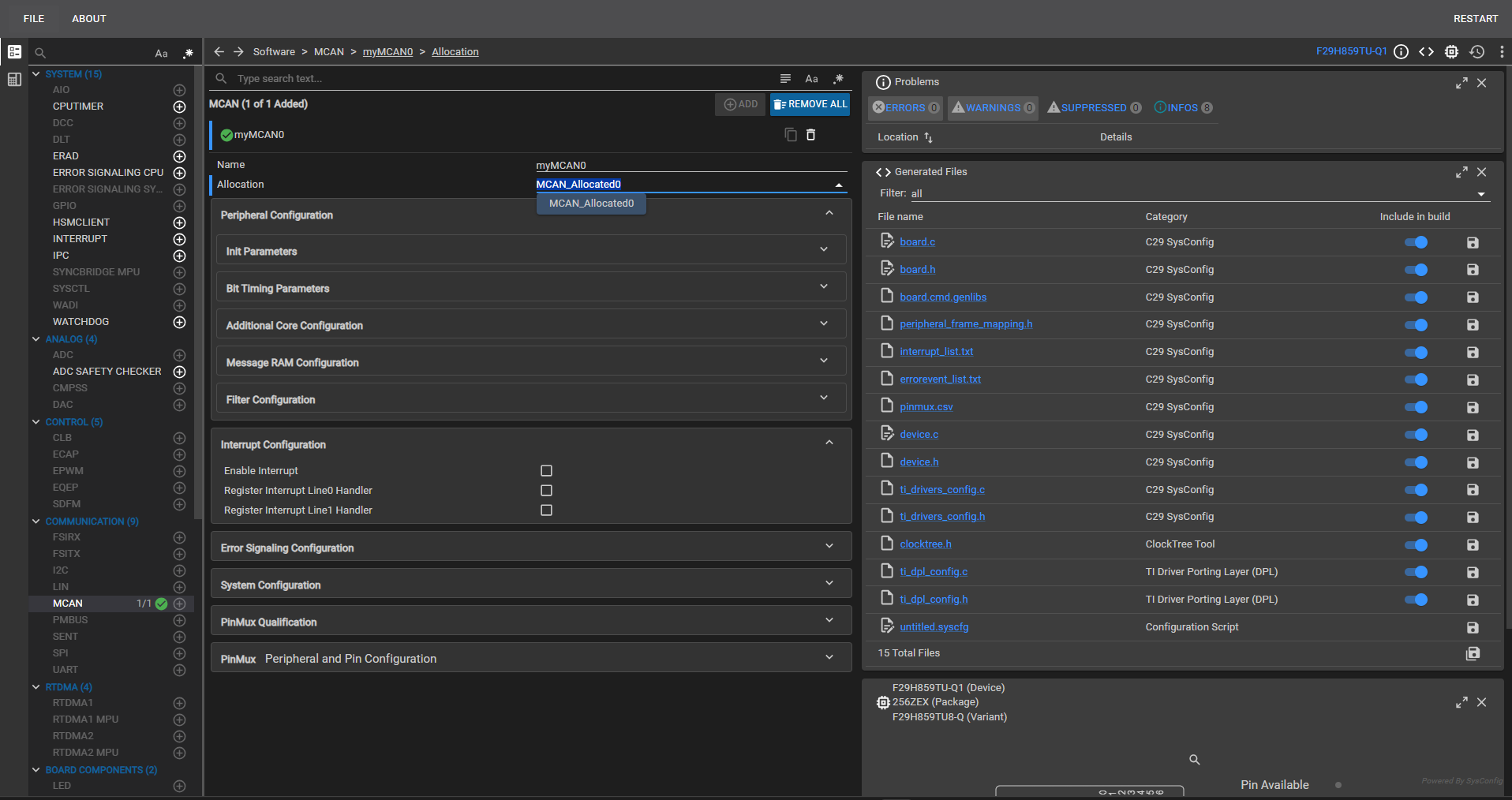
Fig. 5.8 Viewing and configuring the modules allocated to the selected CPU
Once SETUP mode has been completed and its outputs are on disk, continue with the Step-by-Step Guide: Export from SysConfig and Import into EB Tresos chapter to import the ARXMLs into the EB Tresos project for CPU1.
Note
The three *ModuleExport.arxml files are only emitted by SETUP mode when the SETUP context targets a Q1 device, because MCAL / CDD (EB Tresos) supports only Q1 variants. See ARXML Files Are Not Produced on a Non-Q1 Device for the corresponding troubleshooting entry.
5.1.5. Step-by-Step Guide: Export from SysConfig and Import into EB Tresos
Once SETUP mode has produced the three *ModuleExport.arxml files (and the reference resourceAllocation.json alongside), the ARXMLs must be surfaced to EB Tresos so that the MCAL side of the project can consume them. This chapter walks through the CPU1 side of the hand-off: locating the SETUP outputs, wiring the three EB Tresos importers (SysCfg_ResourceAllocator_Importer, SysCfg_Port_Importer, SysCfg_Mcu_Importer) to those files, choosing the right import Strategy for each module, running the import, and refreshing the EB Tresos project so that the RA-locked parameters appear correctly and the usual *_Cfg.{c,h} / *_PBcfg.c / *_BSWMD.arxml are generated under output/{include,src,swcd}/.
5.1.5.1. Recommended Import Strategy per Module
Every EB Tresos importer supports a Strategy field (visible as Strategy=Replace / Strategy=Merge in the underlying pref_imp_exp_SysCfg_*_Importer.xdm files). The correct choice depends both on which module is being imported and on whether the EB Tresos project has been manually edited since the last import.
Recommended defaults when the project is first started (i.e. the EB Tresos project has just been created and no user edits have been made yet):
Module |
Preparation before first import |
Import Strategy |
|---|---|---|
|
None (module is added by the import itself) |
Replace |
|
None (module is added by the import itself) |
Replace |
|
Load the Recommended Configuration first (see Recommended Configuration (EB Tresos)) so that AUTOSAR-specific parameters that SysConfig does not know about are pre-populated. |
Merge |
The reason Mcu is treated differently is that the SysConfig-generated McuModuleExport.arxml only contains what SysConfig itself authored (clocks, PLL, CPUSEL / FRAMESEL, ASysCtl runtime settings applied by Mcu_Init()). The recommended Mcu configuration additionally supplies AUTOSAR-specific containers and parameters (mode configurations, notifications, error handling, etc.) that SysConfig has no awareness of. Loading the Recommended Configuration first and then importing the SysConfig ARXML with Strategy=Merge combines both sources - SysConfig’s device-specific values on top of a fully-populated AUTOSAR configuration.
5.1.5.2. What the Importer Does and Does Not Cover
The ARXML import in EB Tresos does not necessarily configure every configurable parameter present in the three imported modules - especially AUTOSAR-specific parameters that SysConfig has no visibility into. Concretely:
Any parameter that exists in the module’s AUTOSAR container schema but is not authored by SysConfig will remain at its EB Tresos default after import (or blank, if the container itself was created only for the SysConfig-authored subset).
SysConfig cannot supply AUTOSAR notification callbacks, DEM/DET error mapping, service-layer references, or any parameter that lives above the pure device-configuration layer.
Users are therefore recommended to:
Verify which configurations were imported - open each of the three imported modules (
ResourceAllocator,Port,Mcu) and inspect every container that the project needs.Manually configure any parameters that were not imported, using EB Tresos’s normal editors. These are the parameters that SysConfig does not (and cannot) author.
Re-run
Auto-Calcin EB Tresos after the manual step so any derived values are recomputed against the merged configuration.
5.1.5.3. Parameter Value Origin Icons
EB Tresos overlays a small icon on a parameter’s type icon to indicate the origin of its current value - default, calculated, preconfigured, recommended, or imported. Use these overlays to quickly distinguish parameters that were imported from SysConfig from those still at their EB Tresos default.
To verify the imported values, check for an I mark on the parameter’s type icon.

Fig. 5.9 The I overlay icon indicating an imported parameter value
Note
For more details on parameter icons and their behavior, refer to Section 5.4.1.1 Sections and parameters in {EB_INSTALLATION_PATH}/tresos/doc/2.0_EB_tresos_Studio/2.1_Studio_documentation_users_guide.pdf
5.1.5.4. Parameters Requiring Manual Configuration in EB Tresos
SysConfig does not author every parameter present in the ResourceAllocator, Mcu and Port module schemas. The items listed below have no corresponding collateral in SysConfig - after import, they are either left at their EB Tresos default or left unpopulated - and must be reviewed and configured manually.
ResourceAllocator
Container |
Manual configuration required |
|---|---|
CMPSS |
|
PWM |
High-Resolution (HR) calibration values are not available in SysConfig. |
Epg |
Not available in SysConfig. |
ASysCtl |
The voltage regulator and Brown-Out Reset switch settings are not present in SysConfig; the external voltage defaults to 3.3 V. |
ADC |
Only the |
Wadi |
Not available in SysConfig. |
ESM |
Not available in SysConfig. |
Error_Aggregator |
Not available in SysConfig. |
Mcu
Container |
Manual configuration required |
|---|---|
CPU Timer |
Not available in SysConfig. |
Port
Container |
Manual configuration required |
|---|---|
ADC external mux |
Not available in SysConfig. |
5.1.5.5. Re-Import Strategy After Manual Edits
Once the EB Tresos project has been manually modified (either to fill in AUTOSAR-specific parameters that SysConfig did not author, or to tune module-level behavior), subsequent imports of updated *ModuleExport.arxml files should use Strategy=Merge for all three modules - not just for Mcu.
The rationale is symmetric to the initial-import guidance:
Strategy=Replaceon a subsequent import will overwrite the user’s manual edits with the SysConfig-authored subset only, silently losing every AUTOSAR-specific parameter the user filled in.Strategy=Mergepreserves the manually configured settings and layers the fresh SysConfig-authored values on top, updating only the SysConfig-owned parameters.
The rule of thumb:
Replaceis only safe on a virgin project. Once any parameter has been touched by hand in EB Tresos, always re-import withMerge.
Note
The current committed EB Tresos preferences in the reference example RA_Example_SysCfgToEbIntegration (see Reference Example: RA_Example_SysCfgToEbIntegration) match this per-module recommendation - Strategy=Replace for ResourceAllocator and Port, Strategy=Merge for Mcu. See CPU1 - EB Tresos Path (MCAL) for details. Projects derived from the example that begin hand-editing the EB Tresos configuration for ResourceAllocator or Port should switch those two importers to Strategy=Merge as well before re-importing.
5.1.5.6. EB Tresos Step-by-Step Walk-through
For installing EB Tresos and activating the license, follow the “Getting started with EB Tresos” guide: MCAL_Configuration_and_EB_Tresos.md.
Create an EB Tresos configuration project. The
Mcu,ResourceAllocator, andPortmodules are mandatory and must be added to the project.Create Importers for the three
*ModuleExport.arxmlfiles generated by SysConfig - one each forResourceAllocator,McuandPort.
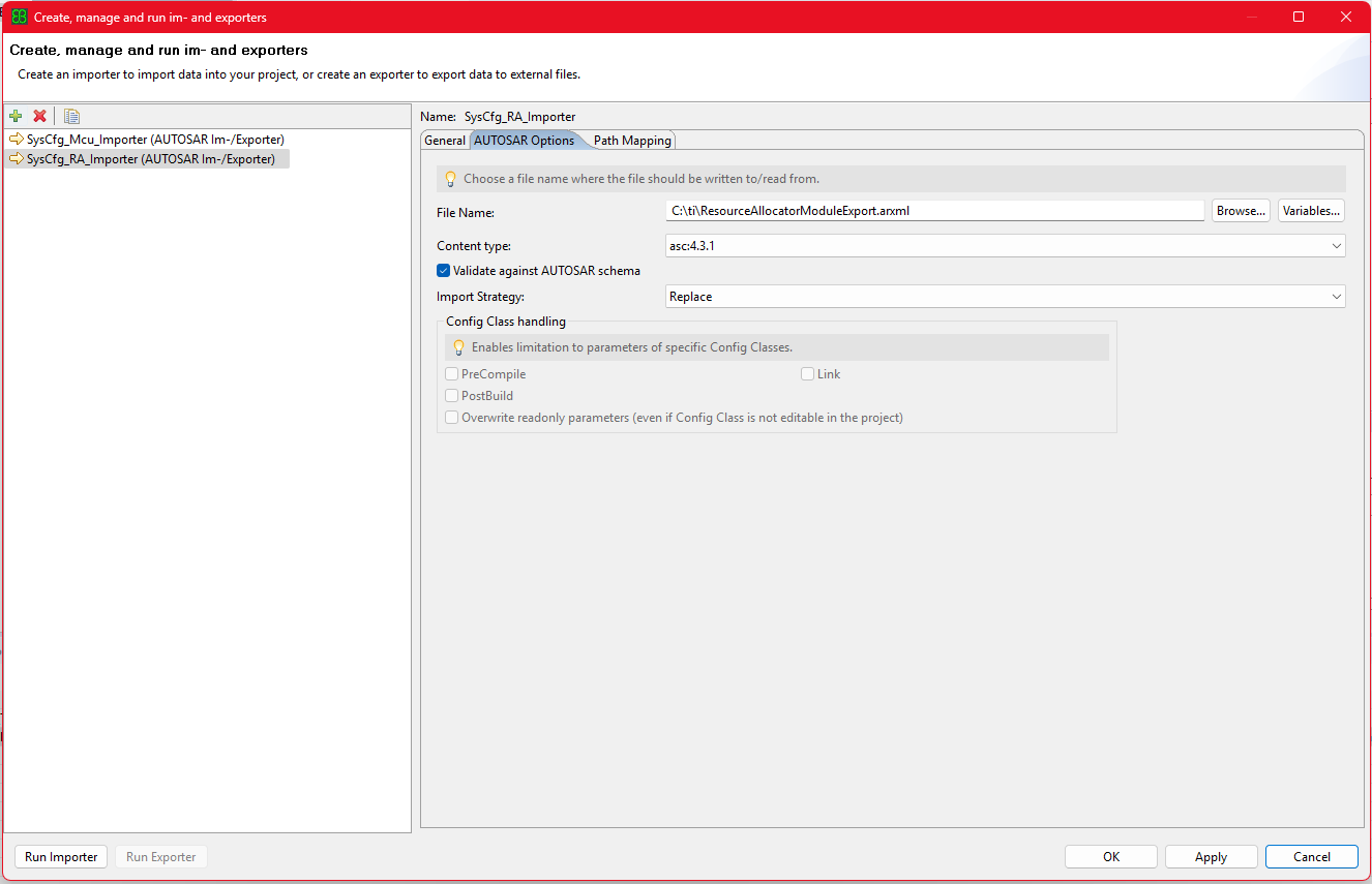
Fig. 5.10 Adding the ResourceAllocator ARXML as an importer
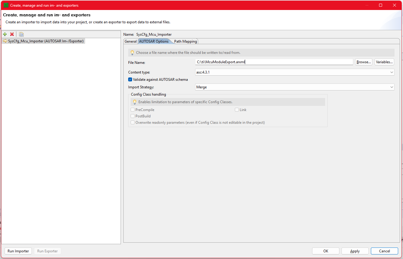
Fig. 5.11 Adding the Mcu ARXML as an importer
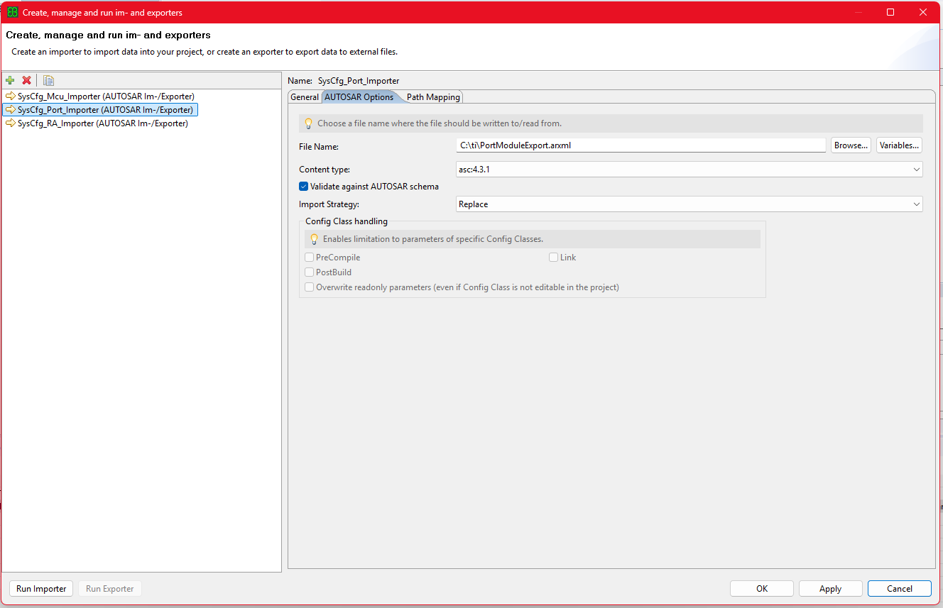
Fig. 5.12 Adding the Port ARXML as an importer
We recommend to also create a MultiTask Wizard in EB Tresos for ease of use, with the tasks in the order given in the image below.
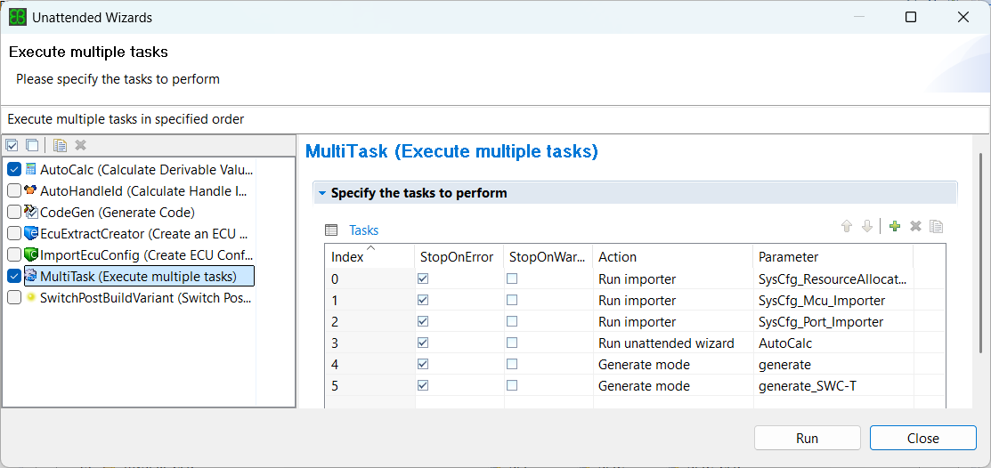
Fig. 5.13 Adding a MultiTask with tasks in the required order
Once the MultiTask command is run, the importer imports the values present in ARXMLs coming from SysConfig and updates the corresponding parameters in your project XDMs. Go through each modules and check for the updated parameters.
Open the
ResourceAllocatormodule and check the device info reflected on the General page.
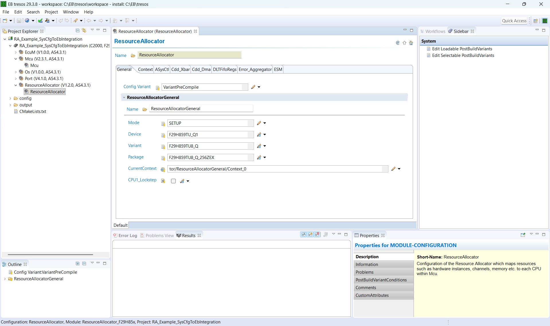
Fig. 5.14 Checking the device info reflected on the ResourceAllocator General page
Then check the CPU being configured according to the SysConfig configuration.
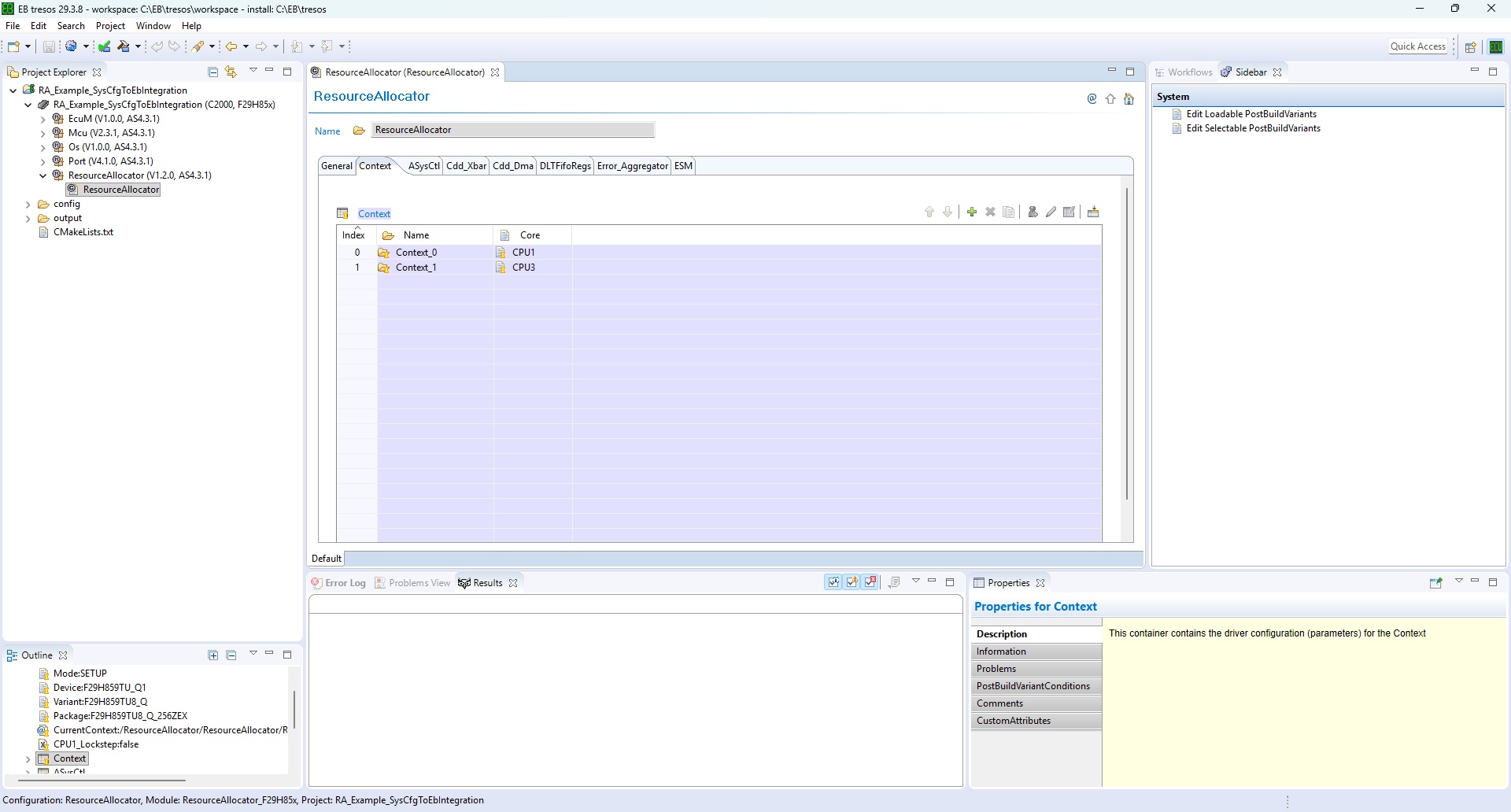
Fig. 5.15 Checking the CPU configured in the ResourceAllocator module
Then, within the CPU container, check the modules being allocated to that CPU.
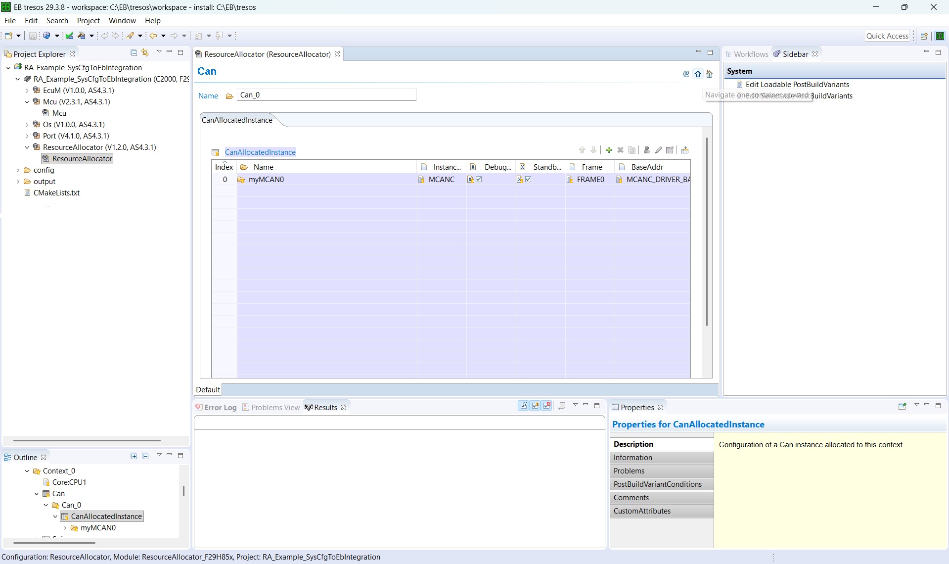
Fig. 5.16 Checking the modules allocated to the CPU within the CPU container
Within
Mcu, theMcuClockSettingConfigcontainer is updated based on the configurations made in the SysConfig Clock Tree. TheMcuClockSettingIdparameter is not populated by the import and must be configured manually to match the ID passed to theMcu_InitClockAPI call.
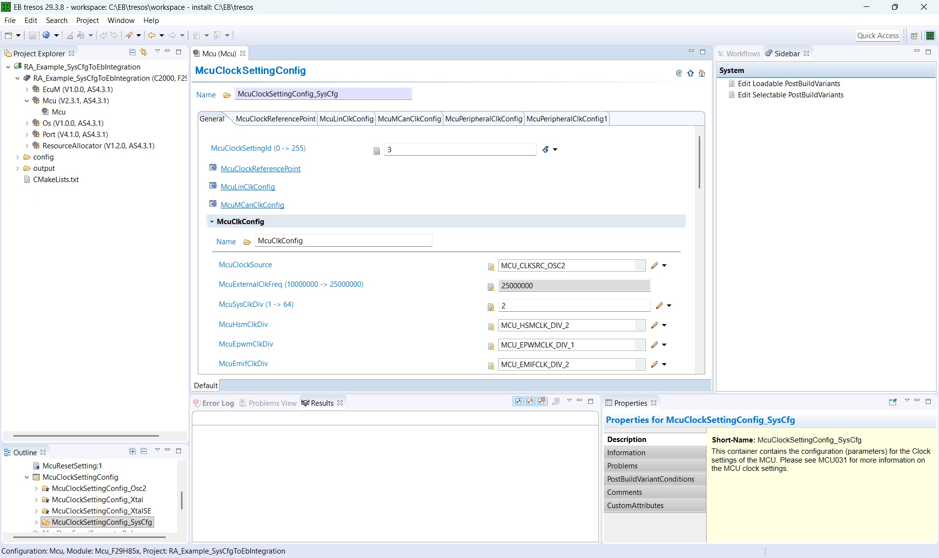
Fig. 5.17 McuClockSettingConfig container updated from SysConfig Clock Tree settings
Then check if the pin mux of the selected modules is reflected in the
Portmodule as well.
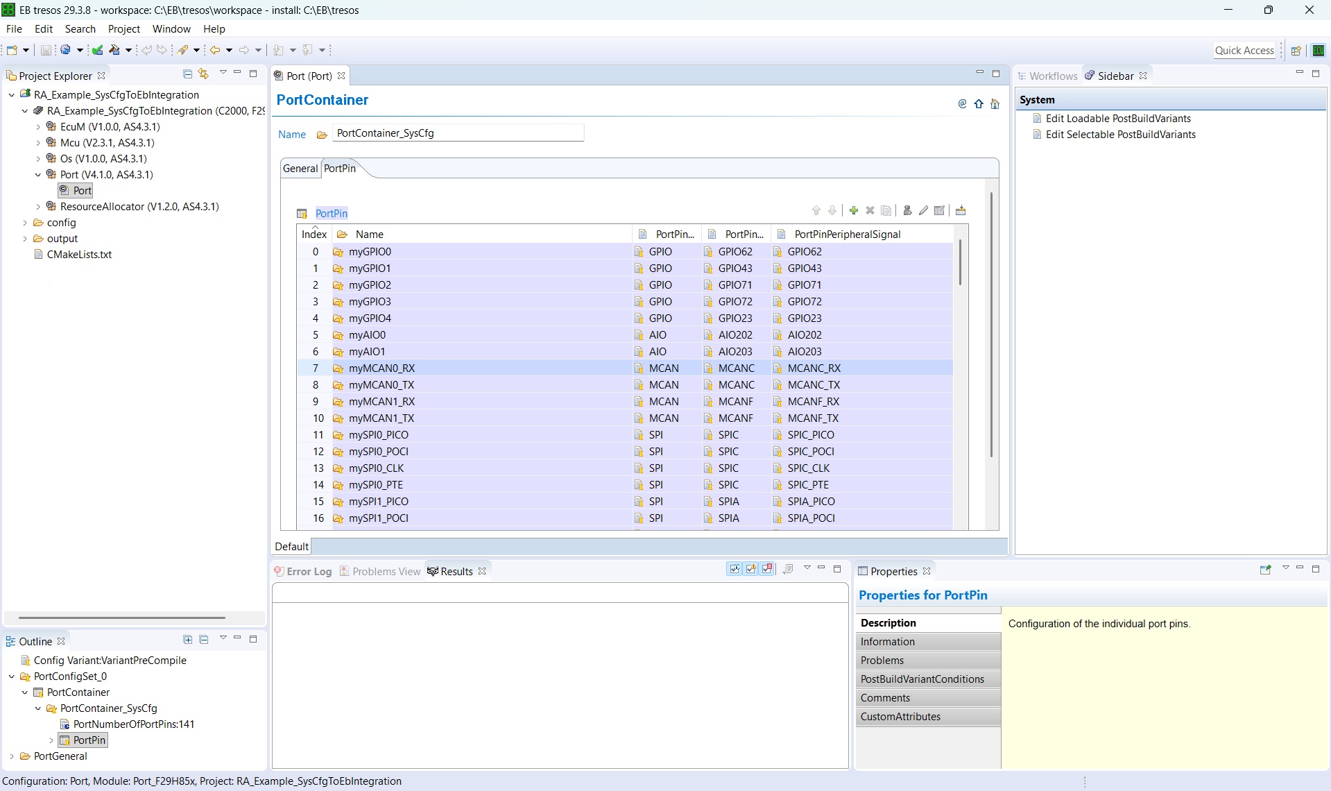
Fig. 5.18 Verifying the pin mux of the selected modules in the Port module
Then, within the container, check each parameter’s origin icon (see Parameter Value Origin Icons) to distinguish values that were auto-calculated or imported from SysConfig from those that still require manual configuration.
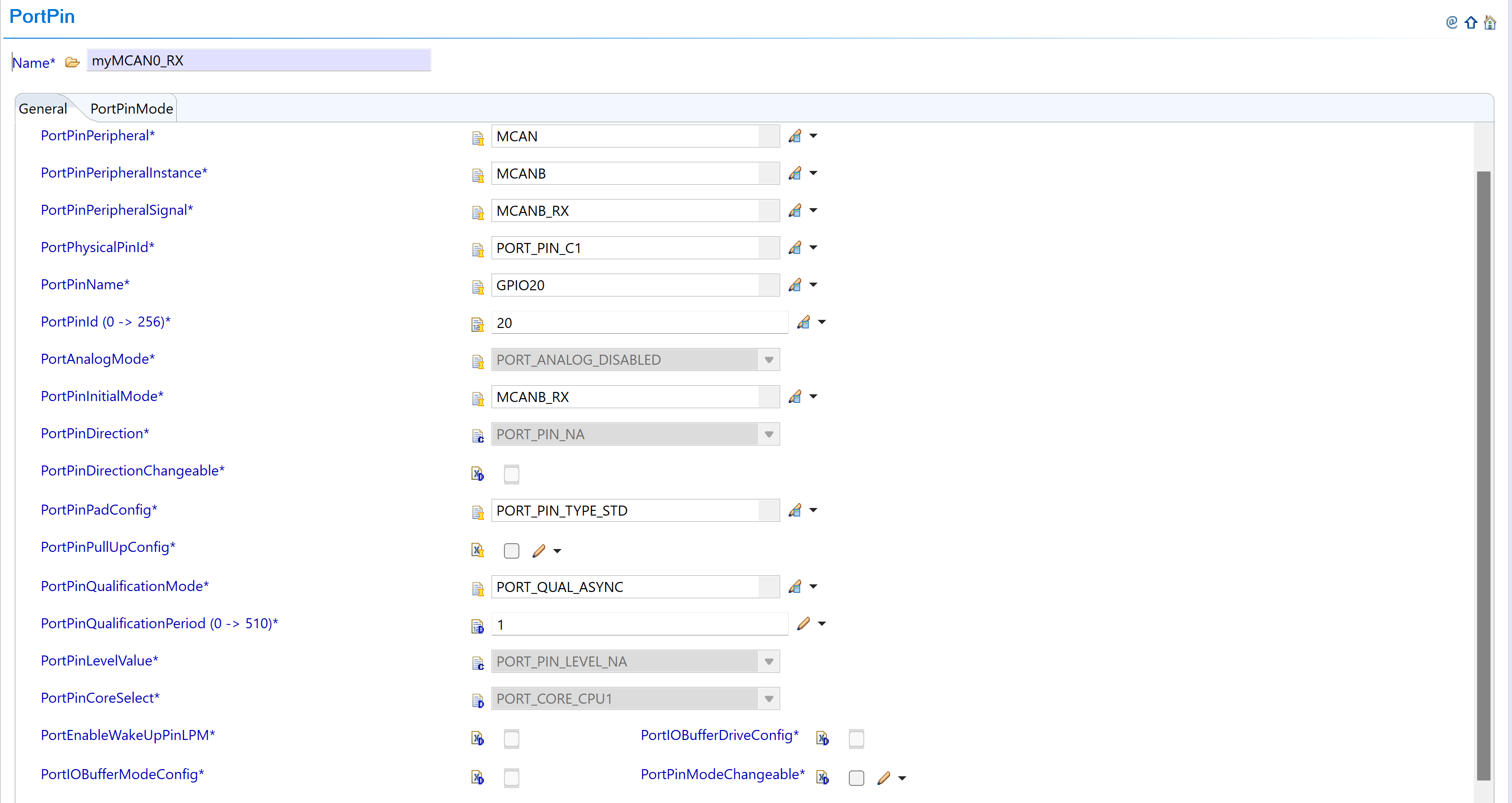
Fig. 5.19 PortPin container - greyed-out parameters are auto-calculated or imported
The reference example described in Reference Example: RA_Example_SysCfgToEbIntegration ships the three importer preferences already wired up, so it can be used as a template for the paths and strategy values required in a new project.
5.1.6. Reference Example: RA_Example_SysCfgToEbIntegration
The MCAL package ships a compile-only reference example named RA_Example_SysCfgToEbIntegration (under examples/RA/ in the MCAL delivery). It is the concrete instance of every abstract concept introduced earlier - the System Integrator authors the SoC allocation once in SysConfig SETUP mode, EB Tresos on CPU1 imports the three ARXMLs, and SysConfig CONFIGURE mode on CPU3 consumes the SETUP .syscfg.
The example targets the F29H85x Q1 variant (F29H859TU-Q1 / F29H859TU8QZEX, package 256ZEX; CCS device string F29H850TU9). It is intentionally a compile-only smoke test - main() only initializes the drivers and spins; no runtime traffic. The intent is to validate that the SETUP → EB Tresos / SETUP → SysConfig CONFIGURE toolchain paths compile end-to-end and produce a single linkable image.
All EB Tresos and SysConfig CONFIGURE-mode outputs are committed in the example folder, so the example builds standalone with zero prior tool runs.
Note
The description in this chapter is deliberately kept concise. Every file mentioned below carries a self-contained comment block that explains the design decisions and back-end details. Refer to the file’s own comments for build-topology, PREBUILD / POSTBUILD merge internals, CCS .projectspec parity notes and other implementation-specific commentary.
5.1.6.1. Folder Layout
The example uses a flat, per-CPU folder structure. All files shared between the two CPUs live at the example root; each CPU’s build unit and generated configuration live under its own subdirectory.
📦f29h85x_mcal
┣ 📂build
┣ 📂docs
┣ 📂drivers
┣ 📂examples
┃ ┣ 📂AppUtils
┃ ┣ 📂Can
┃ ┣ 📂DeviceSupport
┃ ┣ 📂Dio
┃ ┣ 📂Gpt
┃ ┣ 📂Mcu
┃ ┣ 📂Port
┃ ┗ 📂RA
┃ ┃ ┗ 📂RA_Example_SysCfgToEbIntegration
┃ ┃ ┃ ┣ 📂CCS
┃ ┃ ┃ ┃ ┣ 📜RA_Example_SysCfgToEbIntegration_RA.syscfg : SETUP-mode SysCfg (System Integrator input)
┃ ┃ ┃ ┃ ┣ 📜RA_Example_SysCfgToEbIntegration_RA_c29x3.syscfg : CPU3 CONFIGURE-mode SysCfg
┃ ┃ ┃ ┃ ┗ 📜RA_Example_SysCfgToEbIntegration.projectspec : Three CCS project entries (SETUP, CPU1, CPU3)
┃ ┃ ┃ ┣ 📂RA_Example_SysCfgToEbIntegration_RA_SysCfg
┃ ┃ ┃ ┃ ┣ 📜ResourceAllocatorModuleExport.arxml : SETUP-mode ARXML - imported into EB Tresos (RA importer)
┃ ┃ ┃ ┃ ┣ 📜PortModuleExport.arxml : SETUP-mode ARXML - imported into EB Tresos (Port importer)
┃ ┃ ┃ ┃ ┣ 📜McuModuleExport.arxml : SETUP-mode ARXML - imported into EB Tresos (Mcu importer)
┃ ┃ ┃ ┃ ┗ 📜resourceAllocation.json : Reference-only consolidated view of the SETUP allocation
┃ ┃ ┃ ┣ 📂C29x1 : CPU1 - MCAL image
┃ ┃ ┃ ┃ ┣ 📜RA_Example_SysCfgToEbIntegration.c : CPU1 application source
┃ ┃ ┃ ┃ ┣ 📜CMakeLists.txt
┃ ┃ ┃ ┃ ┗ 📂RA_Example_SysCfgToEbIntegration_Config : EB Tresos project - CPU1 CONFIGURE
┃ ┃ ┃ ┃ ┃ ┣ 📂**.prefs** : EB Tresos importer preferences (three SysCfg → EB importers)
┃ ┃ ┃ ┃ ┃ ┣ 📂config
┃ ┃ ┃ ┃ ┃ ┃ ┣ 📜ResourceAllocator.xdm : Committed EB Tresos configuration for the RA module
┃ ┃ ┃ ┃ ┃ ┃ ┣ 📜Mcu.xdm : Committed EB Tresos configuration for the Mcu driver
┃ ┃ ┃ ┃ ┃ ┃ ┣ 📜Port.xdm : Committed EB Tresos configuration for the Port driver
┃ ┃ ┃ ┃ ┃ ┃ ┣ 📜EcuM.xdm
┃ ┃ ┃ ┃ ┃ ┃ ┗ 📜Os.xdm
┃ ┃ ┃ ┃ ┃ ┣ 📂output
┃ ┃ ┃ ┃ ┃ ┃ ┣ 📂include
┃ ┃ ┃ ┃ ┃ ┃ ┃ ┣ 📜Mcu_Cfg.h : Generated pre-compile configuration header for Mcu
┃ ┃ ┃ ┃ ┃ ┃ ┃ ┣ 📜Port_Cfg.h : Generated pre-compile configuration header for Port
┃ ┃ ┃ ┃ ┃ ┃ ┃ ┣ 📜EcuM_Cfg.h
┃ ┃ ┃ ┃ ┃ ┃ ┃ ┗ 📜Os_Cfg.h
┃ ┃ ┃ ┃ ┃ ┃ ┣ 📂src
┃ ┃ ┃ ┃ ┃ ┃ ┃ ┣ 📜Mcu_Cfg.c : Generated configuration source for Mcu (clock, CPUSEL, FRAMESEL tables)
┃ ┃ ┃ ┃ ┃ ┃ ┃ ┣ 📜Port_Cfg.c : Generated configuration source for Port (pin table)
┃ ┃ ┃ ┃ ┃ ┃ ┃ ┣ 📜EcuM_Cfg.c
┃ ┃ ┃ ┃ ┃ ┃ ┃ ┗ 📜Os_Cfg.c
┃ ┃ ┃ ┃ ┃ ┃ ┗ 📂swcd
┃ ┃ ┃ ┃ ┃ ┃ ┃ ┣ 📜Mcu_BSWMD.arxml
┃ ┃ ┃ ┃ ┃ ┃ ┃ ┗ 📜Port_BSWMD.arxml
┃ ┃ ┃ ┃ ┃ ┗ 📜CMakeLists.txt
┃ ┃ ┃ ┣ 📂C29x3 : CPU3 - SDK (driverlib) image
┃ ┃ ┃ ┃ ┣ 📜RA_Example_SysCfgToEbIntegration_RA_c29x3.c : CPU3 application source
┃ ┃ ┃ ┃ ┣ 📜CMakeLists.txt
┃ ┃ ┃ ┃ ┗ 📂RA_Example_SysCfgToEbIntegration_RA_c29x3_SysCfg : SysConfig CONFIGURE-mode generated CPU3 sources
┃ ┃ ┃ ┃ ┃ ┗ 📜CMakeLists.txt
┃ ┃ ┃ ┣ 📜RA_Example_SysCfgToEbIntegration.h : Shared header (documents the tree)
┃ ┃ ┃ ┗ 📜CMakeLists.txt
┃ ┗ 📜CMakeLists.txt
┣ 📂plugins
┣ 📜CMakeLists.txt
┗ 📜CMakePresets.json
Each CMakeLists.txt and each top-of-file source-comment block in the tree above explains the corresponding component in detail. The MCAL / EB Tresos content is concentrated in C29x1/.
5.1.6.2. SETUP Outputs
SETUP mode produces the four files listed below. Their roles were introduced in Hand-off Between Roles; this table shows where each file lands in the example:
Artefact |
Consumer(s) |
Purpose |
|---|---|---|
CCS/RA_Example_SysCfgToEbIntegration_RA.syscfg |
SysConfig CONFIGURE mode on CPU3 (via |
The SETUP allocation itself - the file consumed as input by CONFIGURE mode. |
RA_Example_SysCfgToEbIntegration_RA_SysCfg/ResourceAllocatorModuleExport.arxml |
EB Tresos on CPU1 (RA importer) |
AUTOSAR description of the RA module (device / variant / package, ASysCtl, MCAL and non-MCAL allocations). |
RA_Example_SysCfgToEbIntegration_RA_SysCfg/PortModuleExport.arxml |
EB Tresos on CPU1 (Port importer) |
Pin-muxing decisions and per-pin attributes. |
RA_Example_SysCfgToEbIntegration_RA_SysCfg/McuModuleExport.arxml |
EB Tresos on CPU1 (Mcu importer) |
Clock, PLL, CPUSEL / FRAMESEL bindings, ASysCtl start-up settings. |
RA_Example_SysCfgToEbIntegration_RA_SysCfg/resourceAllocation.json |
Reference / audit only |
Consolidated JSON view of the SETUP allocation. Not consumed as input by any tool. |
The SETUP .syscfg header records the SysConfig invocation used to author the file, including the Q1 part number (a Q1 device is selected because the ARXML export path targets EB Tresos, and MCAL / CDD supports only Q1 devices) and the --enableResourceAllocationSetup flag. Refer to the .syscfg file itself for the exact command line.
5.1.6.3. CPU1 - EB Tresos Path (MCAL)
The CPU1 EB Tresos project lives under C29x1/RA_Example_SysCfgToEbIntegration_Config/ and contains:
config/- the five committed.xdmfiles:ResourceAllocator.xdm,Mcu.xdm,Port.xdm,EcuM.xdm,Os.xdm..prefs/- the three importer preferences that wire the SETUP ARXMLs into EB Tresos:pref_imp_exp_SysCfg_ResourceAllocator_Importer.xdmpref_imp_exp_SysCfg_Port_Importer.xdmpref_imp_exp_SysCfg_Mcu_Importer.xdm
Each of these preference files uses a path relative to the EB Tresos project directory to locate its ARXML in the sibling
RA_Example_SysCfgToEbIntegration_RA_SysCfg/folder. All three useMode=import,ContentType=asc:4.3.1. The per-module Strategy matches the recommendation in Recommended Import Strategy per Module:Strategy=ReplaceforResourceAllocatorandPort(fresh-project import), andStrategy=MergeforMcu(so that the SysConfig-authored device-specific values are layered onto the Recommended Configuration, preserving AUTOSAR-specificMcuparameters that SysConfig does not author). Projects derived from the example that begin hand-editing the EB Tresos configuration forResourceAllocatororPortshould switch those two importers toStrategy=Mergeas well before re-importing, to preserve manual edits (see Re-Import Strategy After Manual Edits).output/{include,src,swcd}/- the committed EB Tresos output:Mcu_Cfg.{c,h},Port_Cfg.{c,h},EcuM_Cfg.{c,h},Os_Cfg.{c,h},Mcu_BSWMD.arxml,Port_BSWMD.arxml.
The CPU1 image (C29x1/RA_Example_SysCfgToEbIntegration.c) is a standard MCAL application: it links the drivers configured by EB Tresos (Mcu, Port, plus the BSW stubs) and calls EcuM_Init(). Refer to the C source file for its README-style doxygen comment, which documents the CPU1 side of the workflow end-to-end.
5.1.6.4. CPU3 - SysConfig CONFIGURE Path (SDK)
The CPU3 image is intentionally SDK-based (driverlib), not MCAL. It exists so that the example exercises the CONFIGURE-mode side of the workflow on a real CPU. Sources:
CCS/RA_Example_SysCfgToEbIntegration_RA_c29x3.syscfg- the CPU3 per-CPU.syscfg.C29x3/RA_Example_SysCfgToEbIntegration_RA_c29x3_SysCfg/- the SysConfig CONFIGURE-mode generated CPU3 sources, wrapped by an INTERFACE library and linked withdriverlib.C29x3/RA_Example_SysCfgToEbIntegration_RA_c29x3.c- the CPU3 entry point.
Both the CPU3 CMakeLists.txt and the CPU3 CCS .projectspec entry pass the SETUP .syscfg to SysConfig via --resourceAllocation, which is what puts SysConfig into CONFIGURE mode.
5.1.6.5. Build Topology (in brief)
Two executables are produced (a CPU1 MCAL image and a CPU3 SDK image), but only one final .out ships: the CPU3 image is merged into the CPU1 image as part of the CPU1 target’s build. This is done via the MCAL PREBUILD / POSTBUILD macros on CMake, and via matching preBuildStep / postBuildStep entries in the CCS .projectspec.
For the exact CMake construction, dependency order, umbrella-target details and per-configuration signing arguments, refer to:
examples/RA/RA_Example_SysCfgToEbIntegration/CMakeLists.txt(umbrella)examples/RA/RA_Example_SysCfgToEbIntegration/C29x1/CMakeLists.txt(CPU1 project)examples/RA/RA_Example_SysCfgToEbIntegration/C29x3/CMakeLists.txt(CPU3 project)examples/RA/RA_Example_SysCfgToEbIntegration/CCS/RA_Example_SysCfgToEbIntegration.projectspec(CCS project spec, three<project>entries)
Each file carries an in-source comment block explaining its role, gating conditions, and merge logic.
Note
CCS build-order caveat. CCS does not enforce inter-project build order. When building this example in CCS, the _c29x3 project must be built manually first (matching the RAM or FLASH configuration to whichever CPU1 configuration is being built) before the _c29x1 project. CMake handles the ordering automatically via add_dependencies().
5.1.7. Reference Material
This chapter groups everything that does not belong in the narrative flow: how the RA plugin ships, recommended-configuration presets, cross-module wiring, non-MCAL peripheral allocation, ASysCtl, the configuration parameter reference, troubleshooting, FAQs, limitations, glossary, references and revision history.
5.1.7.1. Source Files (EB Tresos Plugin Layout)
The Resource Allocator ships as an EB Tresos plugin under plugins/ResourceAllocator_TI_F29H85x/:
📦plugins
┗ 📂ResourceAllocator_TI_F29H85x
┃ ┣ 📂config
┃ ┃ ┣ 📜ResourceAllocator.arxml : ECU Configuration and Parameter definitions
┃ ┃ ┗ 📜ResourceAllocator.xdm : ECU Parameter definition for EB Tresos
┃ ┣ 📂config_ext
┃ ┃ ┣ 📜ResourceAllocator_F29H859DU6_Q_256ZEX_Rec.xdm : Recommended configuration for F29H859DU6_Q_256ZEX
┃ ┃ ┣ 📜ResourceAllocator_F29H859TM8_Q_144RFS_Rec.xdm : Recommended configuration for F29H859TM8_Q_144RFS
┃ ┃ ┣ 📜ResourceAllocator_F29H859TU8_Q_256ZEX_Rec.xdm : Recommended configuration for F29H859TU8_Q_256ZEX
┃ ┃ ┣ 📜ResourceAllocator_F29P329SJ1_Q_144RFS_Rec.xdm : Recommended configuration for F29P329SJ1_Q_144RFS
┃ ┃ ┣ 📜ResourceAllocator_F29P329SM1_Q_144RFS_Rec.xdm : Recommended configuration for F29P329SM1_Q_144RFS
┃ ┃ ┣ 📜ResourceAllocator_F29P329SM2_Q_144RFS_Rec.xdm : Recommended configuration for F29P329SM2_Q_144RFS
┃ ┃ ┣ 📜ResourceAllocator_F29P589DM5_Q_256ZEX_Rec.xdm : Recommended configuration for F29P589DM5_Q_256ZEX
┃ ┃ ┗ 📜ResourceAllocator_F29P589DU5_Q_256ZEX_Rec.xdm : Recommended configuration for F29P589DU5_Q_256ZEX
┃ ┣ 📂META-INF
┃ ┃ ┗ 📜MANIFEST.MF : Plugin manifest and licensing information
┃ ┣ 📂resources : Properties for all devices, variants, packages etc.
┃ ┗ 📜plugin.xml : XML file to register plugin with EB Tresos Studio
5.1.7.2. Recommended Configuration (EB Tresos)
When adding the Resource Allocator plugin to an EB Tresos project directly (i.e., without importing SETUP-mode ARXMLs), users can select a Recommended Configuration as a starting point. This feature provides pre-configured settings for various F29x device variants, simplifying the initial set-up.
5.1.7.2.1. Selecting a Recommended Configuration
In EB Tresos, navigate to Module Configurations.
Add the ResourceAllocator module to your project.
In the Details of “ResourceAllocator” panel, locate the Recommended Configuration dropdown.
Select the appropriate configuration for your target device.
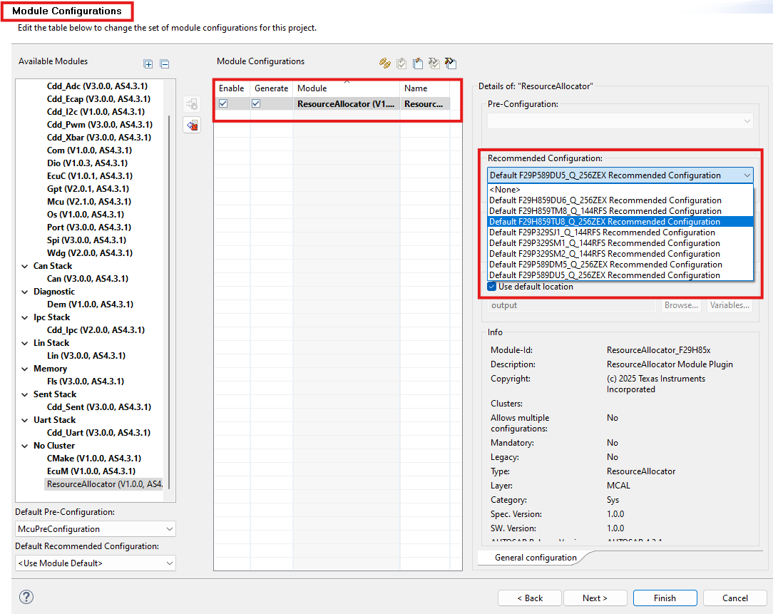
Fig. 5.20 Selecting Recommended Configuration in EB Tresos
5.1.7.3. Integration with Other MCAL Modules
5.1.7.3.1. Dependent Modules
The Resource Allocator is a foundational module with no dependencies on other MCAL modules. It should be configured before other peripheral modules to ensure device-specific settings are available.
5.1.7.3.2. Modules that Reference the Resource Allocator
The following MCAL modules reference the Resource Allocator for device configuration:
Module |
Purpose |
|---|---|
CAN |
Device-specific CAN instance availability |
SPI |
Device-specific SPI instance availability |
LIN |
Device-specific LIN instance availability |
Cdd_Uart |
Device-specific UART instance availability |
Cdd_I2c |
Device-specific I2C instance availability |
Cdd_Sent |
Device-specific SENT instance availability |
Cdd_Adc |
Device-specific ADC instance availability |
Cdd_Pwm |
Device-specific PWM instance availability |
Cdd_Ecap |
Device-specific ECAP instance availability |
Cdd_Xbar |
Device-specific XBAR configuration |
Cdd_Cmpss |
Device-specific CMPSS instance availability |
Mcu |
Device-specific clock and system configuration, CPU ownership and frame assignment for all allocated peripherals (including SDK-managed peripherals) |
Port |
Device-specific pin availability |
5.1.7.3.3. Configuration Workflow (EB Tresos Only)
The following sequence applies when the RA is used directly in EB Tresos (not via SysConfig SETUP mode). This is the traditional pre-RA workflow and is retained for backward compatibility.
Step 1 - Create EB Tresos Project.
Launch EB Tresos Studio.
Create a new configuration project.
Select the target device C2000/F29H85x.
Load the ResourceAllocator plugin.
Step 2 - Configure Device Settings.
Open the ResourceAllocator module configuration.
Navigate to the
ResourceAllocatorGeneralcontainer.Select the appropriate:
ResourceAllocatorDevice(e.g.,F29H85x)ResourceAllocatorVariant(e.g.,F29H859TU_Q1)ResourceAllocatorPackage(e.g.,F29H859TU8_Q_256ZEX)
Run the Auto-Calc wizard in EB Tresos to compute derived values.
Step 3 - Configure Other MCAL Modules.
Add required MCAL modules (CAN, SPI, ADC, etc.).
The modules will reference the device configuration from Resource Allocator.
Configure each module according to application requirements.
Run the Auto-Calc wizard in EB Tresos.
Step 4 - Generate Configuration.
Validate all module configurations.
Generate the configuration files.
The generated code will include device-specific settings.
5.1.7.3.4. Configuration Examples
Example - F29H85x device.
ResourceAllocatorGeneral
├── Device: F29H85x
├── Variant: F29H859TU_Q1
└── Package: F29H859TU8_Q_256ZEX
Result:
All MCAL modules will be configured for the F29H85x device family.
Device-specific peripheral instances will be available.
Appropriate constraints will be applied based on the selected variant.
Example - F29P58x device.
ResourceAllocatorGeneral
├── Device: F29P58x
├── Variant: F29P589DU_Q1
└── Package: F29P589DU5_Q_256ZEX
Result:
All MCAL modules will be configured for the F29P58x device family.
Device-specific peripheral instances will be available.
Appropriate constraints will be applied based on the selected variant.
Note
The Resource Allocator should be configured before other MCAL modules to ensure device-specific settings are available for all module configurations.
Note
The available variants and packages may be updated as new devices are released. Refer to the device-specific datasheet for the most current information.
5.1.7.4. Non-MCAL Peripheral Allocation
The Resource Allocator defines allocation containers for several peripherals that are not supported by TI MCAL or CDD drivers. These peripherals are listed in the table below.
The Resource Allocator entries for these peripherals serve a single purpose: they allow Mcu_Init() to configure the hardware-level CPU ownership (CPUSEL) and peripheral frame assignment (FRAMESEL) registers during system initialization. This ensures that the correct CPU core is granted ownership of each peripheral before any application code runs.
Note
These peripherals are not driven by MCAL APIs. Customers who need to use these peripherals should use the TI F29H85x SDK drivers on the appropriate CPU core. Only CPU1 can write the CPUSEL registers; therefore the Resource Allocator SETUP mode configuration must be performed on CPU1.
Peripheral Container |
Allocated Instance Container |
Description |
|---|---|---|
Eqep |
EqepAllocatedInstance |
Enhanced Quadrature Encoder Pulse (EQEP) instances - CPU ownership and frame assignment configured by Mcu |
Sdfm |
SdfmAllocatedInstance |
Sigma-Delta Filter Module (SDFM) instances - CPU ownership and frame assignment configured by Mcu |
Pmbus |
PmbusAllocatedInstance |
Power Management Bus (PMBus) instances - CPU ownership and frame assignment configured by Mcu |
Dac |
DacAllocatedInstance |
Digital-to-Analog Converter (DAC) instances - CPU ownership and frame assignment configured by Mcu |
Clb |
ClbAllocatedInstance |
Configurable Logic Block (CLB) instances - CPU ownership and frame assignment configured by Mcu |
FsiTx |
FsiTxAllocatedInstance |
Fast Serial Interface Transmit (FSI-TX) instances - CPU ownership and frame assignment configured by Mcu |
FsiRx |
FsiRxAllocatedInstance |
Fast Serial Interface Receive (FSI-RX) instances - CPU ownership and frame assignment configured by Mcu |
Dcc |
DccAllocatedInstance |
Dual Clock Comparator (DCC) instances - CPU ownership and frame assignment configured by Mcu |
Epg |
EpgAllocatedInstance |
Embedded Pattern Generator (EPG) instances - CPU ownership and frame assignment configured by Mcu |
Wadi |
WadiAllocatedInstance |
Windowed Analog-to-Digital Input (WADI) instances - CPU ownership and frame assignment configured by Mcu |
DLTFifoRegs |
DLTFifoRegsAllocatedInstance |
Data Logger Tool FIFO registers - frame assignment configured by Mcu |
Error_Aggregator |
Error_AggregatorAllocatedInstance |
Error Aggregator - frame assignment configured by Mcu |
ESM |
ESMAllocatedInstance |
Error Signaling Module (ESM) - frame assignment configured by Mcu |
Each of these containers follows the same parameter pattern as MCAL-supported peripherals:
Parameter |
Description |
|---|---|
InstanceName |
Identifies the specific hardware instance to be owned by the configured CPU context |
Frame |
Selects the peripheral frame (FRAME0–FRAME3) for memory-mapped register access |
BaseAddr |
Auto-calculated base address macro from |
DebugHaltEnabled |
(where present) Controls DBGHALT signal activation when CPU enters HALT mode |
StandbyModeEnabled |
(where present) Controls peripheral clock gating when CPU enters STANDBY mode |
5.1.7.5. ASysCtl (Analog System Control)
The ASysCtl container centralises all Analog System Control (ASysCtl) hardware configuration for F29x devices. The settings defined here are applied automatically during Mcu_Init() - no additional API calls are required for the start-up configuration.
Note
The ASysCtl container does not allocate a peripheral to a CPU core. It configures analog system control registers that are global to the device.
5.1.7.5.1. TemperatureSensor
Controls the on-chip temperature sensor. The sensor must be enabled before performing temperature-based ADC conversions.
5.1.7.5.2. AnalogReference
Configures the voltage reference source and level for the ADC modules. Each ADC group (A/B and C/D/E) can independently use either an internal reference or an external reference signal. When the internal reference is selected, the reference voltage level (3.3 V or 2.5 V) is also configurable per group.
5.1.7.5.3. VoltageRegulator
Controls the behaviour of the internal analog voltage regulator, including the VMON mask and the option to power down the regulator when an external supply is used.
5.1.7.5.4. BrownOutReset
Configures the Brown-Out Reset Level (BORL) voltage monitor. By default the BORL monitor is enabled and will trigger a reset if the supply voltage drops below the threshold. It can be disabled when the application provides an alternative undervoltage protection mechanism.
5.1.7.5.5. InternalTestNode
Selects the internal signal connected to the analog test bus at start-up. The default selection leaves the test bus disconnected. This setting can also be changed at runtime after Mcu_Init() has completed - refer to the Mcu API guide for the available runtime API.
5.1.7.5.6. CMPSSControl
Each CMPSS instance allocated in the Cdd_Cmpss container has a corresponding CMPSSControl sub-container that configures the analog input mux for the comparator subsystem. The mux selects determine which device signals are routed to the high-side positive (HP), low-side positive (LP), high-side negative (HN), and low-side negative (LN) comparator inputs. The available signal choices are device- and package-specific and are populated automatically based on the device selected in ResourceAllocatorGeneral.
5.1.7.6. Configuration Parameters
The Resource Allocator configuration defines the target device for the MCAL configuration.
5.1.7.6.1. ResourceAllocatorGeneral
Item |
|
|---|---|
Name |
ResourceAllocatorGeneral |
Description |
General configuration (parameters) of the Resource Allocator module. |
Origin |
Texas Instruments |
Post-Build-Variant-Value |
false |
Value-Configuration-Class |
– |
Pre-Compile-Time |
VARIANT-PRE-COMPILE |
Default-value |
false |
Range |
F29H859DU6_Q_100PZS |
5.1.7.6.1.1. Context
Item |
|
|---|---|
Name |
Context |
Description |
This container contains the driver configuration (parameters) for the Context |
Multiplicity-Configuration-Class |
– |
Pre-Compile Time |
VARIANT-PRE-COMPILE |
Origin |
Texas Instruments |
Post-Build-Variant-Value |
false |
Value-Configuration-Class |
– |
Pre-Compile-Time |
VARIANT-PRE-COMPILE |
Default-value |
CPU1 |
Range |
CPU1 |
5.1.7.6.1.2. Can
Configuration container for Context specific settings for the Can module.
5.1.7.6.1.3. CanAllocatedInstance
Item |
|
|---|---|
Name |
CanAllocatedInstance |
Description |
Configuration of a Can instance allocated to this context. |
Multiplicity-Configuration-Class |
– |
Pre-Compile Time |
VARIANT-PRE-COMPILE |
Post-build-variant-multiplicity |
false |
Origin |
Texas Instruments |
Post-Build-Variant-Value |
false |
Value-Configuration-Class |
– |
Pre-Compile-Time |
VARIANT-PRE-COMPILE |
Default-value |
MCANA_DRIVER_BASE_FRAME(0U) |
Range |
FRAME0 |
5.1.7.6.1.4. Spi
Configuration container for Context specific settings for the Spi module.
5.1.7.6.1.5. SpiAllocatedInstance
Item |
|
|---|---|
Name |
SpiAllocatedInstance |
Description |
Configuration for Spi Instance. |
Multiplicity-Configuration-Class |
– |
Pre-Compile Time |
VARIANT-PRE-COMPILE |
Post-build-variant-multiplicity |
false |
Origin |
Texas Instruments |
Post-Build-Variant-Value |
false |
Value-Configuration-Class |
– |
Pre-Compile-Time |
VARIANT-PRE-COMPILE |
Default-value |
SPIA_BASE_FRAME(0U) |
Range |
FRAME0 |
5.1.7.6.1.6. Lin
Configuration container for Context specific settings for the Lin module.
5.1.7.6.1.7. LinAllocatedInstance
Item |
|
|---|---|
Name |
LinAllocatedInstance |
Description |
Configuration for Lin Instance. |
Multiplicity-Configuration-Class |
– |
Pre-Compile Time |
VARIANT-PRE-COMPILE |
Post-build-variant-multiplicity |
false |
Origin |
Texas Instruments |
Post-Build-Variant-Value |
false |
Value-Configuration-Class |
– |
Pre-Compile-Time |
VARIANT-PRE-COMPILE |
Default-value |
LINA_BASE_FRAME(0U) |
Range |
FRAME0 |
5.1.7.6.1.8. Cdd_Adc
Configuration container for Context specific settings for the Cdd_Adc module.
5.1.7.6.1.9. Cdd_AdcAllocatedInstance
Item |
|
|---|---|
Name |
Cdd_AdcAllocatedInstance |
Description |
Configuration for Cdd_Adc Instance. |
Multiplicity-Configuration-Class |
– |
Pre-Compile Time |
VARIANT-PRE-COMPILE |
Post-build-variant-multiplicity |
false |
Origin |
Texas Instruments |
Post-Build-Variant-Value |
false |
Value-Configuration-Class |
– |
Pre-Compile-Time |
VARIANT-PRE-COMPILE |
Default-value |
ADCA_BASE_FRAME(0U) |
Range |
FRAME0 |
5.1.7.6.1.10. CddAdcSafetyCheckerInstance
Item |
|
|---|---|
Name |
CddAdcSafetyCheckerInstance |
Description |
Configuration of ADC safety checker instances. |
Multiplicity-Configuration-Class |
– |
Pre-Compile Time |
VARIANT-PRE-COMPILE |
Post-build-variant-multiplicity |
false |
Origin |
Texas Instruments |
Post-Build-Variant-Value |
false |
Value-Configuration-Class |
– |
Pre-Compile-Time |
VARIANT-PRE-COMPILE |
Default-value |
ADCSAFETYCHECK1_BASE_FRAME(0U) |
Range |
FRAME0 |
5.1.7.6.1.11. CddAdcCheckerInterruptEvtInstance
Item |
|
|---|---|
Name |
CddAdcCheckerInterruptEvtInstance |
Description |
Configuration of ADC safety checker interrupt event instances. |
Multiplicity-Configuration-Class |
– |
Pre-Compile Time |
VARIANT-PRE-COMPILE |
Post-build-variant-multiplicity |
false |
Origin |
Texas Instruments |
Post-Build-Variant-Value |
false |
Value-Configuration-Class |
– |
Pre-Compile-Time |
VARIANT-PRE-COMPILE |
Default-value |
ADCSAFETYCHECKINTEVT1_BASE_FRAME(0U) |
Range |
FRAME0 |
5.1.7.6.1.12. CddAdcGlobalSoftwareForce
Item |
|
|---|---|
Name |
CddAdcGlobalSoftwareForce |
Description |
Configuration of global software force. This is linked to global software trigger feature in ADC. This should be added only once. |
Multiplicity-Configuration-Class |
– |
Pre-Compile Time |
VARIANT-PRE-COMPILE |
Post-build-variant-multiplicity |
false |
Origin |
Texas Instruments |
Post-Build-Variant-Value |
false |
Value-Configuration-Class |
– |
Pre-Compile-Time |
VARIANT-PRE-COMPILE |
Default-value |
ADCGLOBAL_BASE_FRAME(0U) |
Range |
FRAME0 |
5.1.7.6.1.13. Cdd_Ecap
Configuration container for Context specific settings for the Cdd_Ecap module.
5.1.7.6.1.14. Cdd_EcapAllocatedInstance
Item |
|
|---|---|
Name |
Cdd_EcapAllocatedInstance |
Description |
Configuration for Cdd_Ecap Instance. |
Multiplicity-Configuration-Class |
– |
Pre-Compile Time |
VARIANT-PRE-COMPILE |
Post-build-variant-multiplicity |
false |
Origin |
Texas Instruments |
Post-Build-Variant-Value |
false |
Value-Configuration-Class |
– |
Pre-Compile-Time |
VARIANT-PRE-COMPILE |
Default-value |
ECAP1_BASE_FRAME(0U) |
Range |
FRAME0 |
5.1.7.6.1.15. Cdd_Dma
Configuration container for Context specific settings for the Cdd_Dma module. This container defines which DMA channels are assigned to this specific CPU context.
5.1.7.6.1.16. CddDmaAllocatedChannel
Item |
|
|---|---|
Name |
CddDmaAllocatedChannel |
Description |
Configuration of a DMA channel allocated to this CPU context. Each allocated channel can only be used by this context.. |
Multiplicity-Configuration-Class |
– |
Pre-Compile Time |
VARIANT-PRE-COMPILE |
Post-build-variant-multiplicity |
false |
Origin |
Texas Instruments |
Post-Build-Variant-Value |
false |
Value-Configuration-Class |
– |
Pre-Compile-Time |
VARIANT-PRE-COMPILE |
5.1.7.6.1.17. Cdd_I2c
Configuration container for Context specific settings for the Cdd_I2c module.
5.1.7.6.1.18. Cdd_I2cAllocatedInstance
Item |
|
|---|---|
Name |
Cdd_I2cAllocatedInstance |
Description |
Configuration for Cdd_I2c Instance. |
Multiplicity-Configuration-Class |
– |
Pre-Compile Time |
VARIANT-PRE-COMPILE |
Post-build-variant-multiplicity |
false |
Origin |
Texas Instruments |
Post-Build-Variant-Value |
false |
Value-Configuration-Class |
– |
Pre-Compile-Time |
VARIANT-PRE-COMPILE |
Default-value |
I2CA_BASE_FRAME(0U) |
Range |
FRAME0 |
5.1.7.6.1.19. Cdd_Pwm
Configuration container for Context specific settings for the Cdd_Pwm module.
5.1.7.6.1.20. Cdd_PwmAllocatedInstance
Item |
|
|---|---|
Name |
Cdd_PwmAllocatedInstance |
Description |
Configuration for Cdd_Pwm Instance. |
Multiplicity-Configuration-Class |
– |
Pre-Compile Time |
VARIANT-PRE-COMPILE |
Post-build-variant-multiplicity |
false |
Origin |
Texas Instruments |
Post-Build-Variant-Value |
false |
Value-Configuration-Class |
– |
Pre-Compile-Time |
VARIANT-PRE-COMPILE |
Default-value |
EPWM1XLINK_BASE_FRAME(0U) |
Range |
FRAME0 |
5.1.7.6.1.21. CddPwmHrpwmCalInstance
Item |
|
|---|---|
Name |
CddPwmHrpwmCalInstance |
Description |
Configuration of Hrpwm calibration instances. |
Multiplicity-Configuration-Class |
– |
Pre-Compile Time |
VARIANT-PRE-COMPILE |
Post-build-variant-multiplicity |
false |
Origin |
Texas Instruments |
Post-Build-Variant-Value |
false |
Value-Configuration-Class |
– |
Pre-Compile-Time |
VARIANT-PRE-COMPILE |
Default-value |
HRPWMCAL1_BASE_FRAME(0U) |
Range |
FRAME0 |
5.1.7.6.1.22. Cdd_Sent
Configuration container for Context specific settings for the Cdd_Sent module.
5.1.7.6.1.23. Cdd_SentAllocatedInstance
Item |
|
|---|---|
Name |
Cdd_SentAllocatedInstance |
Description |
Configuration of a Cdd_Sent instance allocated to this context. |
Multiplicity-Configuration-Class |
– |
Pre-Compile Time |
VARIANT-PRE-COMPILE |
Post-build-variant-multiplicity |
false |
Origin |
Texas Instruments |
Post-Build-Variant-Value |
false |
Value-Configuration-Class |
– |
Pre-Compile-Time |
VARIANT-PRE-COMPILE |
Default-value |
SENT1_BASE_FRAME(0U) |
Range |
FRAME0 |
5.1.7.6.1.24. Cdd_Uart
Configuration container for Context specific settings for the Cdd_Uart module.
5.1.7.6.1.25. Cdd_UartAllocatedInstance
Item |
|
|---|---|
Name |
Cdd_UartAllocatedInstance |
Description |
Configuration of a Cdd_Uart instance allocated to this context. |
Multiplicity-Configuration-Class |
– |
Pre-Compile Time |
VARIANT-PRE-COMPILE |
Post-build-variant-multiplicity |
false |
Origin |
Texas Instruments |
Post-Build-Variant-Value |
false |
Value-Configuration-Class |
– |
Pre-Compile-Time |
VARIANT-PRE-COMPILE |
Default-value |
UARTA_BASE_FRAME(0U) |
Range |
FRAME0 |
5.1.7.6.1.26. Cdd_Cmpss
Configuration container for Context specific settings for the Cdd_Cmpss module.
5.1.7.6.1.27. Cdd_CmpssAllocatedInstance
Item |
|
|---|---|
Name |
Cdd_CmpssAllocatedInstance |
Description |
Configuration of a Cdd_Cmpss instance allocated to this context. |
Multiplicity-Configuration-Class |
– |
Pre-Compile Time |
VARIANT-PRE-COMPILE |
Post-build-variant-multiplicity |
false |
Origin |
TI_F29H85x |
Post-Build-Variant-Value |
false |
Value-Configuration-Class |
– |
Pre-Compile-Time |
VARIANT-PRE-COMPILE |
Default-value |
CMPSS_NEG_INPUT_SIGNAL_MUX0_AIO161 |
Range |
CMPSS_NEG_INPUT_SIGNAL_MUX0_AIO161 |
5.1.7.6.1.28. Eqep
Configuration container for Context specific settings for the Eqep module.
5.1.7.6.1.29. EqepAllocatedInstance
Item |
|
|---|---|
Name |
EqepAllocatedInstance |
Description |
Configuration of a Eqep instance allocated to this context. |
Multiplicity-Configuration-Class |
– |
Pre-Compile Time |
VARIANT-PRE-COMPILE |
Post-build-variant-multiplicity |
false |
Origin |
Texas Instruments |
Post-Build-Variant-Value |
false |
Value-Configuration-Class |
– |
Pre-Compile-Time |
VARIANT-PRE-COMPILE |
Default-value |
EQEP1_BASE_FRAME(0U) |
Range |
FRAME0 |
5.1.7.6.1.30. Sdfm
Configuration container for Context specific settings for the Sdfm module.
5.1.7.6.1.31. SdfmAllocatedInstance
Item |
|
|---|---|
Name |
SdfmAllocatedInstance |
Description |
Configuration of a Sdfm instance allocated to this context. |
Multiplicity-Configuration-Class |
– |
Pre-Compile Time |
VARIANT-PRE-COMPILE |
Post-build-variant-multiplicity |
false |
Origin |
Texas Instruments |
Post-Build-Variant-Value |
false |
Value-Configuration-Class |
– |
Pre-Compile-Time |
VARIANT-PRE-COMPILE |
Default-value |
SDFM1_BASE_FRAME(0U) |
Range |
FRAME0 |
5.1.7.6.1.32. Pmbus
Configuration container for Context specific settings for the Pmbus module.
5.1.7.6.1.33. PmbusAllocatedInstance
Item |
|
|---|---|
Name |
PmbusAllocatedInstance |
Description |
Configuration of a Pmbus instance allocated to this context. |
Multiplicity-Configuration-Class |
– |
Pre-Compile Time |
VARIANT-PRE-COMPILE |
Post-build-variant-multiplicity |
false |
Origin |
Texas Instruments |
Post-Build-Variant-Value |
false |
Value-Configuration-Class |
– |
Pre-Compile-Time |
VARIANT-PRE-COMPILE |
Default-value |
PMBUSA_BASE_FRAME(0U) |
Range |
FRAME0 |
5.1.7.6.1.34. Dac
Configuration container for Context specific settings for the Dac module.
5.1.7.6.1.35. DacAllocatedInstance
Item |
|
|---|---|
Name |
DacAllocatedInstance |
Description |
Configuration of a Dac instance allocated to this context. |
Multiplicity-Configuration-Class |
– |
Pre-Compile Time |
VARIANT-PRE-COMPILE |
Post-build-variant-multiplicity |
false |
Origin |
Texas Instruments |
Post-Build-Variant-Value |
false |
Value-Configuration-Class |
– |
Pre-Compile-Time |
VARIANT-PRE-COMPILE |
Default-value |
DACA_BASE_FRAME(0U) |
Range |
FRAME0 |
5.1.7.6.1.36. Clb
Configuration container for Context specific settings for the Clb module.
5.1.7.6.1.37. ClbAllocatedInstance
Item |
|
|---|---|
Name |
ClbAllocatedInstance |
Description |
Configuration of a Clb instance allocated to this context. |
Multiplicity-Configuration-Class |
– |
Pre-Compile Time |
VARIANT-PRE-COMPILE |
Post-build-variant-multiplicity |
false |
Origin |
Texas Instruments |
Post-Build-Variant-Value |
false |
Value-Configuration-Class |
– |
Pre-Compile-Time |
VARIANT-PRE-COMPILE |
Default-value |
CLB1_BASE_FRAME(0U) |
Range |
FRAME0 |
5.1.7.6.1.38. FsiTx
Configuration container for Context specific settings for the FsiTx module.
5.1.7.6.1.39. FsiTxAllocatedInstance
Item |
|
|---|---|
Name |
FsiTxAllocatedInstance |
Description |
Configuration of a FsiTx instance allocated to this context. |
Multiplicity-Configuration-Class |
– |
Pre-Compile Time |
VARIANT-PRE-COMPILE |
Post-build-variant-multiplicity |
false |
Origin |
Texas Instruments |
Post-Build-Variant-Value |
false |
Value-Configuration-Class |
– |
Pre-Compile-Time |
VARIANT-PRE-COMPILE |
Default-value |
FSITXA_BASE_FRAME(0U) |
Range |
FRAME0 |
5.1.7.6.1.40. FsiRx
Configuration container for Context specific settings for the FsiRx module.
5.1.7.6.1.41. FsiRxAllocatedInstance
Item |
|
|---|---|
Name |
FsiRxAllocatedInstance |
Description |
Configuration of a FsiRx instance allocated to this context. |
Multiplicity-Configuration-Class |
– |
Pre-Compile Time |
VARIANT-PRE-COMPILE |
Post-build-variant-multiplicity |
false |
Origin |
Texas Instruments |
Post-Build-Variant-Value |
false |
Value-Configuration-Class |
– |
Pre-Compile-Time |
VARIANT-PRE-COMPILE |
Default-value |
FSIRXA_BASE_FRAME(0U) |
Range |
FRAME0 |
5.1.7.6.1.42. Dcc
Configuration container for Context specific settings for the Dcc module.
5.1.7.6.1.43. DccAllocatedInstance
Item |
|
|---|---|
Name |
DccAllocatedInstance |
Description |
Configuration of a Dcc instance allocated to this context. |
Multiplicity-Configuration-Class |
– |
Pre-Compile Time |
VARIANT-PRE-COMPILE |
Post-build-variant-multiplicity |
false |
Origin |
Texas Instruments |
Post-Build-Variant-Value |
false |
Value-Configuration-Class |
– |
Pre-Compile-Time |
VARIANT-PRE-COMPILE |
Default-value |
DCC1_BASE_FRAME(0U) |
Range |
FRAME0 |
5.1.7.6.1.44. Epg
Configuration container for Context specific settings for the Epg module.
5.1.7.6.1.45. EpgAllocatedInstance
Item |
|
|---|---|
Name |
EpgAllocatedInstance |
Description |
Configuration of a Epg instance allocated to this context. |
Multiplicity-Configuration-Class |
– |
Pre-Compile Time |
VARIANT-PRE-COMPILE |
Post-build-variant-multiplicity |
false |
Origin |
Texas Instruments |
Post-Build-Variant-Value |
false |
Value-Configuration-Class |
– |
Pre-Compile-Time |
VARIANT-PRE-COMPILE |
Default-value |
FRAME0 |
Range |
FRAME0 |
5.1.7.6.1.46. Wadi
Configuration container for Context specific settings for the Wadi module.
5.1.7.6.1.47. WadiAllocatedInstance
Item |
|
|---|---|
Name |
WadiAllocatedInstance |
Description |
Configuration of a Wadi instance allocated to this context. |
Multiplicity-Configuration-Class |
– |
Pre-Compile Time |
VARIANT-PRE-COMPILE |
Post-build-variant-multiplicity |
false |
Origin |
Texas Instruments |
Post-Build-Variant-Value |
false |
Value-Configuration-Class |
– |
Pre-Compile-Time |
VARIANT-PRE-COMPILE |
Default-value |
FRAME0 |
Range |
FRAME0 |
5.1.7.6.1.48. ASysCtl
Configuration container for ASysCtl (Analog System Control) module. Controls analog subsystem initialization including temperature sensor, analog reference, voltage regulator, brown-out reset, internal test node, and CMPSS mux configuration.
5.1.7.6.1.49. TemperatureSensor
Item |
|
|---|---|
Name |
TemperatureSensor |
Description |
Configuration for the on-chip temperature sensor (TSNSCTL register). |
Origin |
Texas Instruments |
Post-Build-Variant-Value |
false |
Value-Configuration-Class |
– |
Pre-Compile-Time |
VARIANT-PRE-COMPILE |
Default-value |
false |
5.1.7.6.1.50. AnalogReference
Item |
|
|---|---|
Name |
AnalogReference |
Description |
Configuration for the analog reference control (ANAREFCTL register). Controls ADC reference source and voltage range for ADC-A/B and ADC-C/D/E groups. |
Origin |
Texas Instruments |
Post-Build-Variant-Value |
false |
Value-Configuration-Class |
– |
Pre-Compile-Time |
VARIANT-PRE-COMPILE |
Default-value |
REFERENCE_3_3V |
Range |
REFERENCE_3_3V |
5.1.7.6.1.51. VoltageRegulator
Item |
|
|---|---|
Name |
VoltageRegulator |
Description |
Configuration for the internal voltage regulator (VREGCTL register). |
Origin |
Texas Instruments |
Post-Build-Variant-Value |
false |
Value-Configuration-Class |
– |
Pre-Compile-Time |
VARIANT-PRE-COMPILE |
Default-value |
false |
5.1.7.6.1.52. BrownOutReset
Item |
|
|---|---|
Name |
BrownOutReset |
Description |
Configuration for Brown-Out Reset Level (VMONCTL register). |
Origin |
Texas Instruments |
Post-Build-Variant-Value |
false |
Value-Configuration-Class |
– |
Pre-Compile-Time |
VARIANT-PRE-COMPILE |
Default-value |
false |
5.1.7.6.1.53. InternalTestNode
Item |
|
|---|---|
Name |
InternalTestNode |
Description |
Configuration for the internal analog test node (INTERNALTESTCTL register). Key-protection sequence is applied automatically. |
Origin |
Texas Instruments |
Post-Build-Variant-Value |
false |
Value-Configuration-Class |
– |
Pre-Compile-Time |
VARIANT-PRE-COMPILE |
Default-value |
MCU_ASYSCTL_TEST_NODE_NO_CONN |
Range |
MCU_ASYSCTL_TEST_NODE_NO_CONN |
5.1.7.6.1.54. Cdd_Xbar
Configuration container for Cdd_Xbar module.
5.1.7.6.1.55. CddXbarOutputXbarFlag
Item |
|
|---|---|
Name |
CddXbarOutputXbarFlag |
Description |
Configuration of a Cdd Xbar Output Xbar flag. |
Multiplicity-Configuration-Class |
– |
Pre-Compile Time |
VARIANT-PRE-COMPILE |
Post-build-variant-multiplicity |
false |
Origin |
Texas Instruments |
Post-Build-Variant-Value |
false |
Value-Configuration-Class |
– |
Pre-Compile-Time |
VARIANT-PRE-COMPILE |
Default-value |
OUTPUTXBAR1_FLAGS_BASE_FRAME(0U) |
Range |
FRAME0 |
5.1.7.6.1.56. CddXbarInputFlag
Item |
|
|---|---|
Name |
CddXbarInputFlag |
Description |
Configuration of a Cdd_Xbar Input flags. |
Multiplicity-Configuration-Class |
– |
Pre-Compile Time |
VARIANT-PRE-COMPILE |
Post-build-variant-multiplicity |
false |
Origin |
Texas Instruments |
Post-Build-Variant-Value |
false |
Value-Configuration-Class |
– |
Pre-Compile-Time |
VARIANT-PRE-COMPILE |
Default-value |
XBAR_BASE_FRAME(0U) |
Range |
FRAME0 |
5.1.7.6.1.57. Cdd_Dma
Configuration container for the Cdd_Dma module hardware resources. This defines the available RTDMA hardware instances and their channels that can be allocated to different CPU contexts in the system.
5.1.7.6.1.58. CddDmaHwInstance
Item |
|
|---|---|
Name |
CddDmaHwInstance |
Description |
Configuration of a RTDMA hardware instance. Each instance represents a physical RTDMA peripheral with its own set of channels. Multiple instances can be configured if the device supports multiple RTDMA peripherals. |
Multiplicity-Configuration-Class |
– |
Pre-Compile Time |
VARIANT-PRE-COMPILE |
Post-build-variant-multiplicity |
false |
Origin |
Texas Instruments |
Post-Build-Variant-Value |
false |
Value-Configuration-Class |
– |
Pre-Compile-Time |
VARIANT-PRE-COMPILE |
Default-value |
false |
Range |
CDD_DMA_EMULATION_STOP |
5.1.7.6.1.59. CddDmaMpuRegion
Item |
|
|---|---|
Name |
CddDmaMpuRegion |
Description |
Configuration container for a DMA Memory Protection Unit (MPU) region. Each MPU region defines a protected memory address range with specific access permissions (read/write/no access) for selected DMA channels. |
Multiplicity-Configuration-Class |
– |
Pre-Compile Time |
VARIANT-PRE-COMPILE |
Post-build-variant-multiplicity |
false |
Origin |
Texas Instruments |
Post-Build-Variant-Value |
false |
Value-Configuration-Class |
– |
Pre-Compile-Time |
VARIANT-PRE-COMPILE |
Default-value |
CDD_DMA_NO_ACCESS |
Range |
CDD_DMA_NO_ACCESS |
Max-value |
4294967295 |
Min-value |
0 |
5.1.7.6.1.60. CddDmaChannel
Item |
|
|---|---|
Name |
CddDmaChannel |
Description |
Configuration of a DMA channel within this RTDMA hardware instance. Each channel represents an independent DMA transfer engine that can move data between memory and peripherals. This container defines all available channels (e.g., CH1, CH2, …, CH10) for the instance, which can then be allocated to specific CPU contexts. |
Multiplicity-Configuration-Class |
– |
Pre-Compile Time |
VARIANT-PRE-COMPILE |
Post-build-variant-multiplicity |
false |
Origin |
Texas Instruments |
Post-Build-Variant-Value |
false |
Value-Configuration-Class |
– |
Pre-Compile-Time |
VARIANT-PRE-COMPILE |
Default-value |
1 |
Range |
CH1 |
Max-value |
3 |
Min-value |
0 |
5.1.7.6.1.61. DLTFifoRegs
Configuration container for DLTFifoRegs module.
5.1.7.6.1.62. DLTFifoRegsAllocatedInstance
Item |
|
|---|---|
Name |
DLTFifoRegsAllocatedInstance |
Description |
Configuration of a DLTFifoRegs instance. |
Multiplicity-Configuration-Class |
– |
Pre-Compile Time |
VARIANT-PRE-COMPILE |
Post-build-variant-multiplicity |
false |
Origin |
Texas Instruments |
Post-Build-Variant-Value |
false |
Value-Configuration-Class |
– |
Pre-Compile-Time |
VARIANT-PRE-COMPILE |
Default-value |
FRAME0 |
Range |
FRAME0 |
5.1.7.6.1.63. Error_Aggregator
Configuration container for Error_Aggregator module.
5.1.7.6.1.64. Error_AggregatorAllocatedInstance
Item |
|
|---|---|
Name |
Error_AggregatorAllocatedInstance |
Description |
Configuration of a Error_Aggregator instance. |
Multiplicity-Configuration-Class |
– |
Pre-Compile Time |
VARIANT-PRE-COMPILE |
Post-build-variant-multiplicity |
false |
Origin |
Texas Instruments |
Post-Build-Variant-Value |
false |
Value-Configuration-Class |
– |
Pre-Compile-Time |
VARIANT-PRE-COMPILE |
Default-value |
ERRORAGGREGATOR_BASE_FRAME(0U) |
Range |
FRAME0 |
5.1.7.6.1.65. ESM
Configuration container for ESM module.
5.1.7.6.1.66. ESMAllocatedInstance
Item |
|
|---|---|
Name |
ESMAllocatedInstance |
Description |
Configuration of a ESM instance. |
Multiplicity-Configuration-Class |
– |
Pre-Compile Time |
VARIANT-PRE-COMPILE |
Post-build-variant-multiplicity |
false |
Origin |
Texas Instruments |
Post-Build-Variant-Value |
false |
Value-Configuration-Class |
– |
Pre-Compile-Time |
VARIANT-PRE-COMPILE |
Default-value |
ESM |
Range |
ESM |
5.1.7.6.1.67. ESM
Item |
|
|---|---|
Name |
ESM |
Origin |
Texas Instruments |
Description |
Selects the peripheral frame. Frames enable simultaneous access from different initiators to peripherals without arbitration stalls, each with its own base address. |
Post-Build-Variant-Value |
false |
Value-Configuration-Class |
– |
Pre-Compile-Time |
VARIANT-PRE-COMPILE |
Default-value |
FRAME0 |
Range |
FRAME0 |
5.1.7.7. Troubleshooting
5.1.7.7.1. EB Tresos Import Fails: Cannot Resolve ARXML Path
Symptom: The three importer preferences under
.prefs/fail to locate their*ModuleExport.arxmlfiles.Cause: The importer path is relative to the EB Tresos project folder. If the SETUP artefacts are not in the expected sibling
..._RA_SysCfg/directory (two levels up from.prefs/), the import silently fails.Resolution: Ensure the SETUP artefacts are committed under
<example-root>/<example-name>_RA_SysCfg/with the exact filenamesResourceAllocatorModuleExport.arxml,PortModuleExport.arxml,McuModuleExport.arxml. Check theFileNamevalue in eachpref_imp_exp_SysCfg_*_Importer.xdmmatches your actual project’s relative depth.
5.1.7.7.2. ARXML Files Are Not Produced on a Non-Q1 Device
Symptom: SysConfig SETUP mode runs on a non-Q1 device, but the three
*ModuleExport.arxmlfiles are not produced (only the SETUP.syscfgandresourceAllocation.jsonappear).Cause: SysConfig gates the ARXML export to Q1 devices because MCAL / CDD (EB Tresos) supports only Q1 variants. SETUP mode itself runs on any supported device, but the ARXML generation is intentionally suppressed off-Q1.
Resolution: To use the EB Tresos import path, select a Q1 part number (for example
F29H859TU8QZEX, CCS device stringF29H850TU9) in the SETUP.syscfgand re-run SETUP mode. Non-Q1 device targets can still use the CONFIGURE-mode.syscfghand-off for their SDK cores; they simply cannot feed an EB Tresos project.
5.1.7.7.3. CCS Builds the CPU1 Project but Cannot Find the CPU3 .bin
Symptom: In CCS, building the
_c29x1project fails duringpreBuildStepcomplaining about a missing..._c29x3.bin.Cause: CCS does not enforce inter-project build order. The CPU3 project must be built manually first in the matching configuration (CPU3_RAM before CPU1_RAM, CPU3_FLASH before CPU1_FLASH).
Resolution: Right-click the
_c29x3project → Build Configurations → Build, then build the_c29x1project. CMake handles this automatically viaadd_dependencies().
5.1.7.7.4. SysConfig Version Mismatch in CONFIGURE Mode
Symptom: CONFIGURE-mode SysConfig warns about or misparses fields when opening a per-CPU
.syscfgwith a SETUP.syscfgauthored by a different tool version.Cause: Both the SETUP
.syscfgheader and the referenceresourceAllocation.jsonrecord the SysConfig version used to author them. Loading with a different version can yield unpredictable behaviour.Resolution: Use the same SysConfig version for CONFIGURE mode as was used for SETUP mode. The version is recorded in the SETUP
.syscfgheader (see the@versionsline) and in the reference JSON.
5.1.7.8. Frequently Asked Questions
Q. Do all cores’ SysConfig files need to be open at the same time?
No. That was the pre-RA behaviour. With RA, once SETUP mode has produced its outputs (the SETUP .syscfg + the three ARXMLs), each CPU can be configured completely independently - the MCAL side from the ARXMLs, the SDK side from the SETUP .syscfg.
Q. Is RA mandatory? No. STANDARD mode is still the default on device power-on for SysConfig, and is still supported by MCAL. RA is opt-in.
Q. Will my generated code change if I move from STANDARD to RA mode? No changes are expected in the generated code for equivalent input allocations. RA is a work-flow change, not a code-generation change.
Q. Can I make an RA-locked EB Tresos parameter editable again? Yes. EB Tresos provides an override option for customers who do not want to use the SysConfig-based flow. See EB Tresos preferences for the RA importers.
Q. Can I migrate an existing STANDARD project to RA? Not programmatically in the current release. Create a new project (or modify the existing project) that uses RA from the start.
Q. Can I migrate from RA back to STANDARD? Not supported. Settings that only exist in the SETUP view would be lost. Reverse migration is not planned.
Q. Which CPU authors CPUSEL?
Only CPU1 can write the CPUSEL registers. Therefore SETUP-mode configuration must be applied by CPU1’s Mcu_Init() at run-time. This is why every non-MCAL peripheral allocation still lives in the RA - so Mcu_Init() can program CPUSEL/FRAMESEL for the whole device before any core’s application code runs.
Q. What is the AUTOSAR release supported by the plugin?
AUTOSAR 4.3.1 (matches the ContentType in the importer preferences).
5.1.7.9. Limitations
ARXML generation is Q1-only. SysConfig SETUP mode itself runs on any supported F29x device, but the three
*ModuleExport.arxmlfiles consumed by EB Tresos are emitted only when the SETUP context targets a Q1 device. This mirrors the MCAL / CDD scope (Q1-only). Non-Q1 device targets can still use the CONFIGURE-mode hand-off on their SDK cores.Compile-only reference example.
RA_Example_SysCfgToEbIntegration(see Reference Example: RA_Example_SysCfgToEbIntegration) is a compile-only smoke test.main()does not exercise any driver runtime API; no transmissions, interrupts or notifications occur. It validates the toolchain path, not register-level correctness.CCS build order is manual. CCS has no built-in inter-project build-order setting. The CPU3 project must be built manually before the CPU1 project (matching RAM/FLASH configurations).
STANDARD ↔ RA migration. Not supported in either direction in the current release.
Tabular summary views deferred. The “Memory Region Summary” and “SSU Summary” tabular views are not yet available in SETUP mode; support is planned for a future release.
Memory Region / System Security / LINK / STACK UI in CONFIGURE mode. These modules are not yet directly available in the CONFIGURE-mode UI. Associated code is still auto-generated on all applicable cores from the SETUP allocation. UI support is planned for a future release. The
Sectionsmodule is available in CONFIGURE mode.Non-MCAL peripherals. The peripherals listed in Non-MCAL Peripheral Allocation are not driven by MCAL APIs - the RA entries exist only to let
Mcu_Init()configure CPUSEL/FRAMESEL. Customer applications must use the F29H85x SDK drivers on the appropriate CPU to actually drive those peripherals.
5.1.7.10. References
Reference example (shipped with the MCAL delivery):
RA_Example_SysCfgToEbIntegration- see Reference Example: RA_Example_SysCfgToEbIntegration.
EB Tresos plugin (shipped with the MCAL delivery):
plugins/ResourceAllocator_TI_F29H85x/
SDK documentation (SysConfig side of the RA workflow):
Related module user guides:
Migration guide: