TI-RTOS Overview
TI-RTOS is the operating environment for Bluetooth low energy projects on CC2640R2F devices. The TI-RTOS kernel is a tailored version of the legacy SYS/BIOS kernel and operates as a real-time, preemptive, multi-threaded operating system with drivers, tools for synchronization and scheduling.
Threading Modules
The TI-RTOS kernel manages four distinct context levels of thread execution as shown in Figure 18. The list of thread modules are shown below in a descending order in terms of priority.
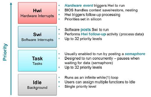
Figure 18. TI-RTOS Execution Threads
This section describes these four execution threads and various structures used throughout the TI-RTOS for messaging and synchronization. In most cases, the underlying TI-RTOS functions have been abstracted to higher-level functions in util.c (Util). The lower-level TI-RTOS functions are described in the TI-RTOS Kernel API Guide found here TI-RTOS Kernel User Guide. This document also defines the packages and modules included with the TI-RTOS.
Hardware Interrupts (Hwi)
Hwi threads (also called Interrupt Service Routines or ISRs) are the threads with the highest priority in a TI-RTOS application. Hwi threads are used to perform time critical tasks that are subject to hard deadlines. They are triggered in response to external asynchronous events (interrupts) that occur in the real-time environment. Hwi threads always run to completion but can be preempted temporarily by Hwi threads triggered by other interrupts, if enabled. Specific information on the nesting, vectoring, and functionality of interrupts can be found in the CC26xx Technical Reference Manual.
Generally, interrupt service routines are kept short as not to affect the hard real-time system requirements. Also, as Hwis must run to completion, no blocking APIs may be called from within this context.
TI-RTOS drivers that require interrupts will initialize the required interrupts for the assigned peripheral. See Drivers for more information.
Note
Debugging provides an example of using GPIOs and Hwis. While the SDK includes a peripheral driver library to abstract hardware register access, it is suggested to use the thread-safe TI-RTOS drivers as described in Drivers.
The Hwi module for the CC2640R2F also supports Zero-latency interrupts. These interrupts do not go through the TI-RTOS Hwi dispatcher and therefore are more responsive than standard interrupts, however this feature prohibits its interrupt service routine from invoking any TI-RTOS kernel APIs directly. It is up to the ISR to preserve its own context to prevent it from interfering with the kernel’s scheduler.
For the Bluetooth low energy protocol stack to meet RF time-critical requirements, all application-defined Hwis execute at the lowest priority. TI does not recommend modifying the default Hwi priority when adding new Hwis to the system. No application-defined critical sections should exist to prevent breaking TI-RTOS or time-critical sections of the Bluetooth low energy protocol stack. Code executing in a critical section prevents processing of real-time interrupt-related events.
Software Interrupts (Swi)
Patterned after hardware interrupts (Hwi), software interrupt threads provide additional priority levels between Hwi threads and Task threads. Unlike Hwis, which are triggered by hardware interrupts, Swis are triggered programmatically by calling certain Swi module APIs. Swis handle threads subject to time constraints that preclude them from being run as tasks, but whose deadlines are not as severe as those of hardware ISRs. Like Hwis’, Swis’ threads always run to completion. Swis allow Hwis to defer less critical processing to a lower-priority thread, minimizing the time the CPU spends inside an interrupt service routine, where other Hwis can be disabled. Swis require only enough space to save the context for each Swi interrupt priority level, while Tasks use a separate stack for each thread.
Similar with Hwis, Swis should be kept to short and may not include any blocking
API calls. This allows high priority tasks such as the wireless protocol
stack to execute as needed. It is suggested to _post() some TI-RTOS
synchronization primitive to allow for further post processing from within a
Task context. See Figure 19. to illustrate such a
use-case.
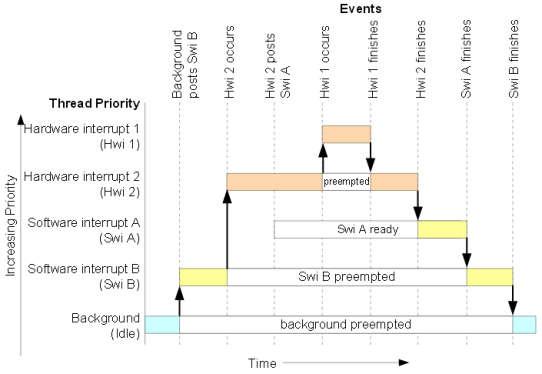
Figure 19. Preemption Scenario
The commonly used Clock module operates from within a Swi context. It is important that functions called by a Clock object do not invoke blocking APIs and are rather short in execution.
Task
Task threads have higher priority than the background (Idle) thread and lower priority than software interrupts. Tasks differ from software interrupts in that they can wait (block) during execution until necessary resources are available. Tasks require a separate stack for each thread. TI-RTOS provides a number of mechanisms that can be used for inter-task communication and synchronization. These include Semaphores, Event, Message queues, and Mailboxes.
See Tasks for more details.
Idle Task
Idle threads execute at the lowest priority in a TI-RTOS application and are executed one after another in a continuous loop (the Idle Loop). After main returns, a TI-RTOS application calls the startup routine for each TI-RTOS module and then falls into the Idle Loop. Each thread must wait for all others to finish executing before it is called again. The Idle Loop runs continuously except when it is preempted by higher-priority threads. Only functions that do not have hard deadlines should be executed in the Idle Loop.
For CC2640R2F devices, the idle task allows the Power Policy Manager to enter the lowest allowable power savings.
Kernel Configuration
A TI-RTOS application configures the TI-RTOS kernel using a configuration
(.cfg file) that is found within the project. In IAR and CCS
projects, this file is found in the application project workspace under the
TOOLS folder.
The configuration is accomplished by selectively including or using
term:RTSC modules available to the kernel. To use a module, the .cfg
calls xdc.useModule() after which it can set various options as defined
in the TI-RTOS Kernel User Guide.
Note
Projects in the BLE-Stack (such as simple_peripheral) typically will
contain a app_ble.cfg configuration file.
Some of the option that can be configured in the .cfg file include but are
not limited to:
- Boot options
- Number of Hwi, Swi, and Task priorities
- Exception and Error handling
- The duration of a System tick (the most fundamental unit of time in the TI-RTOS kernel).
- Defining the application’s entry point and interrupt vector
- TI-RTOS heaps and stacks (not to be confused with other heap managers!)
- Including pre-compiled kernel and TI-RTOS driver libraries
- System provides (for
System_printf())
Whenever a change in the .cfg file is made, you will rerun the XDCTools’
configuro tool. This step is already handled for you as a pre-build step in
the provided IAR and CCS examples.
Note
The name of the .cfg doesn’t really matter. A project should however only
include one .cfg file.
For CC26xx and CC13xx devices, a TI-RTOS kernel exists in ROM.
Typically for flash footprint savings, the .cfg will include the kernel’s
ROM module as shown in Listing 3.
/* ================ ROM configuration ================ */
/*
 * To use BIOS in flash, comment out the code block below.
 */
if (typeof NO_ROM == 'undefined' || (typeof NO_ROM != 'undefined' && NO_ROM == 0))
{
  var ROM = xdc.useModule('ti.sysbios.rom.ROM');
  if (Program.cpu.deviceName.match(/CC26/)) {
      ROM.romName = ROM.CC2640R2F;
  }
  else if (Program.cpu.deviceName.match(/CC13/)) {
      ROM.romName = ROM.CC1350;
  }
}
The TI-RTOS kernel in ROM is optimized for performance. If additional instrumentation is required in your application (tpyically for debugging), you must include the TI-RTOS kernel in flash which will increase flash memory consumption. Shown below is a short list of requirements to use the TI-RTOS kernel in ROM.
BIOS.assertsEnabledmust be set tofalseBIOS.logsEnabledmust be set tofalseBIOS.taskEnabledmust be set totrueBIOS.swiEnabledmust be set totrueBIOS.runtimeCreatesEnabledmust be set totrue- BIOS must use the
ti.sysbios.gates.GateMutexmoduleClock.tickSourcemust be set toClock.TickSource_TIMERSemaphore.supportsPrioritymust befalse- Swi, Task, and Hwi hooks are not permitted
- Swi, Task, and Hwi name instances are not permitted
- Task stack checking is disabled
Hwi.disablePrioritymust be set to0x20Hwi.dispatcherAutoNestingSupportmust be set to true- The default Heap instance must set to the
ti.sysbios.heaps.HeapMemmanager
For additional documentation in regards to the list described above, see the TI-RTOS Kernel User Guide.
Creating vs. Constructing
Most TI-RTOS modules commonly have _create() and _construct() APIs to
initialize primitive instances. The main runtime differences between the two
APIs is memory allocation and error handling.
Create APIs perform a memory allocation from the default TI-RTOS heap before initialization. As a result, the application must check the return value for a valid handle before continuing.
1 2 3 4 5 6 7 8 9 10 | Semaphore_Handle sem;
Semaphore_Params semParams;
Semaphore_Params_init(&semParams);
sem = Semaphore_create(0, &semParams, NULL); /* Memory allocated in here */
if (sem == NULL) /* Check if the handle is valid */
{
System_abort("Semaphore could not be created");
}
|
Construct APIs are given a data structure with which to store the instance’s variables. As the memory has been pre-allocated for the instance, error checking may not be required after constructing.
1 2 3 4 5 6 7 8 9 | Semaphore_Handle sem;
Semaphore_Params semParams;
Semaphore_Struct structSem; /* Memory allocated at build time */
Semaphore_Params_init(&semParams);
Semaphore_construct(&structSem, 0, &semParams);
/* It's optional to store the handle */
sem = Semaphore_handle(&structSem);
|
Thread Synchronization
The TI-RTOS kernel provides several modules for synchronizing tasks such as Semaphore, Event, and Queue. The following sections discuss these common TI-RTOS primitives.
Semaphores
Semaphores are commonly used for task synchronization and mutual exclusions
throughout TI-RTOS applications. Figure 20. shows the semaphore
functionality. Semaphores can be counting semaphores or binary semaphores.
Counting semaphores keep track of the number of times the semaphore is posted
with Semaphore_post(). When a group of resources are shared between tasks,
this function is useful. Such tasks might call Semaphore_pend() to see if a
resource is available before using one. Binary semaphores can have only two
states: available (count = 1) and unavailable (count = 0). Binary semaphores
can be used to share a single resource between tasks or for a basic-signaling
mechanism where the semaphore can be posted multiple times. Binary semaphores do
not keep track of the count; they track only whether the semaphore has been
posted.
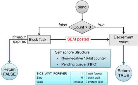
Figure 20. Semaphore Functionality
Initializing a Semaphore
The following code depicts how a semaphore is initialized in TI-RTOS. Semaphores can be created and contructed as explained in Creating vs. Constructing.
See Listing 4. on how to create a Semaphore.
See Listing 5. on how to construct a Semaphore.
Pending on a Semaphore
Semaphore_pend() is a blocking function call. This call may only be called
from within a Task context. A task calling this function will allow lower
priority tasks to execute, if they are ready to run. A task calling
Semaphore_pend() will block if its counter is 0, otherwise it will decrement
the counter by one. The task will remain blocked until another thread calls
Semaphore_post() or if the supplied system tick timeout has occurred;
whichever comes first. By reading the return value of Semaphore_pend() it is
possible to distinguish if a semaphore was posted or if it timed out.
1 2 3 4 5 6 7 8 9 10 11 12 13 14 | bool isSuccessful;
uint32_t timeout = 1000 * (1000/Clock_tickPeriod);
/* Pend (approximately) up to 1 second */
isSuccessful = Semaphore_pend(sem, timeoutInTicks);
if (isSuccessful)
{
System_printf("Semaphore was posted");
}
else
{
System_printf("Semaphore timed out");
}
|
Note
The default TI-RTOS system tick period is 1 millisecond. This default is
reconfigured to 10 microseconds for CC26xx and CC13xx devices by setting
Clock.tickPeriod = 10 in the .cfg file.
Given a system tick of 10 microseconds, timeout in
Listing 6. will be approximately 1 second.
Posting a Semaphore
Posting a semaphore is accomplished via a call to Semaphore_post(). A task
that is pending on a posted semaphore will transition from a blocked state to
a ready state. If no higher priority thread is ready to run, it will allow
the previously pending task to execute. If no task is pending on the semaphore,
a call to Semaphore_post() will increment its counter. Binary semaphores
have a maximum count of 1.
1 | Semaphore_post(sem);
|
Event
Semaphores themselves provide rudimentry synchronization between threads. There are cases just the Semaphore itself is enough to understand on what process needs to be triggered. Often however, a specific causes for the synchronization need to be passed across threads as well. To help accomplish this, one can utilize the TI-RTOS Event module. Events are similar to Semaphores in a sense that each instance of an event object acutally contains a Semaphore. The added advantage of using Events lie in the fact that tasks can be notified of specific events in a thread-safe manner.
Initializing an Event
Creating and constructing events follow the same guidlines as explained in Creating vs. Constructing. Shown in Listing 8. is an example on how to construct an Event instance.
1 2 3 4 5 6 7 8 9 | Event_Handle event;
Event_Params eventParams;
Event_Struct structEvent; /* Memory allocated at build time */
Event_Params_init(&eventParams);
Event_construct(&structEvent, 0, &eventParams);
/* It's optional to store the handle */
event = Event_handle(&structEvent);
|
Pending on an Event
Similar to Semaphore_pend(), a task thread would typically block on an
Event_pend() until an event is posted via an Event_post() or if the
specified timeout expired. Shown in Listing 9. is a snippet
of a task pending on any of the 3 sample event IDs shown below.
BIOS_WAIT_FOREVER is used to prevent a timeout from occuring. As a result,
Event_pend() will have one or more events posted in the returned bitmasked
value.
Each event returned from Event_pend() has been automatically cleared within
the event instance in a thread-safe manner. Therefore, its only neccessary to
keep a local copy of posted events. For full details on how to use
Event_pend(), see the TI-RTOS Kernel User Guide.
1 2 3 4 5 6 7 8 9 10 11 12 13 14 15 16 17 18 19 20 21 22 23 24 25 26 27 28 29 30 31 32 33 34 35 | #define START_ADVERTISING_EVT Event_Id_00
#define START_CONN_UPDATE_EVT Event_Id_01
#define CONN_PARAM_TIMEOUT_EVT Event_Id_02
void TaskFxn(..)
{
/* Local copy of events that have been posted */
uint32_t events;
while(1)
{
/* Wait for an event to be posted */
events = Event_pend(event,
Event_Id_NONE,
START_ADVERTISING_EVT |
START_CONN_UPDATE_EVT |
CONN_PARAM_TIMEOUT_EVT,
BIOS_WAIT_FOREVER);
if (events & START_ADVERTISING_EVT)
{
/* Process this event */
}
if (events & START_CONN_UPDATE_EVT)
{
/* Process this event */
}
if (events & CONN_PARAM_TIMEOUT_EVT)
{
/* Process this event */
}
}
}
|
Note
The default TI-RTOS system tick period is 1 millisecond. This default is
reconfigured to 10 microseconds for CC26xx and CC13xx devices by setting
Clock.tickPeriod = 10 in the .cfg file.
Given a system tick of 10 microseconds, timeout in
Listing 6. will be approximately 1 second.
Posting an Event
Events may be posted from any TI-RTOS kernel contexts and is simply done by
calling Event_post() of the event instance and the event ID.
Listing 10. shows how a high priorty thread such as a Swi
could post a specific event.
1 2 3 4 5 6 7 8 | #define START_ADVERTISING_EVT Event_Id_00
#define START_CONN_UPDATE_EVT Event_Id_01
#define CONN_PARAM_TIMEOUT_EVT Event_Id_02
void SwiFxn(UArg arg)
{
Event_post(event, START_ADVERTISING_EVT);
}
|
Queues
Queues let applications process messages in a first in, first out (FIFO) order. A project may use a queue to manage internal events coming from application profiles or another task. Clocks must be used when an event must be processed in a time-critical manner. Queues are more useful for message passing across various thread contexts.
The Queue module provides a unidirectional method of message passing between threads using a FIFO. In Figure 21. a queue is configured for unidirectional communication from task A to task B. Task A pushes messages into the queue and task B pops messages from the queue in order. Figure 21. shows the queue messaging process.
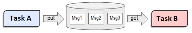
Figure 21. Queue Messaging Process
The TI-RTOS Queue functions have been abstracted into functions in the util.c
file. See the Queue module in the TI-RTOS Kernel User Guide for the
underlying functions. These utility functions combine the Queue module with the
ability to notify the recipient task of an available message through TI-RTOS Event
Module.
In CC2640R2F software, the event used for this process is the same event that the
given task uses for task synchronization through ICall. For an example of this,
see the SimpleBLECentral_enqueueMsg() function. Queues are commonly used to
limit the processing time of application callbacks in the context of the higher
priority threads. In this manner, the higher priority thread queues a message to
the application later processing instead of immediate processing in its own
context.
The Util modules contains a set of abstracted TI-RTOS Queue functions as
shown here:
- Util_constructQueue() creates a queue.
- Util_enqueueMsg() puts items into the queue.
- Util_dequeueMsg() gets items from the queue.
Functional Example
Figure 22. and Figure 23. illustrate how a queue can be used to enqueue a button press from Hwi (to Swi in the Board Key module) to be processed within a Task when no other high priority events are occuring. The example was taken from the from the simple_central project in BLE-Stack 3.00.00.
![@startuml
hide footbox
box "Swi context"
participant "Board Key module" as A
participant simple_central.c as B
database appMsgQueue as C
end box
-[#red]> A : Key press interrupt
<[#red]-- A
activate A
autonumber
A -> B : SimpleBLECentral_keyChangeHandler();
activate B
note right: Add SBC_KEY_CHANGE_EVT into the queue
B -> B : SimpleBLECentral_enqueueMsg();
activate B
autonumber stop
B -> : ICall_malloc();
B -> C: Util_enqueueMsg();
activate C
C --> B:
deactivate C
B -> : Event_post();
deactivate B
B --> A
deactivate B
deactivate A
@enduml](../_images/plantuml-413f41898ef244f8b20d73f416857c3c54b99739.png)
Figure 22. Sequence diagram for enqueuing a message
With interrupts enabled, a pin interrupt can occur asynchronously within a
Hwi context. To keep interrupts as short as possible, the work
associated with the interrupt is deferred to lower priority contexts for
processing. In the simple_central example found in BLE-Stack 3.00.00, pin
interrupts are abstracted via a Board Key module. This module will notify
registered functions via a callback from within a Swi context. In this
case, SimpleBLECentral_keyChangeHandler is the registered callback function.
Step 1 in Figure 22. shows the callback to
SimpleBLECentral_keyChangeHandler when a key is pressed. This event is
placed into the application’s queue for processing.
1 2 3 4 | void SimpleBLECentral_keyChangeHandler(uint8 keys)
{
SimpleBLECentral_enqueueMsg(SBC_KEY_CHANGE_EVT, keys, NULL);
}
|
Step 2 in Figure 22. shows how this key press is enqueued
for simple_central. Here, memory is allocated from ICall_malloc() to be
added to the queue. Once added to the queue, Util_enqueueMsg() will
generate a UTIL_QUEUE_EVENT_ID for the application to process.
1 2 3 4 5 6 7 8 9 10 11 12 13 14 15 16 17 | static uint8_t SimpleBLECentral_enqueueMsg(uint8_t event, uint8_t state, uint8_t *pData)
{
sbcEvt_t *pMsg = ICall_malloc(sizeof(sbcEvt_t));
// Create dynamic pointer to message.
if (pMsg)
{
pMsg->hdr.event = event;
pMsg->hdr.state = state;
pMsg->pData = pData;
// Enqueue the message.
return Util_enqueueMsg(appMsgQueue, sem, (uint8_t *)pMsg);
}
return FALSE;
}
|
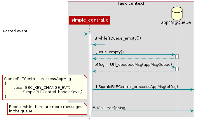
Figure 23. Sequence diagram for dequeuing a message
Step 3 in Figure 23., the simple_central application is
unblocked by the posted UTIL_QUEUE_EVENT_ID event where it proceeds to
check if any messages have been placed in the queue for processing.
1 2 3 4 5 6 7 8 9 10 11 12 13 | // If TI-RTOS queue is not empty, process app message
while (!Queue_empty(appMsgQueue))
{
sbcEvt_t *pMsg = (sbcEvt_t *)Util_dequeueMsg(appMsgQueue);
if (pMsg)
{
// Process message
SimpleBLECentral_processAppMsg(pMsg);
// Free the space from the message
ICall_free(pMsg);
}
}
|
Step 4 in Figure 23., the simple_central application takes the dequeue message and starts processing it.
1 2 3 4 5 6 7 8 | static void SimpleBLECentral_processAppMsg(sbcEvt_t *pMsg)
{
switch (pMsg->hdr.event)
{
case SBC_KEY_CHANGE_EVT:
SimpleBLECentral_handleKeys(0, pMsg->hdr.state);
break;
...
|
Step 5 in Figure 23., the simple_central application can now free the memory.
Note
The Bluetooth low energy stack abstacts the Queue modules via the Util module.
Tasks
TI-RTOS Tasks are equivalent to independent threads that conceptually execute functions in parallel within a single C program. In reality, switching the processor from one task to another helps achieve concurrency. Each task is always in one of the following modes of execution:
- Running: task is currently running
- Ready: task is scheduled for execution
- Blocked: task is suspended from execution
- Terminated: task is terminated from execution
- Inactive: task is on inactive list
One (and only one) task is always running, even if it is only the idle task (see Figure 18.). The current running task can be blocked from execution by calling certain task module functions, as well as functions provided by other modules like Semaphores. The current task can also terminate itself. In either case, the processor is switched to the highest priority task that is ready to run. See the Task module in the package ti.sysbios.knl section of the TI-RTOS Kernel User Guide for more information on these functions.
Numeric priorities are assigned to tasks, and multiple tasks can have the same priority. Tasks are readied to execute by highest to lowest priority level; tasks of the same priority are scheduled in order of arrival. The priority of the currently running task is never lower than the priority of any ready task. The running task is preempted and rescheduled to execute when there is a ready task of higher priority.
In the simple_peripheral application, the Bluetooth low energy protocol stack task is given the highest priority (5) and the application task is given the lowest priority (1).
Initializing a Task
When a task is initialized, it has its own runtime stack for storing local variables as well as further nesting of function calls. All tasks executing within a single program share a common set of global variables, accessed according to the standard rules of scope for C functions. This set of memory is the context of the task. The following is an example of the application task being constructed.
1 2 3 4 5 6 7 8 9 10 11 12 13 14 15 16 17 18 19 20 21 22 23 24 25 26 27 28 29 30 31 32 33 34 35 36 37 38 39 40 41 42 43 44 | #include <xdc/std.h>
#include <ti/sysbios/BIOS.h>
#include <ti/sysbios/knl/Task.h>
/* Task's stack */
uint8_t sbcTaskStack[TASK_STACK_SIZE];
/* Task object (to be constructed) */
Task_Struct task0;
/* Task function */
void taskFunction(UArg arg0, UArg arg1)
{
/* Local variables. Variables here go onto task stack!! */
/* Run one-time code when task starts */
while (1) /* Run loop forever (unless terminated) */
{
/*
* Block on a signal or for a duration. Examples:
* ``Sempahore_pend()``
* ``Event_pend()``
* ``Task_sleep()``
*
* "Process data"
*/
}
}
int main() {
Task_Params taskParams;
// Configure task
Task_Params_init(&taskParams);
taskParams.stack = sbcTaskStack;
taskParams.stackSize = TASK_STACK_SIZE;
taskParams.priority = TASK_PRIORITY;
Task_construct(&task0, taskFunction, &taskParams, NULL);
BIOS_start();
}
|
The task creation is done in the main() function, before the TI-RTOS Kernel’s
scheduler is started by BIOS_start(). The task executes at its assigned
priority level after the scheduler is started.
TI recommends using an existing application task for application-specific
processing. When adding an additional task to the application project, the
priority of the task must be assigned a priority within the TI-RTOS
priority-level range, defined in the TI-RTOS configuration file (.cfg).
Tip
Reduce the number of Task priority levels to gain additional RAM savings in
the TI-RTOS configuration file (.cfg):
Task.numPriorities = 6;
Do not add a task with a priority equal to or higher than the Bluetooth low energy protocol stack task and related supporting tasks (for example, the GapRole task). See Standard Project Task Hierarchy for details on the system task hierarchy.
Ensure the task has a minimum task stack size of 512 bytes of predefined memory. At a minimum, each stack must be large enough to handle normal subroutine calls and one task preemption context. A task preemption context is the context that is saved when one task preempts another as a result of an interrupt thread readying a higher priority task. Using the TI-RTOS profiling tools of the IDE, the task can be analyzed to determine the peak task stack usage.
Note
The term created describes the instantiation of a task. The actual TI-RTOS method is to construct the task. See Creating vs. Constructing for details on constructing TI-RTOS objects.
A Task Function
When a task is initialized, a function pointer to a task function is passed to
the Task_construct function. When the task first gets a chance to process,
this is the function which the TI-RTOS runs. Listing 15.
shows the general topology of this task function.
In typical use cases, the task spends most of its time in the blocked state,
where it calls a _pend() API such as Semaphore_pend(). Often,
high priority threads such as Hwis or Swis unblock the task with a _post()
API such as Semaphore_post().
Clocks
Clock instances are functions that can be scheduled to run after a certain
number of system ticks. Clock instances are either one-shot or periodic. These
instances start immediately upon creation, are configured to start after a
delay, and can be stopped at any time. All clock instances are executed when
they expire in the context of a Swi. The following example shows the
minimum resolution is the TI-RTOS clock tick period set in the TI-RTOS
configuration file (.cfg).
Note
The default TI-RTOS kernel tick period is 1 millisecond. For CC2640R2F
devices, this is reconfigured in the TI-RTOS configuration file (.cfg):
Clock.tickPeriod = 10;
Each system tick, which is derived from the real-time clock RTC, launches a Clock object that compares the running tick count with the period of each clock to determine if the associated function should run. For higher-resolution timers, TI recommends using a 16-bit hardware timer channel or the sensor controller. See the Clock module in the package ti.sysbios.knl section of the TI-RTOS Kernel User Guide for more information on these functions.
You can use the Kernel’s Clock APIs directly in your application and in addition
the Util module also contains a set of abstracted TI-RTOS Clock functions as
shown here:
- Util_constructClock() creates a clock object.
- Util_startClock() starts an existing clock object.
- Util_restartClock() stops, restarts an existing clock object.
- Util_isActive() checks if a clock object is running.
- Util_stopClock() stop an existing clock object.
- Util_rescheduleClock() reconfigure an existing clock object.
Functional Example
The following example was taken from the simple_peripheral project in BLE-Stack 3.00.00.
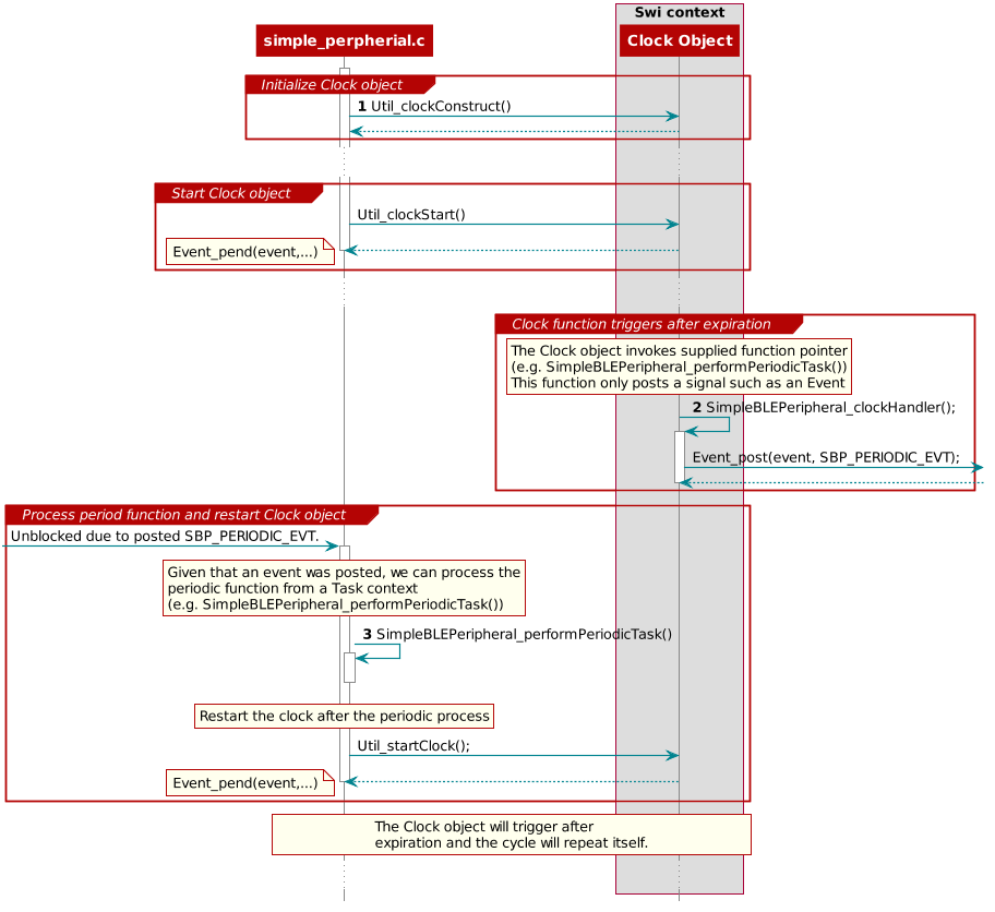
Figure 24. Triggering clock objects
Step 1 in Triggering clock objects constructs the Clock object via Util_constructClock(). After the example entered a connected state, it will then start the clock object via a Util_startClock().
// Clock instances for internal periodic events.
static Clock_Struct periodicClock;

// Create one-shot clocks for internal periodic events.
Util_constructClock(&periodicClock, SimpleBLEPeripheral_clockHandler,
    SBP_PERIODIC_EVT_PERIOD, 0, false, SBP_PERIODIC_EVT);
Step 2 in Triggering clock objects, after the Clock object’s timer expired,
it will execute SimpleBLEPeripheral_clockHandler() within a Swi context. As
this call cannot be blocked and blocks all Tasks, it is kept short by invoking
an Event_post(SBP_PERIODIC_EVT) for post processing in simple_peripheral.
static void SimpleBLEPeripheral_clockHandler(UArg arg)
{
    /* arg is passed in from Clock_construct() */
    Event_post(events, arg);
}
Attention
Clock functions must not call blocking kernel APIs or TI-RTOS driver APIs! Executing long routines will impact real-time constraints placed in high priority tasks allocated for wireless protocol stacks!
Step 3 in Triggering clock objects, the simple_peripheral task is
unblocked due the Event_post(SBP_PERIODIC_EVT), where it proceeds to invoke
the SimpleBLEPeripheral_performPeriodicTask() function. Afterwards, to
restart the periodic execution of this function, it will restart the
periodicClock Clock object.
if (events & SBP_PERIODIC_EVT)
{
  // Perform periodic application task
  SimpleBLEPeripheral_performPeriodicTask();

  Util_startClock(&periodicClock);
}
Drivers
The TI-RTOS provides a suite of CC26xx peripheral drivers that can be added to an application. The drivers provide a mechanism for the application to interface with the CC26xx onboard peripherals and communicate with external devices. These drivers make use of DriverLib to abstract register access.
There is significant documentation relating to each TI-RTOS driver located in the BLE-Stack. Refer to the BLE-Stack release notes for the specific location. This section only provides an overview of how drivers fit into the software ecosystem. For a description of available features and driver APIs, refer to the TI-RTOS API Reference.
Adding a Driver
Some of the drivers are added to the project as source files in their respective folder under the Drivers folder in the project workspace, as shown in Figure 25.
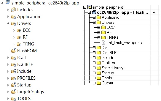
Figure 25. Drivers Folder
The driver source files can be found in their respective folder at $TI_RTOS_DRIVERS_BASE$\ti\drivers.
The $TI_RTOS_DRIVERS_BASE$ argument variable refers to the installation location and can be viewed in IAR Tools\ Configure Custom Argument Variables menu. For CCS, the corresponding path variables are defined in the Project Options\ Resource\Linked Resources, Path Variables tab.
The ECC and TRNG drivers, for example, are part of the BLE-Stack, not the TIRTOS, and they are located at <SDK_INSTALL_DIR>\examples\rtos\CC2640R2_LAUNCHXL\blestack\common\cc26xx\ecc and <SDK_INSTALL_DIR>\source\ti\blestack\hal\src\target\_common respectively.
To add a driver to a project, include the C and include file of the respective driver in the application file (or files) where the driver APIs are referenced.
For example, to add the PIN driver for reading or controlling an output I/O pin, add the following:
#include <ti/drivers/pin/PINCC26XX.h>
Also add the following TI-RTOS driver files to the project under the Drivers\PIN folder:
- PINCC26XX.c
- PINCC26XX.h
- PIN.h
This is described in more detail in the following sections.
Board File
The board file sets the parameters of the fixed driver configuration for a specific board configuration, such as configuring the GPIO table for the PIN driver or defining which pins are allocated to the I2C, SPI, or UART driver.
The board files for the CC2640R2 Launchpad are in the following path: <SDK_INSTALL_DIR>\examples\rtos\CC2640R2_LAUNCHXL\blestack\target\<Board_Type>
<Board_Type> is the actual device. To view the actual path to the board files, see the following:
- IAR: Tools→ Configure Custom Argument Variables
- CCS: Project Options→ Resources→ Linked Resources, Path Variables tab
In the path above, the <Board_Type> is selected based on a preprocessor symbol in the application project.
The top-level board file (board.c) then uses this symbol to include the correct board file into the project. This top-level board file can be found at <SDK_INSTALL_DIR>\examples\rtos\CC2640R2_LAUNCHXL\blestack\target\board.c, and is located under the Startup folder in the project workspace:
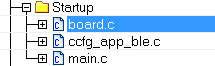
The board file links in another gateway board file located at <SDK_INSTALL_DIR>\examples\rtos\CC2640R2_LAUNCHXL\blestack\target\<board_type>, which finally links in the actual board file from <SDK_INSTALL_DIR>\source\ti\boards\<board_type>.
Board Level Drivers
There are also several board driver files which are a layer of abstraction on top of TI-RTOS drivers, to function for a specific board, for example Board_key.c. If desired, these files can be adapted to work for a custom board.
Creating a Custom Board File
A custom board file must be created to design a project for a custom hardware board. TI recommends starting with an existing board file and modifying it as needed. The easiest way to add a custom board file to a project is to replace the top-level board file. If flexibility is desired to switch back to an included board file, the linking scheme defined in Adding a Driver should be used.
At minimum, the board file must contain a PIN_Config structure that places all configured and unused pins in a default, safe state and defines the state when the pin is used. This structure is used to initialize the pins in main() as described in Pre-main initialization. The board schematic layout must match the pin table for the custom board file Improper pin configurations can lead to run-time exceptions:
PIN_init(BoardGpioInitTable);
See the PIN driver documentation for more information on configuring this table.
Available Drivers
This section describes each available driver and provide a basic example of adding the driver to the simple_peripheral project. For more detailed information on each driver, see the TI-RTOS API Reference.
PIN
The PIN driver allows control of the I/O pins for software-controlled general-purpose I/O (GPIO) or connections to hardware peripherals. As stated in the Board File section, the pins must first be initialized to a safe state (configured in the board file) in main(). After this initialization, any module can use the PIN driver to configure a set of pins for use. The following is an example of configuring the simple_peripheral task to use one pin as an interrupt and another as an output, to toggle when the interrupt occurs. IOID_x pin numbers map to DIO pin numbers as referenced in CC26xx Technical Reference Manual. The following table lists pins used and their mapping on the CC2640R2F LaunchPad. These are already defined in the board file.
| Signal Name | Pin ID | CC2640R2F LaunchPad Mapping |
|---|---|---|
| CC2640R2_LAUNCHXL_PIN_RLED | IOID_6 | DIO6 (Red) |
| CC2640R2_LAUNCHXL_PIN_BTN1 | IOID_13 | DIO13 (BTN_1) |
The following simple_peripheral.c code modifications are required.
Include PIN driver files:
#include <ti/drivers/pin/PINCC26xx.h>
Declare the pin configuration table and pin state and handle variables to be used by the simple_peripheral task:
static PIN_Config SBP_configTable[] =
{
    CC2640R2_LAUNCHXL_PIN_RLED | PIN_GPIO_OUTPUT_EN | PIN_GPIO_LOW | PIN_PUSHPULL | PIN_DRVSTR_MAX,
    CC2640R2_LAUNCHXL_PIN_BTN1 | PIN_INPUT_EN | PIN_PULLUP | PIN_IRQ_BOTHEDGES | PIN_HYSTERESIS,
    PIN_TERMINATE
};

static PIN_State sbpPins;
static PIN_Handle hSbpPins;
static uint8_t LED_value = 0;
Declare the ISR to be performed in the hwi context:
static void buttonHwiFxn(PIN_Handle hPin, PIN_Id pinId)
{
    SimpleBLEPeripheral_enqueueMsg(SBP_BTN_EVT, 0, NULL);
}
In SimpleBLEPeripheral_processAppMsg, add a case to handle the event from above, and define the event:
#define SBP_BTN_EVT

static void SimpleBLEPeripheral_processAppMsg(sbcEvt_t *pMsg)
{
    switch (pMsg->hdr.event)
    {
        case SBP_BTN_EVT:
            //toggle red LED
            if (LED_value)
            {
                PIN_setOutputValue(hSbpPins, CC2640R2_LAUNCHXL_PIN_RLED , LED_value--);
            }
            else
            {
                PIN_setOutputValue(hSbpPins, CC2640R2_LAUNCHXL_PIN_RLED, LED_value++);
            }
            break;
...
Open the pins for use and configure the interrupt in simple_peripheral_init():
// Open pin structure for use
hSbpPins = PIN_open(&sbpPins, SBP_configTable);
// Register ISR
PIN_registerIntCb(hSbpPins, buttonHwiFxn);
// Configure interrupt
PIN_setConfig(hSbpPins, PIN_BM_IRQ, CC2640R2_LAUNCHXL_PIN_BTN1 | PIN_IRQ_NEGEDGE);
// Enable wakeup
PIN_setConfig(hSbpPins, PINCC26XX_BM_WaKEUP, CC2640R2_LAUNCHXL_PIN_BTN1|PINCC26XX_WAKEUP_NEGEDGE);
Compile
Download
Run
Note
Pushing the BTN-1 button on the CC2640R2F LaunchPad toggles the red LED. No debouncing is implemented.
UART and SPI
There are many different methods of adding serial communication to a BLE project, and these are summarized in detail at the following wiki page.
Other Drivers
The other drivers included with TI-RTOS are: Crypto (AES), I2C, PDM, Power, RF, and UDMA. The stack makes use of the power, RF, and UDMA, so extra care must be taken if using these. As with the other drivers, these are well-documented, and examples are provided in the BLE-Stack.
Using 32-kHz Crystal-Less Mode
BLE-Stack 3.00.00 includes support for operating the CC2640R2F in a 32-kHz crystal-less mode for peripheral and broadcaster (beacon) configurations. By using the internal low-frequency RC oscillator (RCOSC_LF), the 32-kHz crystal can be removed from the board layout.
There are a few steps that must be taken to enable this feature. For any peripheral project, the following change is require for IAR. For CCS user, please see the Running Bluetooth Low Energy on CC2640 Without 32 kHz Crystal for the needed steps to enable RCOSC_LF in your project. You will find more detail regarding this feature in the aforementioned application note.
Include rcosc_calibration.c, rcosc_calibration.h and ccfg_app_ble_rcosc.c files which locate at <SDK_INSTALL_DIR>\examples\tos\CC2640R2_LAUNCHXL\ble\common\cc26xx\rcosc
Exclude ccfg_app_ble.c from build.
Add USE_RCOSC to Defined symbols.
Add the following code to your peripheralproject.c
#ifdef USE_RCOSC
#include "rcosc_calibration.h"
#endif //USE_RCOSC
Add the following code to your peripheralproject_init function in peripheralproject.c
#ifdef USE_RCOSC
RCOSC_enableCalibration();
#endif // USE_RCOSC
If using a custom board file, enable the RCOSC in the power policy. The board files included with the BLE-Stack:
PowerCC26XX_Config PowerCC26XX_config = {
  .policyInitFxn     = NULL,
  .policyFxn         = &PowerCC26XX_standbyPolicy,
  .calibrateFxn      = &PowerCC26XX_calibrate,
  .enablePolicy      = TRUE,
  .calibrateRCOSC_LF = TRUE,
  .calibrateRCOSC_HF = TRUE,
};
Constrain the temperature variation to be less than 1°C/sec. If the temperature is to change faster than 1°C/sec, then a short calibration interval must be used. Calibration interval can be tuned in rcosc_calibration.h
// 1000 ms
#define RCOSC_CALIBRATION_PERIOD   1000
Note
Use of the internal RCOSC_LF requires a sleep clock accuracy (SCA) of 500 ppm.
Power Management
All power-management functionality is handled by the peripheral drivers and the Bluetooth low energy protocol stack. This feature can be enabled or disabled by including or excluding the POWER_SAVING preprocessor-defined symbol. When POWER_SAVING is enabled, the device enters and exits sleep as required for Bluetooth low energy events, peripheral events, application timers, and so forth. When POWER_SAVING is undefined, the device stays awake. See Accessing Preprocessor Symbols in CCS or Accessing Preprocessor Symbols in IAR for steps to modify preprocessor-defined symbols.
More information on power-management functionality, including the API and a sample use case for a custom UART driver, can be found in the TI-RTOS Power Management for CC26xx included in the TI-RTOS install. These APIs are required only when using a custom driver.
Also see Measuring Bluetooth Smart Power Consumption (SWRA478) for steps to analyze the system power consumption and battery life.