Over the Air Download (OAD)
This section serves as a guide to the Texas Instruments Over the Air Download (OAD) ecosystem including the profile, application architecture, drivers, and middleware. OAD allows the firmware image running on a BLE device to be updated in the field without the need for wires or debuggers.
The guide will cover the princles of the OAD process, the out of the box demos included in the Simplelink CC2640R2 SDK, and the process for adding OAD to an existing project.
Scope
The OAD guide section will cover:
The supported development kit for OAD is the CC2640R2 Launchpad.
Warning
This guide assumes that both the OAD Target and the OAD Downloader are running on the CC2640R2 Launchpad. Two CC2640R2 Launchpad devices are required to follow this guide.
Read this Section First
Document Updates/Errata
This document is constantly being improved. For the best user experience, please ensure that you are using the latest version. Newer revisions will be posted online on the OAD User’s Guide wiki page.
OAD Concept Overview
This section aims to explain the major concepts involved in the OAD process from a high level. The concepts here will be expanded on further in the following sections. Some concepts, such as the Boot Image Manager (BIM) may vary in their implementation details. Wherever possible, the concepts will be covered in this chapter with their implementation details covered in the following chapters.
OAD Types
There are two methods of performing an over the air download: On-chip and Off-chip. The key difference between the two methods is where the downloaded image is to be stored during the OAD. In On-chip OAD, the downloaded image is written to internal flash, allowing for a single chip OAD solution. Off-Chip OAD stores the downloaded image in an external flash part, requiring a two chip OAD solution. Figure 69. shows a comparison of different OAD methods. Each type of OAD has associated tradeoffs and benefits which will be discussed in their respective sections. Despite their differences, both OAD methods share the same over the air profile and metadata vector described in this section
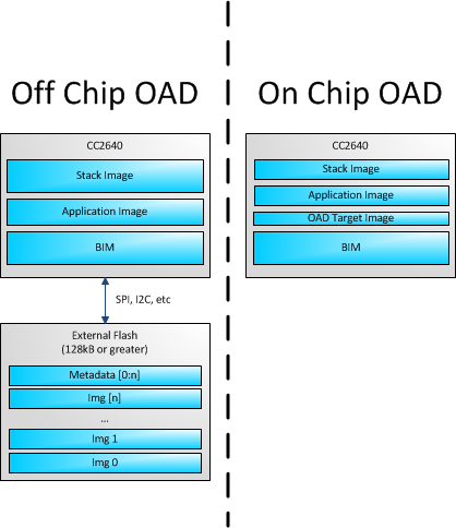
Figure 69. OAD Types Overview
OAD Topology Overview
Two BLE capable devices are required for performing an OAD. The terms for the devices involved in an OAD exchange are listed below:
OAD roles are independent of the GAP role; they are dependent on which device exposes the OAD service. The OAD Target is always the device that runs the OAD service (GATT server), and the OAD Downloader is always the device that consumes the OAD service (GATT client Figure 70. shows a graphical relationship of the devices required for an OAD transfer.
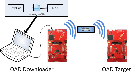
Figure 70. OAD Downloader and Target
All provided TI example applications (BTool, mobile applications, etc.) are implemented such that the OAD Target is a peripheral device, and the OAD Downloader is a central device. For this reason, other configurations are outside of the scope of this document.
OAD Image Metadata
There are many points in the OAD process where information must be gathered about images. This information can be used by the OAD service to determine whether or not an image is acceptable for download or by the bootloader to determine which image should be run. In order to prevent this information from being calculated multiple times and to assist in the linking process, all TI OAD images use a standard 16-byte metadata vector. This metadata vector is embedded at the beginning of the image, occupying the first 16 bytes before the application code. This section aims to explain the various fields within the metadata vector and what they mean. The following sections will describe how each field is used specifically for On-chip and Off-chip OAD.
Most metadata checking is done in OADTarget_validateNewImage().
Table 17. below shows a description of the metadata vector.
| Field | Size (in bytes) | Description |
|---|---|---|
| CRC | 2 | Cyclic Redundancy Check |
| CRC Shadow | 2 | Place holder for CRC |
| Version | 2 | Version |
| Length | 2 | Length of the image in words* |
| UID | 4 | User Identification |
| Start Address | 2 | The destination address of the image in words* |
| Image Type | 1 | The type of image to be downloaded |
| State | 1 | The status of this image |
Note
The above fields that are marked with an asterisk * are
measured in 32-bit words. For example, an image length of 0x100
describes an image that is 1024 bytes in size. This OAD word size is
defined by EFL_OAD_ADDR_RESOLUTION for off-chip OAD and by
HAL_FLASH_WORD_SIZE for on-chip OAD.
CRC and CRC Shadow
The cyclic redundancy check (CRC) is a means to check the integrity of an image. This must be done in two steps. First the CRC must be calculated when the image is generated from the toolchain, this will be stored in the CRC field within the metadata vector.
This initial CRC will be sent over the air via the OAD service (see OAD Service section). Later, the target will need to ensure that the image has not been corrupted during transfer. The target will then re-calculate the CRC of the downloaded image; this will be stored in the CRC shadow field of the metadata vector.
If the CRC and CRC shadow are equivalent, the target can assume that the image was not corrupted while sending over the air.
The algorithm selected for CRC calculations is the CRC-16-CCITT, it is a 16 bit CRC calculation that boasts a 99.9984% error detection rate in the worst case.
Version
The image version field is used to track revisions of images and ensure
upgrade compatibility. Customers may implement their own versioning
scheme; however, there are additional checks imposed by the TI OAD profile.
See the function OADTarget_validateNewImage() within
oad_target_external_flash.c or oad_target_internal_flash.c
how these version checks are done in Off-chip and On-chip OAD, respectively.
Length
The length field is the length of the image in words, where the word
size is defined by EFL_OAD_ADDR_RESOLUTION and HAL_FLASH_WORD_SIZE
for On-chip and Off-chip OAD respectively. Off-chip OAD customers who
are using different external flash parts may need to modify
EFL_OAD_ADDR_RESOLUTION to match the word size of their part. For
On-chip OAD, the word size of the CC2640R2F is fixed.
User Identification (UID)
This field is un-used by the TI OAD profile, but the hooks are in place for a customer to add their own implementation of verifying images based on UID.
For on-chip OAD, the convention is that Image A will embed ‘A’, ‘A’, ‘A’, ‘A’ and Image B will embed ‘B’, ‘B’, ‘B’, ‘B’. off-chip images use ‘E’, ‘E’, ‘E’, ‘E’ by default.
Start Address
The start address is the first address where the proposed image is to be stored in internal flash. Similar to the length field, this is calculated in words. Off-chip OAD solutions put restrictions on the start address based on image type (more on this in the next section).
Note
For On-chip OAD solutions, this field is reserved in the metadata as they use a fixed start address that is based on the internal flash memory map.
Image Type
In Off-chip OAD systems with external flash, there are multiple types of images that can be uploaded. These image types include:
- App + Stack
- App only
- Network Processor
- Stack only
Warning
While stack only upgrades are possible, the user must be sure that the App/Stack boundary has not changed between the resident OAD image and the proposed OAD image. Since there are no runtime checks on the App/Stack boundary, a Stack only OAD will overwrite the resident application if the boundary has grown. Users should exercise care when using this option.
If a boundary change is required (i.e. stack is growing or shrinking), it is required that a user perform a merged update (App+Stack) to ensure that the OAD image is ready to run.
Note
On-chip OAD solutions determine this image type based on the LSB of the image version field. The image type field is not used (reserved for future use).
The supported image types are listed below:
| Image Type | Value | Description |
|---|---|---|
| EFL_OAD_IMG_TYPE_APP | 1 | An application or application + stack merged update |
| EFL_OAD_IMG_TYPE_STACK | 2 | A stack only update |
| EFL_OAD_IMG_TYPE_NP | 3 |
|
| EFL_OAD_IMG_TYPE_FACTORY | 4 | Describes the permanently resident production image that runs on the device before any OTA updates. |
Image State
The image state is a one byte metadata field that is used only by Off-chip OAD solutions. The state informs the bootloader whether or not the image is ready to run or currently running. This prevents the bootloader from copying the same image from external to internal flash on every boot.
Note
For On-chip OAD solutions this field is reserved in the metadata as the OAD reset service handles switching between images in the bootloader.
OAD Service
The OAD service has been designed to provide a simple and customizable implementation for the customer. In its most rudimentary form, this service is responsible for accepting/rejecting an OAD interaction based on image header criteria, storing the image in its appropriate location, and causing a device reset if the download is successful so that the downloaded application image is run by the BIM.
A screenshot of BTool displaying the OAD service is shown below:
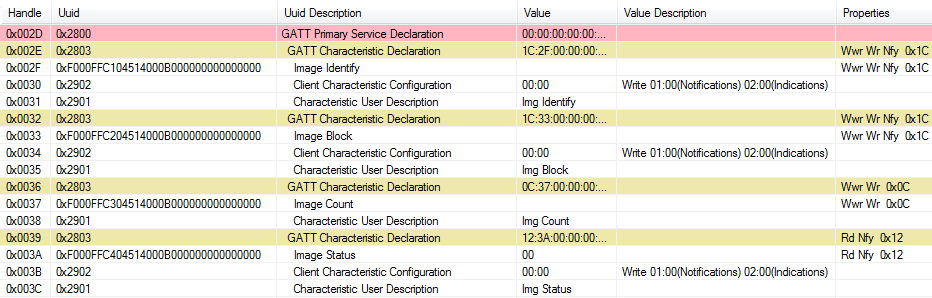
Figure 71. OAD Service Overview
The OAD service is a primary service with four characteristics. The characteristics of the OAD service, their UUIDs, and descriptions are listed in Figure 71.
Note
The characteristics use the 128-bit TI base UUID of the format F000XXXX-0451-4000-B000-000000000000 where XXXX is their shortened 16bit UUID. For brevity, this document will refer to the characteristics by their 16-bit short UUID.
| UUID | Name | Description |
|---|---|---|
| 0xFFC0 | OAD Service | OAD service declaration |
| 0xFFC1 | Image Identify | Used to send image metadata over the air so that the OAD Target device can determine if it should accept or reject the proposed image |
| 0xFFC2 | Image Block | Actual block of image data along with offset into the image. |
| 0xFFC3 | Image Count | Number of complete images to be downloaded in the OAD session |
| 0xFFC4 | Image Status | Status of current OAD download |
The primary method for sending data from the OAD Downloader to the OAD target is the GATT writes with no response message. GATT notifications are the primary method used to send data from the target to the downloader. This communication scheme was selected to prevent the target device from having to include the GATT client code required in order to receive notifications from the downloader. The OAD Downloader shall register for notifications from any characteristic with a CCCD (by writing 01:00 to the CCCD).
Note
Both GATT notifications and GATT write with no response are non-acknowledged message types. There is an inherent tradeoff between the speed of the OAD process and its reliability. Implementing a reliable OAD communication protocol (with retries, acknowledgments, etc.) is outside the scope of this document.
For a message sequence chart describing the OAD process in terms OAD service messages exchanged between the target and OAD Downloader please see Figure 76..
OAD Image Identify (0xFFC1)
The Image Identify characteristic is used to exchange image metadata between OAD Downloader and target. The OAD process begins when the OAD Downloader sends the 16 byte metadata of the proposed OAD image to the target. Upon receiving the candidate metadata, the target will do some calculations to determine whether or not the proposed image should be downloaded. “01:00” shall be written to the CCCD of this characteristic so that notification for metadata rejection is enabled.
Note
The conditions under which an OAD is accepted vary slightly
between the on and off-chip methods. Please see
OADTarget_validateNewImage() in oad_target_external_flash.c
for off-chip OAD and oad_target_internal_flash.c for on-chip OAD.
These functions implement the image reject conditions.
If the target accepts the image it will continue the OAD process by sending a notification on the Image Block characteristic requesting the first block. Otherwise the target will reject the image by sending back a portion the currently resident image’s metadata. The reject metadata contains the Image Version, Image version, and User ID fields. For more information about these fields, please refer to the metadata section.
A sniffer capture of the image identify characteristic being used to reject a candidate OAD image is shown below. Note that only image version, length, and user ID are contained in the reject notification.
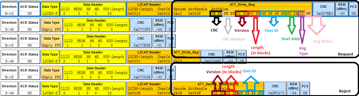
Figure 72. Reject Notification in Sniffer Capture
Alternatively, a successful OAD initiation is shown in below:
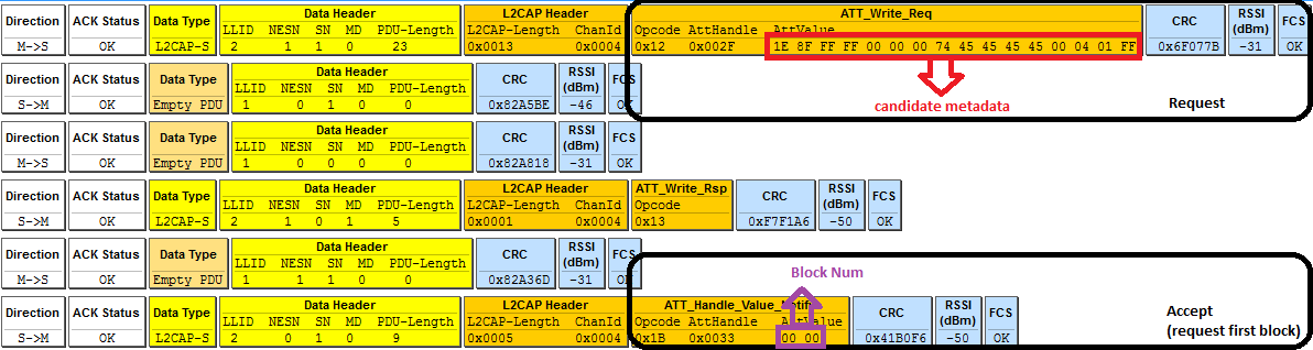
Figure 73. Successful OAD Initiation Sniffer Capture
OAD Image Block Characteristic (0xFFC2)
The OAD Image Block characteristic is used to request and transfer a block of the OAD image. “01:00” shall be written to the CCCD of this characteristic so that notification for block request is enabled. The target requests the next block of the image by sending a GATT notification to the OAD Downloader with the requested block number. The OAD Downloader will respond (GATT write no response) with the block number and a 16 byte OAD image block. The image block contains the actual binary data from OAD image offset by the block number. Figure 74. shows a block request/response sniffer capture.

Figure 74. Block Request/Response Sniffer Capture
In Figure 74. above, the block number field is 2 bytes (little endian) and highlighted in red. The OAD image block is 16 bytes and highlighted in purple.
OAD Image Count Characteristic (0xFFC3)
The OAD Image Count characteristic is used to set the number of OAD images to be downloaded. This is used for only Off-chip OAD and the default value of the characteristic is 1. Note On-chip OAD only supports one image download per session. See On-Chip OAD for details.
OAD Image Status (0xFFC4)
The OAD image status characteristic is used to report various failures that may occur during the OAD process. The OAD Downloader may use this information to determine why an OAD failed, so that it may correct for the errors and try again. “01:00” shall be written to the CCCD of this characteristic so that notification for status update is enabled. There are four OAD status messages that are defined by default. The OAD status codes are listed in the table below:
| OAD Status Code | Value | Description |
|---|---|---|
| OAD_SUCCESS | 0 | OAD succeeded |
| OAD_CRC_ERR | 1 | The downloaded image’s CRC doesn’t match the one expected from the metadata |
| OAD_FLASH_ERR | 2 | The external flash cannot be opened |
| OAD_BUFFER_OFL | 3 | The block number of the received packet doesn’t match the one requested. An overflow has occurred. |
The customer may extend these values as needed, and use the
OAD_sendStatus() function to send updates to the downloader.
OAD Reset Service
The OAD reset service is only used by on-chip OAD solutions. It implements a method for invalidating the currently running image and resetting the device. This must occur because in on-chip solutions the currently running image cannot update itself. More information about the on-chip OAD process will be covered in the on-chip OAD chapter. Figure 75. shows an overview of the OAD reset service and it’s characteristic. Like the OAD service, the reset service uses the 128 bit TI base UUID with a 16 bit short UUID of 0xFFD0.
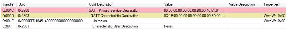
Figure 75. OAD Reset Service
OAD Reset (0xFFD1)
The OAD reset is accomplished by invalidating Image B, which forces the bootloader to revert to Image A until another successful OAD of Image B has occurred. Image B is invalidated by corrupting its CRC. After the corruption, the reset service immediately invokes a HAL reset to jump to the bootloader. Note that a GATT write of any value to the reset service will trigger a reset of the device/invalidation of Image B.
OAD Process
This Profile has been designed to provide a simple and customizable OAD Profile for the customer. In its most rudimentary form, for both On-chip and Off-chip OAD, this profile is responsible for accepting an OAD interaction based on image header criteria, storing the image onto the flash and causing a device reset if the download is successful so that the downloaded application image is run by the BIM. OAD Downloader and OAD Target perform Client role and Server role respectively.
Initiation of the On-chip OAD Process
After establishing a new connection, updating the connection interval for a faster OAD and enabling notifications of OAD Image Identify and OAD Image Block characteristics on the OAD Target, the OAD Downloader shall write to the Image Identify characteristic of the OAD Target. The message data will be the header retrieved from the OAD Image available for OAD.
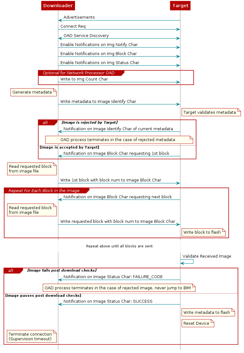
Figure 76. Sequence diagram for OAD process
Upon receiving the write request to the Image Identify characteristic, the OAD Target will compare the image available for OAD to its own running image. By default, only the image size and version number, which implies whether the image is of type A or B, are checked to determine if the new image is acceptable to download.
If the OAD Target determines that the image available for OAD is acceptable, the OAD Target will initiate the OAD process by notifying the Image Block Transfer characteristic to the OAD Downloader requesting the first block of the new image. Otherwise, if the OAD Target finds that the new image does not meet its criteria to begin the OAD process, it shall respond by notifying the Image Identify characteristic with its own Image Header data as sign of rejection. In that case, the OAD procedure will end at the moment where dotted ‘X’s are placed as depicted in Figure 76..
Image Block Transfers
The Image Block Transfer characteristic allows the two devices to
request and respond with the OAD image, one block at a time. The image
block size is defined to be 16 bytes – see OAD_BLOCK_SIZE in
oad.h. The OAD Target will request an image block from the
OAD Downloader by notifying the OAD Image Block characteristic with the
correct block index. The OAD Downloader shall then respond by writing to
the OAD Image Block characteristic. The message’s data will be the requested
block’s index followed by the corresponding 16-byte block of the image. Whenever
the OAD Target is ready to digest another block of the OAD image, it
will notify the Image Block Transfer characteristic with the index of
the desired image block. The OAD Downloader will then respond.
Completion of the On-chip OAD Process
After the OAD Target has received the final image block, it will verify that the image is correctly received and stored by calculating the CRC over the stored OAD image. The OAD Target will then invalidate its own image and reset so that the BIM can run the new image in-place. The burden is then on the Downloader, which will suffer a lost BLE connection to the OAD Target during this verification and instantiation process, to restart scanning and the to reestablish a connection and verify that the new image is indeed running.
Bootloader
Since a running image cannot update itself, both On-chip and Off-chip OAD methods must employ a bootloader. A bootloader is a lightweight section of code that is designed to run every time the device resets, check the validity of newly downloaded images, and if necessary, load the new image into internal flash. TI’s bootloader implementation is called the Boot Image Manager (BIM). BIM’s implementation varies slightly for On-chip and Off-chip OAD solutions, thus there is a separate BIM project for each.
bim_oad_onchipSee BIM for On-chip OADbim_oad_offchipSee BIM for Off-chip OAD
Off-Chip OAD
This section describes the offchip OAD process. Off-chip OAD utilizes an external memory component (Flash) to store the new image during download and bootloading. This section aims to address the following procedures that are unique to off-chip OAD:
For information about the OAD profile and metadata, please see OAD Concept Overview
Constraints and Requirements for Off-chip OAD
In order to perform off-chip OAD the target system must contain have:
- An external storage device such as Flash memory with at least 128kB of space
- Free GPIO pins to interface to the external memory (i.e. 4 wires for SPI)
- Enough free code space to reserve the entire contents of pg 31 (4kB) for BIM
- Ability to use the split image ICall architecture. See ICall for more information.
Off-chip OAD Memory layout
The memory maps for both internal and external flash are detailed below.
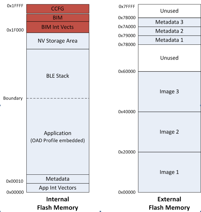
Figure 77. Off-Chip OAD Memory Layout
Off-chip OAD applications use both on-chip flash memory and off-chip flash memory device. The on-chip flash memory contains the Interrupt Vectors, the BLE Stack, the Application where OAD Profile is embedded, the BLE stack image, the NV Storage Area, the BIM and the CCFG.
The off-chip flash memory on the CC2640R2 Launchpad contains up to 3 OAD Images and up to 3
Metadatas corresponding to the OAD Images. The memory map layout of the external
flash part is defined in ext_flash_layout.h. The size of each OAD Image
placeholder is 128kB. The memory partition of the application for
Off-chip OAD is depicted in Figure 77..
Each OAD image, either App only or App+Stack, must support OAD Profile so that
further OAD is enabled after it is downloaded to the off-chip memory, copied to
the on-chip memory and executed.
The sectors in Figure 77. in red are designed to be permanently resident on the device. The BIM and CCFG are not intended to be upgraded via OAD. The OAD design was selected this way so that a failure during the OAD process does not yield a bricked device.
BIM for Off-chip OAD
Warning
The BIM will link the resident CCFG sector. Furthermore,
this is a custom CCFG, with the IMAGE_VALID_CONF field set to
0x1F000. This means that the boot ROM of the device will automatically
exectue BIM code instead of application code at startup. BIM
will handle starting the application. OAD applications will not need to
include a CCFG. This is a feature of CC2640R2F, and not compatible
with R1 devices.
The OAD solution requires that permanently resident boot code, the BIM, exists in order to provide a fail-safe mechanism for determining whether to run the existing application image or to copy a new image or images from off-chip flash to on-chip flash. It is assumed that a valid image exists either in off-chip flash ready to be copied or already placed in on-chip flash at any given time. Given this assumption, the initial image placed in internal flash which does not exist in external flash will have invalid external image metadata, and so the bootloader will choose to jump to the existing image’s entry point.
At startup, BIM checks if the application image metadata in off-chip flash has a status indicating that the image is to be copied to the on-chip flash. If the status is 0xFF, copies the image if a valid CRC and CRC Shadow are found. If the status is anything other than 0xFF, assumes the application in the on-chip flash is valid to run. If a 2 byte value is found that is neither 0x0000 nor 0xFFFF, but a 0xFFFF shadow checksum is found, the BIM computes the CRC over the image. Image length is determined by the metadata that is also stored contiguous with the CRC in on-chip flash that was copied over during the original write of the image from the off-chip flash.
If off-chip flash contains an image to be downloaded, but this
image is undesirable, BIM can be programmed with symbol NO_COPY
to skip image checking and jump directly into the image already placed in
on-chip flash; at which point the on-chip flash image could invalidate
the bad image’s metadata or OAD a new image in its place. BIM will not
be able to load any new images while NO_COPY is defined in the build.
BIM is only responsible for making an application image failsafe upon entry. BIM has exactly one entrance to the application image.
The BIM occupies the last flash page with CCFG and uses the interrupt vectors at the start of flash where the Reset Interrupt Vector calls the BIM startup routine to ensure its control of the system upon a device reset.
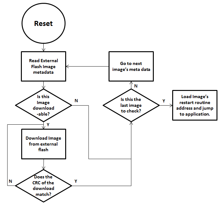
Figure 78. Functional Overview of Off-chip BIM
Out of the Box Demo (Off-Chip OAD)
The Simplelink CC2640R2 SDK includes demo projects that are setup to use OAD in advance. These build configurations may be flashed onto the device out of the box. All out of the box demos use BTool as the OAD Downloader. Please see OAD Topology Overview for more information. Ensure that BTool is setup correctly first. See BTool Setup for steps on how to do so. The steps listed below assume that a CC2640R2 Launchpad is being used. Additional steps may be required for custom hardware.
Furthermore, the steps in this section are referring to the OAD Target device, the images refrenced below should be flashed onto that device.
Using CCS
Warning
If both the OAD Target and the OAD Downloader are connected at the same time, CCS may load the image to the wrong device. This is because CCS will select the first XDS110 it finds. This behavior can be avoided by unplugging the OAD Target device, or by setting a multi emulator debug session using CCS. See the wiki Debug with Multiple Emulators for more information.
The steps below will describe how to run the out of the box demo for OAD on CCS.
Import the bim_oad_offchip, stack, and app projects into the workspace.
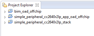
Figure 79. Offchip OAD CCS Workspace
Build and load the BIM project onto the CC2640R2 Launchpad
Build and load the
simple_peripheral_cc2640r2lp_stackproject onto the CC2640R2 LaunchpadBuild the and load the
simple_peripheral_cc2640r2lp_app_oad_offchipproject- Note that a special post build step will run and generate a new app image
file called
simple_peripheral_cc2640r2lp_app_oad.bin. This is the file to be provided to BTool and sent over the air.
- Note that a special post build step will run and generate a new app image
file called
You should now be able to observe that the device is advertising using BTool.
- See BTool OAD Verify Advertising for steps.
Make your application level changes that are intended for OAD update. Follow steps in Changing Application Data to Verify an OAD for a trivial way to change app to verify the OAD. Build the application with changes.
Use BTool to OAD your modified application file following the steps detailed in BTool OAD Procedure
- Make sure you are using the *_oad.bin file with BTool as this file contains the metadata.
Attention
After a successful OAD, you may need to re-start your CC2640R2F in order for it to advertise again. This is because the XDS110 driver may be still attached from previous debug sessions.
Using IAR
The steps below will describe how to run the out of the box demo for OAD on IAR.
Open the
bim_oad_offchipproject, build and load it onto the CC2640R2 Launchpad using the debugger.Open the
simple_peripheralworkspace.- Build and load the stack project.
- Be sure to use the
FlashROMbuild configuration for the stack. This configuration corresponds to the ICall split image architecture required by OAD.
Build and load the
simple_peripheralapplication project using theFlashROM_OAD_Offchipbuild config.You should now be able to observe that the device is advertising via BTool.
- See BTool OAD Verify Advertising for steps.
Make your application level changes that are intended for OAD update. Follow steps in Changing Application Data to Verify an OAD for a trivial way to change app to verify the OAD. Build the application with changes.
Use BTool to OAD your modified application file following the steps detailed in BTool OAD Procedure
- Make sure you are using the *_oad.bin file with BTool as this file
contains the metadata. By default these images can be found at:
\examples\rtos\CC2640R2_LAUNCHXL\blestack\simple_peripheral\tirtos\iar\app\FlashROM_OAD_Offchip\Exe
- Make sure you are using the *_oad.bin file with BTool as this file
contains the metadata. By default these images can be found at:
Attention
After a successful OAD, you may need to re-start your CC2640R2F in order for it to advertise again. This is because the XDS110 driver may be still attached from previous debug sessions.
Add Off-chip OAD to an existing project
Use
bim_oad_offchipproject, as is. No change is required.No changes are required to the stack project. As mentioned earlier, a FlashROM build configuration must be used.
Add OAD profile code to the application project:
- The required files can be found in
examples\rtos\CC2640R2_LAUNCHXL\blestack\profiles\oad\cc26xxoad.coad.hoad_target.hoad_target_external_flash.c
- The required files can be found in
Add External Flash middleware to application project
oad_target_external_flash.crelies on the ExtFlash module from the middleware folder\source\ti\mw\extflash. Add these files to the application project.ExtFlash.cExtFlash.h
Add the necessary include paths to the project:
- The OAD profile code can be found at
examples\rtos\CC2640R2_LAUNCHXL\blestack\profiles\oad\cc26xx
- The OAD profile code can be found at
Use the proper off-chip OAD linker file and configure it properly.
- IAR projects should use
cc26xx_app_oad.icf - CCS projects should use
cc26xx_app_oad.cmd
- IAR projects should use
Add the following defines to your application:
- FEATURE_OAD
- HAL_IMAGE_E
Add necessary code to your high level application file to include OAD.
Add the following defines to your application file (i.e. simple_peripheral)
#include "oad_target.h"
#include "oad.h"
...
#define OAD_PACKET_SIZE                       ((OAD_BLOCK_SIZE) + 2)
...
#define SBP_QUEUE_PING_EVT                    Event_Id_02

#define SBP_ALL_EVENTS                        (SBP_ICALL_EVT        | \
                                               SBP_QUEUE_EVT        | \
                                               SBP_PERIODIC_EVT     | \
                                               SBP_CONN_EVT_END_EVT | \
                                               SBP_QUEUE_PING_EVT)
Add the following TI-RTOS Queue structures in your application:
// Event data from OAD profile.
static Queue_Struct oadQ;
static Queue_Handle hOadQ;
Add a callback to your application
void SimpleBLEPeripheral_processOadWriteCB(uint8_t event, uint16_t connHandle,
                                           uint8_t *pData);\
...
static oadTargetCBs_t simpleBLEPeripheral_oadCBs =
{
  SimpleBLEPeripheral_processOadWriteCB // Write Callback.
};
Register the OAD service, initialize Queues.
VOID OAD_addService();                 // OAD Profile
OAD_register((oadTargetCBs_t *)&simpleBLEPeripheral_oadCBs);
hOadQ = Util_constructQueue(&oadQ);
Add the OAD Queue processing code to your application
if (events & SBP_QUEUE_PING_EVT)
{
  while (!Queue_empty(hOadQ))
  {
    oadTargetWrite_t *oadWriteEvt = Queue_get(hOadQ);

    // Identify new image.
    if (oadWriteEvt->event == OAD_WRITE_IDENTIFY_REQ)
    {
      OAD_imgIdentifyWrite(oadWriteEvt->connHandle, oadWriteEvt->pData);
    }
    // Write a next block request.
    else if (oadWriteEvt->event == OAD_WRITE_BLOCK_REQ)
    {
      OAD_imgBlockWrite(oadWriteEvt->connHandle, oadWriteEvt->pData);
    }

    // Free buffer.
    ICall_free(oadWriteEvt);
  }
}
Add an application layer OAD callback
void SimpleBLEPeripheral_processOadWriteCB(uint8_t event, uint16_t connHandle,
                                           uint8_t *pData)
{
  oadTargetWrite_t *oadWriteEvt = ICall_malloc( sizeof(oadTargetWrite_t) + \
                                             sizeof(uint8_t) * OAD_PACKET_SIZE);

  if ( oadWriteEvt != NULL )
  {
    oadWriteEvt->event = event;
    oadWriteEvt->connHandle = connHandle;

    oadWriteEvt->pData = (uint8_t *)(&oadWriteEvt->pData + 1);
    memcpy(oadWriteEvt->pData, pData, OAD_PACKET_SIZE);

    Queue_put(hOadQ, (Queue_Elem *)oadWriteEvt);

    // Post the application's event.  For OAD, no event flag is used.
    Event_post(syncEvent, SBP_QUEUE_PING_EVT);
  }
}
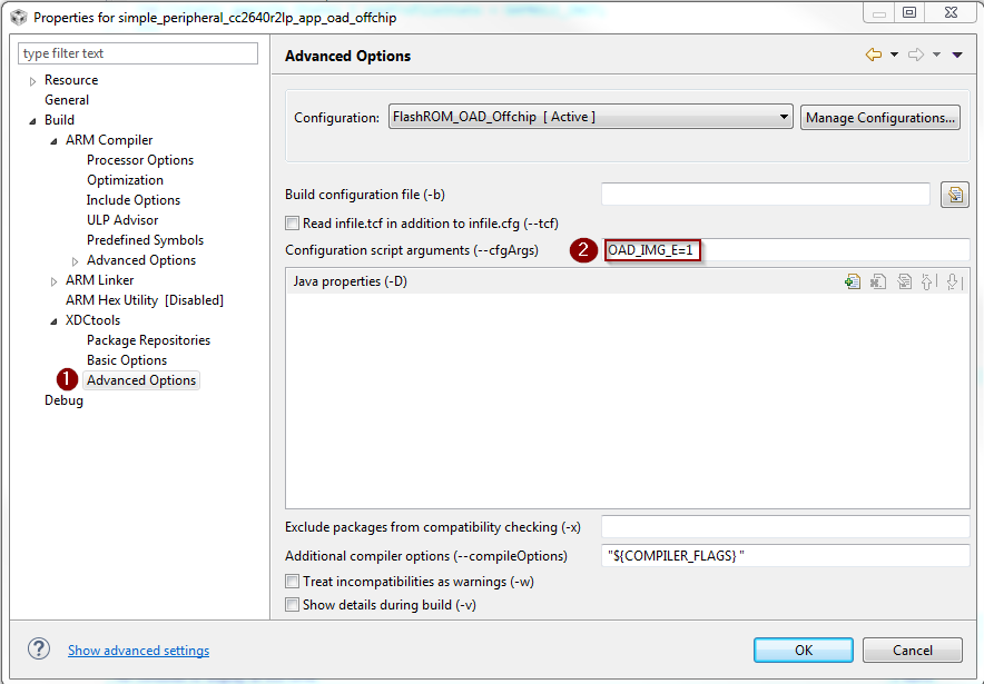
Add the necessary arguments to your configuro script to relocate your app’s reset vector address.
- Add
OAD_IMG_E=1to your –cfgArgs. See Using a custom reset vector address for your application for more information.
- Add
[Optional] On custom hardware, you may need to change the pinout of the external flash part. This can be done in two steps:
First, change the application layer code.
The application interfaces to the external SPI flash via
ExtFlash.cBy default, the ExtFlash module uses
Board_SPI0, this can be changed to Board_SPI0/* Attempt to open SPI. */ spiHandle = SPI_open(Board_SPI0, &spiParams);
The pins used by the
Board_SPIXgroup can be set in the board file, i.e. CC2640R2_LAUNCHXL.c.mosiPin = CC2640R2_LAUNCHXL_SPI1_MOSI, .misoPin = CC2640R2_LAUNCHXL_SPI1_MISO, .clkPin = CC2640R2_LAUNCHXL_SPI1_CLK, .csnPin = CC2640R2_LAUNCHXL_SPI1_CSN
The defines above can be set in CC2640R2_LAUNCHXL.h
Second, change the pins that the BIM uses to acces the SPI flash. This can be done in the
bim_oad_offchipproject. Since BIM is a bare metal program (no-RTOS). It doesn’t use the TI-RTOS SPI driver like the application does. BIM SPI pins are set in\examples\rtos\CC2640R2_LAUNCHXL\blestack\bim_oad_offchip\src\bsp.h// Board external flash defines #define BSP_IOID_FLASH_CS IOID_20 #define BSP_SPI_MOSI IOID_9 #define BSP_SPI_MISO IOID_8 #define BSP_SPI_CLK_FLASH IOID_10
On-Chip OAD
This section describes the on-chip OAD process. On-chip OAD uses only internal flash to update the user application. No external components are required. This section aims to address the following procedures that are unique to on-chip OAD:
For information about the OAD profile and metadata, please see OAD Concept Overview
Note
The terms OAD Target App and Image A are synonymous. Both refer to the image that is permanetly resident during on-chip OAD operations. The OAD Target App runs on the OAD Target device for the purposes of updating the user image (Image B).
Constraints and Requirements for On-chip OAD
In order to perform on-chip OAD the target system must contain have:
- Enough free code space to fit the user application within the 17 pages of internal flash allocated to it.
- Ability to use the split image ICall architecture. See ICall for more information.
The OAD Image to be downloaded is, by default, allocated 17 flash pages. Because page 0 cannot be updated, an application must include its own TI-RTOS instance in flash without dependence on the TI-RTOS ROM implementation. This image also shares the CCFG referenced in the above paragraph. It is not possible to update the CCFG parameters via an OAD.
The OAD Target App and the OAD image should share the same RAM range as only one is used per device reset. The OAD Image must be a complete application image, capable of running independently of the permanently resident OAD Target App.
The BLE protocol stack defaults to a range of 8 flash pages, ranging from address 0x17000 to 0x1EFFF and no SNV pages are used by default. If the OAD Image is too large to fit in its allocated space, consider removing some features of the BLE stack to reduce its size.
The OAD Target App, or the Image A, and the Image B shall share the same BLE stack. It is not possible to perform an On-chip OAD of the BLE Stack image.
On-Chip OAD Memory layout
The memory map for CC2640R2F internal flash in an on-chip OAD configuration is shown below.
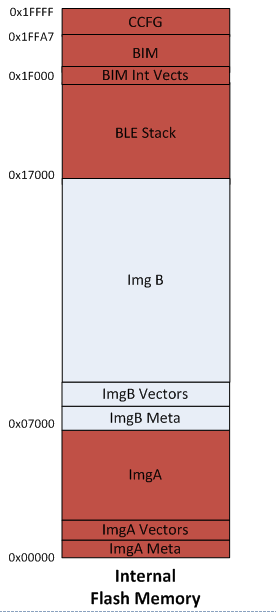
Figure 80. On-Chip OAD Memory Layout
BIM for On-chip OAD
Warning
The BIM will link the resident CCFG sector. Furthermore,
this is a custom CCFG, with the IMAGE_VALID_CONF field set to
0x1F000. This means that the boot ROM of the device will automatically
exectue BIM code instead of application code at startup. BIM
will handle starting the application. OAD applications will not need to
include a CCFG. This is a feature of CC2640R2F, and not compatible
with R1 devices.
The OAD solution requires that permanently resident boot code, the BIM, exists in order to provide a fail-safe mechanism for determining (in preferential order) the image which is ready to run. When a valid image is found, the BIM jumps to that image at which point the image takes over execution. Either Image A or Image B must implement the proprietary TI OAD Profile. By default, this is Image A’s role. When an image with the OAD Profile downloads a new image, a system reset can be executed to return to BIM to verify the correctness of the download and begin execution.
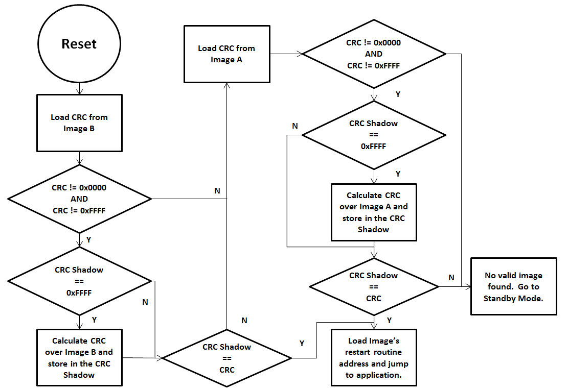
Figure 81. Functional Overview of On-chip BIM
As the permanent owner of the flash interrupt vectors, BIM provides a fail-safe mechanism for intercepting the reset vector, putting the hardware into a safe state, and taking the most appropriate action by reading the headers of Image A and Image B.
By default, BIM gives precedence to Image B, as Image A is only expected to be run when a newer instance of Image B is ready to OAD or no valid Image B exists. If the preferred image is not ready to run, then the other image is checked. If neither image is ready to run – an unlikely scenario because Image A, the OAD Target App, need not ever be erased – then BIM puts the device into a low power Standby mode. Also by default, a CRC check is not performed on Image A because it is expected that the OAD Target App will be used as a fixed image. The check on Image A will only read the checksum placed by IAR to see if an image exists, it will not calculate the CRC shadow.
In order to verify that an image is valid, a fixed 4-byte area known as the CRC and CRC-shadow will be queried. If the 2-byte CRC16 output calculated at build time matches the 2-byte CRC16 shadow calculated by BIM, then the image is commissioned to run immediately. If the CRC is not zero and not the erased-flash value of 0xFFFF and the CRC-shadow is the erased-flash value of 0xFFFF, then the CRC can be calculated over the entire image (not including this 4-byte area) and the result can be compared to the valid CRC to determine whether the image should be commissioned as ready to run.
Out of the Box Demo (On-Chip OAD)
The Simplelink CC2640R2 SDK includes demo projects that are setup to use OAD in advance. These build configurations may be flashed onto the device out of the box. All out of the box demos use BTool as the OAD Downloader. Please see OAD Topology Overview for more information. Ensure that BTool is setup correctly first. See BTool Setup for steps on how to do so. The steps listed below assume that a CC2640R2 Launchpad is being used. Additional steps may be required for custom hardware.
Furthermore, the steps in this section are referring to the OAD Target device, the images refrenced below should be flashed onto that device.
Using CCS
Warning
If both the OAD Target and the OAD Downloader are connected at the same time, CCS may load the image to the wrong device. This is because CCS will select the first XDS110 it finds. This behavior can be avoided by unplugging the OAD Target device, or by setting a multi emulator debug session using CCS. See the wiki Debug with Multiple Emulators for more information.
Import the
bim_oad_onchip,oad_target_cc2640r2lp_stack,oad_target_cc2640r2lp_app, andsimple_peripheral_cc2640r2lp_app_oad_onchipprojects into the workspace.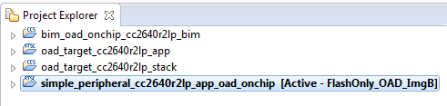
Figure 82. On-chip OAD CCS Workspace
Build the
bim_oad_onchipandoad_target_cc2640r2lp_stackprojects.Follow the instructions at Generating a Production Image for OAD to generate a superbin of BIM, OAD Target Stack, and OAD Target App.
Load the supebin created in the previous step onto the CC2640R2 Launchpad using Smart RF Flash Programmer 2.
- Make sure you are using the *_oad.bin file with BTool as this file
contains the metadata. By default these images can be found at:
\workspace_v7\oad_target_cc2640r2lp_app - Make sure to erase all unprotected pages so any old code in the image B region is removed.
- Make sure you are using the *_oad.bin file with BTool as this file
contains the metadata. By default these images can be found at:
You should now be able to observe that the device is advertising via BTool.
- The OAD Target App (Image A) advertises as “OAD Target”, it’s device
addr is
0A:D0:AD:0A:D0:AD. - See BTool OAD Verify Advertising for steps.
- The OAD Target App (Image A) advertises as “OAD Target”, it’s device
addr is
Make your application level changes that are intended for OAD update. Follow steps in Changing Application Data to Verify an OAD for a trivial way to change app to verify the OAD. Build the application with changes.
- Remember that with the ImageA/ImageB architecture of on-chip OAD, the user
space application is
simple_peripheral_cc2640r2lp_app_oad_onchipchanges should be made to this application as Image A is permanetly resident and cannot be updated.
- Remember that with the ImageA/ImageB architecture of on-chip OAD, the user
space application is
Use BTool to OAD your modified application file following the steps detailed in BTool OAD Procedure
- Make sure you are using the *_oad.bin file with BTool as this file
contains the metadata. By default these images can be found at:
\workspace_v7\simple_peripheral_cc2640r2lp_app_oad_onchip
- Make sure you are using the *_oad.bin file with BTool as this file
contains the metadata. By default these images can be found at:
Attention
After a successful OAD, you may need to re-start your CC2640R2F in order for it to advertise again. This is because the XDS110 driver may be still attached from previous debug sessions.
Using IAR
Open
bim_oad_onchipworkspace, build the project.Open
oad_targetworkspace, build the stack project.Follow the instructions at Generating a Production Image for OAD to generate a superbin of BIM, OAD Target Stack, and OAD Target App.
Load the supebin created in the previous step onto the CC2640R2 Launchpad using Smart RF Flash Programmer 2.
- Make sure you are using the *_oad.bin file with BTool as this file
contains the metadata. By default these images can be found at:
\examples\rtos\CC2640R2_LAUNCHXL\blestack\oad_target\tirtos\iar\app\FlashROM\Exe - Make sure to erase all unprotected pages so any old code in the image B region is removed.
- Make sure you are using the *_oad.bin file with BTool as this file
contains the metadata. By default these images can be found at:
You should now be able to observe that the device is advertising via BTool.
- The OAD Target App (Image A) advertises as “OAD Target”, it’s device
addr is
0A:D0:AD:0A:D0:AD. - See BTool OAD Verify Advertising for steps.
- The OAD Target App (Image A) advertises as “OAD Target”, it’s device
addr is
Make your application level changes that are intended for OAD update. Follow steps in Changing Application Data to Verify an OAD for a trivial way to change app to verify the OAD. Build the application with changes.
- Remember that with the ImageA/ImageB architecture of on-chip OAD, the user
space application is
simple_peripheralwith the FlashOnly_OAD_ImgB build config. Changes should be made to this application as Image A is permanetly resident and cannot be updated.
- Remember that with the ImageA/ImageB architecture of on-chip OAD, the user
space application is
Use BTool to OAD your modified application file following the steps detailed in BTool OAD Procedure
- Make sure you are using the *_oad.bin file with BTool as this file
contains the metadata. By default these images can be found at:
\examples\rtos\CC2640R2_LAUNCHXL\blestack\simple_peripheral\tirtos\iar\app\FlashROM_OAD_Offchip\Exe - The simple_peripehral app (Image B) advertises as “Simple BLE Peripheral”, it’s device addr is the default burned into the device during production.
- Make sure you are using the *_oad.bin file with BTool as this file
contains the metadata. By default these images can be found at:
Attention
After a successful OAD, you may need to re-start your CC2640R2F in order for it to advertise again. This is because the XDS110 driver may be still attached from previous debug sessions.
Add On-Chip OAD to an existing project
Use OAD Target/ ImageA Project, as is. No change is required. This includes:
bim_oad_onchipoad_target_cc2640r2lp_stackoad_target_cc2640r2lp_app
Add OAD profile code to the application project:
- The required files can be found in
examples\rtos\CC2640R2_LAUNCHXL\blestack\profiles\oad\cc26xxoad.coad.hoad_target.hoad_target_internal_flash.coad_reset_service.c
- The required files can be found in
Add the necessary include paths to the project:
- The OAD profile code can be found at
examples\rtos\CC2640R2_LAUNCHXL\blestack\profiles\oad\cc26xx
- The OAD profile code can be found at
Add the following defines to your application:
- IMAGE_INVALIDATE
- HAL_IMAGE_B
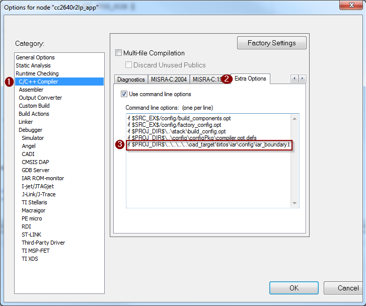
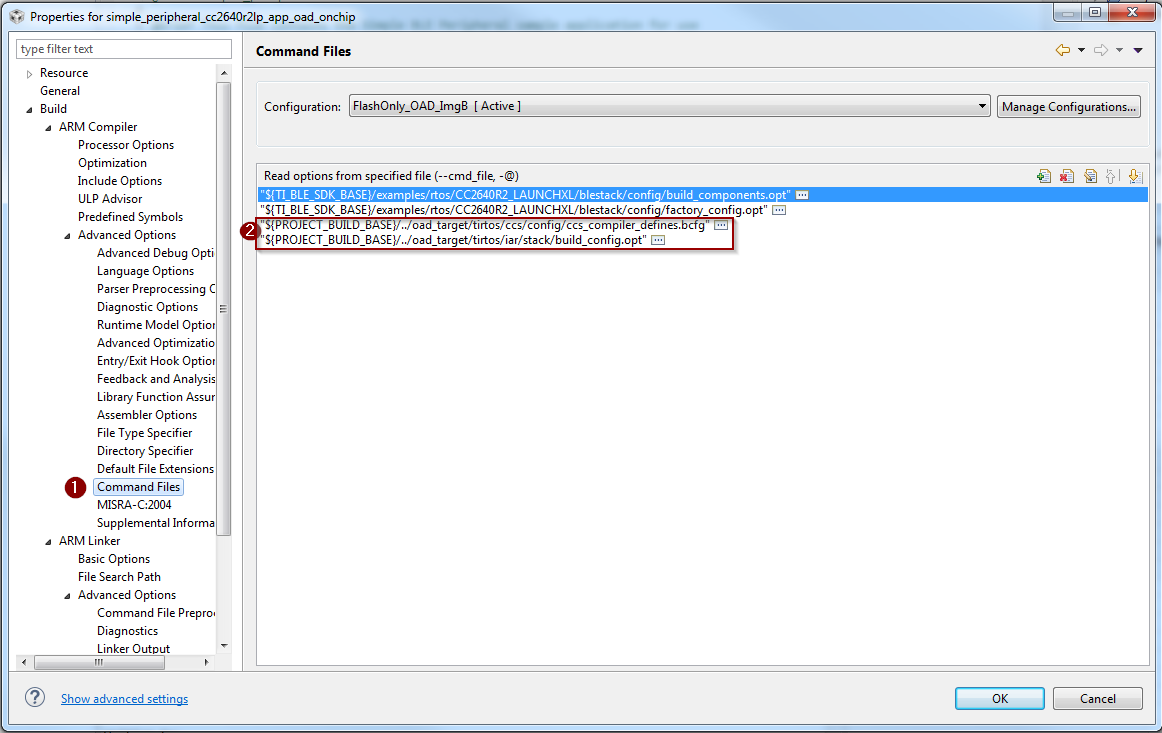
Add the OAD Target Stack’s boundary definition See screenshots below.
- IAR
- CCS
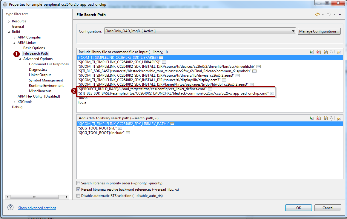
Use the proper on-chip OAD linker file and configure it properly.
IAR projects should use
cc26xx_app_oad.icfPass in the following defines to the linker:
- CC2650=2
- FLASH_ONLY_BUILD=2
Add the OAD Target Stack’s boundary definition See screenshot below.
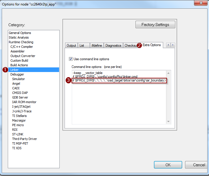
CCS projects should use
cc26xx_app_oad_onchip.cmd- Pass in the following defines to the linker:
- R2=1
- Pass in the following defines to the linker:
Add the OAD Target Stack’s boundary definition See screenshot below.
Add necessary code to your high level application file to include the OAD reset service. This service is used to invalidate Image B and jump back to Image A for further upgrades to Image B.
Add the following defines to your application file (i.e. simple_peripheral)
#include "oad_target.h"
#include "oad.h"
...
Within the application’s init routine, add the OAD reset service.
Reset_addService();
Add the necessary arguments to your configuro script to relocate your app’s reset vector address.
- Add
OAD_IMG_B=1to your –cfgArgs. See Using a custom reset vector address for your application for more information.
- Add
103.. _sec-oad-troubleshooting:
Troubleshooting Guide
This guide seeks to address many of the common issues encountered during OAD.
General Troubleshooting Guide Prior to BIM
There are various places where OAD can fail; use the following steps to determine where the issue is occurring during the interaction:
Use a BLE Packet Sniffer and Record the OAD Transaction
This will verify that the profile is implemented correctly and a valid image was transferred over the air.
Look for a OAD Initiation
Notifications from OAD Image Notify should be requested – and the appropriate response from the OAD Target after a GATT Write of the Candidate metadata.
Look for OAD Image Status Characteristic
This will contain the status of the image prior to BIM launching the image.
Read external/internal flash to ensure CRC Shadow is valid and matches CRC field
This will verify that the image was received fully without errors by the OAD Target
- For Internal, various tools can be used. SmartRF Programmer 2 or using a jtag debugger and connecting to running target and utilizing a memory viewer are possible options.
- For External, interface another MCU or another serial device to dump out the Flash.
Downloaded OAD Image Isn’t Starting
If the application doesn’t start running the downloaded firmware after a successful download, it’s a BIM issue.
Depending on OAD type, on-chip or off-chip, refer to sections BIM for On-chip OAD or BIM for Off-chip OAD respectively. Utilize how BIM operates and a debugger to find where the issue is occurring.
Should External Flash be Used During OAD?
No, External flash should not be utilized while OAD Profile is active; the Profile is designed to have uninterrupted access to Flash, in Off-Chip configurations.
Building Super Hex Files
To build merged hexfiles, there are various methods to do this. One option is to utilize the TI OAD Image Tool (Python). See Generating a Production Image for OAD for more information.
Mobile Application Can’t Perform OAD
Ensure the latest version of the Application is downloaded from your Phone’s Application Store and try again.
If problem persists, please post your Phone’s Model and OS Version number along with details to reproduce your setup on our Support Forums. Utilize BTool and verify that the OAD works correctly.
Can’t connect via BTool After successful OAD
- Try resettting the
host_testdevice attached to BTool. - Close and re-open BTool.
- Verify target is advertising using a mobile app.
OAD Target App Doesn’t Advertise out of the Box
Likely the image metadata is not embedded in the image, or there is a corrupted image that is causing problems.
- Perform a forced mass erase using Smart RF Flash Programmer 2
- Follow the steps at Out of the Box Demo (On-Chip OAD), particularly Generating a Production Image for OAD
Appendix
This section will cover various tutorials that are helpful throughout the OAD process. It is not intended to be read sequentially, but instead refrenced from other sections.
Generating a Production Image for OAD
A production image is one that contains the app, stack, and bootloader images combined into a single file. Production images are generally used when an OAD enabled device is sent off for production at the factory. They can also be useful for debugging as all of the information is contained in a single file.
TI has included a Python based OAD Image Tool that can perform a variety of operations on OAD ready hex files in the Simplelink CC2640R2 SDK. It will be used to generate a production OAD image.
Currently, the oad_image_tool is already being invoked as a post build step on oad_target_app, and simple_peripheral buils for on and off-chip OAD.
CCS Update OAD Image Tool Build Step
The image below shows how to edit the CCS post build step for the OAD image tool. This menu can be accessed by right clicking the project –> properties.
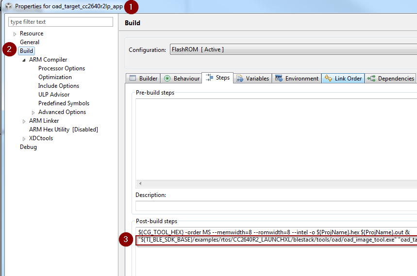
Figure 87. Update OAD Image Tool Post Build Step CCS
IAR Update OAD Image Tool Build Step
The image below shows how to edit the IAR post build step for the OAD image tool. This menu can be accessed by right clicking the project –> options.
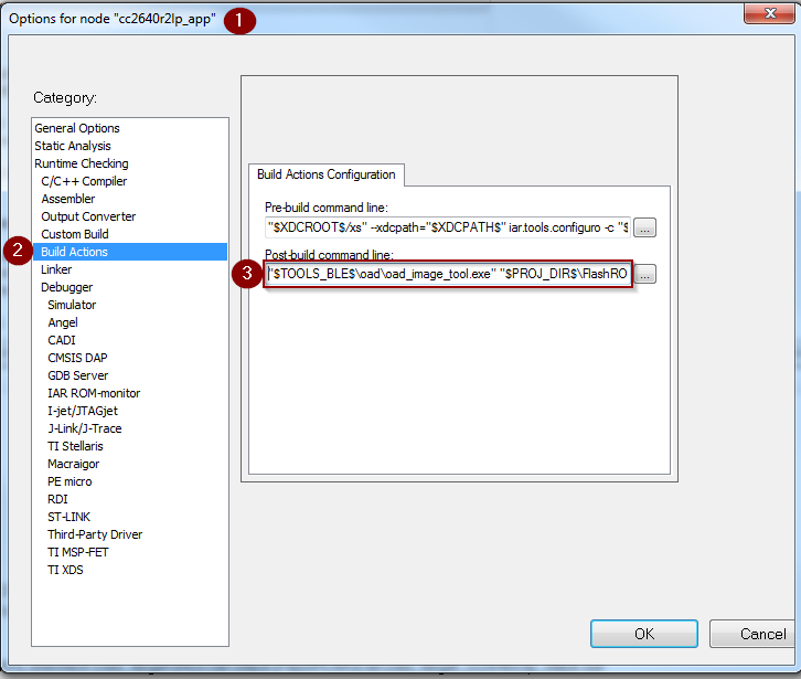
Figure 88. Update OAD Image Tool Post Build Step IAR
Generate production On-Chip (Image A) using CCS
The following steps detail how to generate an on-chip OAD production image which contains Image A and the on-chip BIM.
Warning
The following steps assume you have already followed the steps 1-2 of the Out of the Box Demo (On-Chip OAD) for CCS.
Add the following code to the
oad_target_cc2640r2lp_appproject’s post build steps."${TI_BLE_SDK_BASE}/examples/rtos/CC2640R2_LAUNCHXL/blestack/tools/oad/oad_image_tool.exe" "oad_target_cc2640r2lp_app.hex" "${PROJECT_LOC}/../oad_target_cc2640r2lp_stack/FlashROM/oad_target_cc2640r2lp_stack.hex" "${PROJECT_LOC}/../bim_oad_onchip_cc2640r2lp_bim/FlashOnly/bim_oad_onchip_cc2640r2lp_bim.hex" -t onchip -i production -v 0 --usrId AAAA -ob "${ProjName}_oad.bin"
Generate production On-Chip (Image A) using IAR
The following steps detail how to generate an on-chip OAD production image which contains Image A and the on-chip BIM.
Warning
The following steps assume you have already followed the steps 1-2 of the Out of the Box Demo (On-Chip OAD) for IAR.
Add the following code to the
oad_target_cc2640r2lp_appproject’s post build steps."$TOOLS_BLE$\oad\oad_image_tool.exe" "$PROJ_DIR$\..\..\..\..\bim_oad_onchip\tirtos\iar\app\FlashOnly\Exe\bim_oad_onchip_cc2640r2lp_bim.hex" "$PROJ_DIR$\..\stack\FlashROM\Exe\oad_target_cc2640r2lp_stack.hex" "$PROJ_DIR$\FlashROM\Exe\oad_target_cc2640r2lp_app.hex" -t onchip -i production -v 0 --usrId AAAA -ob "$PROJ_DIR$\FlashROM\Exe\oad_target_cc2640r2lp_app_oad.bin"
Generate production Off-Chip using CCS
The following steps detail how to generate an on-chip OAD production image which contains Image A and the on-chip BIM.
Warning
The following steps assume you have already followed the steps 1-2 of the Out of the Box Demo (On-Chip OAD) for CCS.
Add the following code to the
oad_target_cc2640r2lp_appproject’s post build steps."${TI_BLE_SDK_BASE}/examples/rtos/CC2640R2_LAUNCHXL/blestack/tools/oad/oad_image_tool.exe" "${ProjName}.hex" "${PROJECT_LOC}/../simple_peripheral_cc2640r2lp_stack/FlashROM/simple_peripheral_cc2640r2lp_stack.hex" "${PROJECT_LOC}/../bim_oad_offchip/FlashOnly/bim_oad_offchip.hex" -t onchip -i production -v 0 -m 0x0000 -ob "${ProjName}_oad.bin"
Generate production Off-Chip Image using IAR
The following steps detail how to generate an on-chip OAD production image which contains Image A and the on-chip BIM.
Warning
The following steps assume you have already followed the steps 1-2 of the Out of the Box Demo (On-Chip OAD) for IAR.
Add the following code to the
oad_target_cc2640r2lp_appproject’s post build steps."$TOOLS_BLE$\oad\oad_image_tool.exe" "$PROJ_DIR$\..\..\..\..\bim_oad_offchip\tirtos\iar\app\FlashOnly\Exe\bim_oad_offchip.hex" "$PROJ_DIR$\..\stack\FlashROM\Exe\simple_peripheral_cc2640r2lp_stack.hex" "$PROJ_DIR$\FlashROM_OAD_Offchip\Exe\simple_peripheral_cc2640r2lp_app.hex" -t onchip -i production -v 0 -m 0x0000 -ob "$PROJ_DIR$\FlashROM_OAD_Offchip\Exe\simple_peripheral_cc2640r2lp_app_oad.bin"
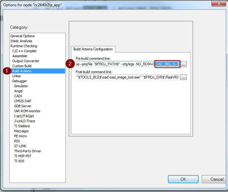
Using a custom reset vector address for your application
The projects within the Simplelink CC2640R2 SDK will build the TI-RTOS kernel as a pre-build step within the application. This prebuild step is called configuro. During the configuro stage it is possible to relocate your reset vectors. This is required for OAD applications to make room for the metadata vector at the beginning of the image space. For more information about configuro, please see RTSC Configuro Page.
Note
You may need to change OAD_IMG_E=1 in the images below
to OAD_IMG_A=1 or OAD_IMG_B=1 depending on your use case.
Change Reset Vector Address in IAR
IAR treats configuro as a prebuild action. These actions can be found by right clicking the project –> Build Actions –> Pre-build command line. See the image below for more information.
Change Reset Vector Address in CCS
CCS has native RTSC/Configuro support built into the project. These actions can be found by right clicking the project –> Build –> XDCtools –> Advanced Options. See the image below for more information.
Changing Application Data to Verify an OAD
It can be difficult to verify OAD without making application changes. A quick and easy way to change your application image before sending over the air is to change it’s scan response data.
This way, a successful OAD can be observed via the change in scan response data. See below for steps on how to change this.
- A good test is to change the scan response data as below in
simple_peripheral.c
Warning
If you change of scan response data you must also change it’s length. See line 5 of the code snippet above.
Using BTool
This section will describe how to use setup and use BTool, to perform an OAD. These steps are independent of OAD type and can be used to perform on or offchip OAD.
Tip
BTool is a very feature-rich application. This guide only seeks to document the OAD functionality of BTool.
BTool Setup
BTool requires a CC2640R2 Launchpad running the host_test application with
POWER_SAVING disabled connected to the PC. Steps on how to setup a
CC2640R2 Launchpad to work with BTool are listed below. See OAD Topology Overview for more
information.
- Navigate to the install location of the Simplelink CC2640R2 SDK.
- Within the Simplelink CC2640R2 SDK open the
\examples\rtos\CC2640R2_LAUNCHXL\blestack\hexfilesfolder. - Open Smart RF Flash Programmer 2.
- Load one the OAD Downloader CC2640R2 Launchpad with the
cc2640r2lp_host_test.heximage.
BTool OAD Verify Advertising
BTool can be used to scan and discover OAD device. You can verify your device is advertising by following one of the options below.
- Advertisement can be verified in one of two ways:
- If you know your device’s address (can be checked via Smart RF Flash Programmer 2) you can click the scan button and verify it appears in the “Slave BDA” combo box.
- If you don’t know your device’s address, you can change it’s advertisement data (described in Changing Application Data to Verify an OAD). From there, scan the scan button and look in the BTool log window during scanning to verify the device with the custome advertising data appears.
BTool OAD Procedure
Open BTool, and connect to your device. See the image below for steps.
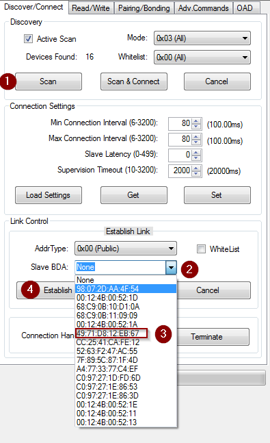
Figure 91. Connecting to a device using BTool
Select to the OAD tab in BTool and initiate the OAD process. See the image below for instructions
Attention
Be sure to point BTool to the *_oad.bin file generated by the oad image tool post build step. This file contains the metadata.
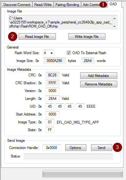
Figure 92. Initiating an OAD transfer via BTool
OAD process will continue as below
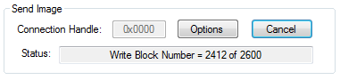
Figure 93. OAD transfer via BTool
BTool will report success
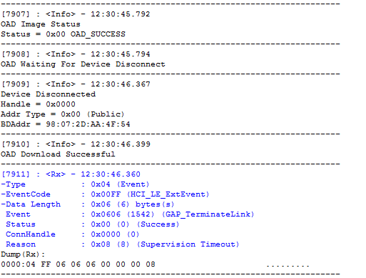
Figure 94. Successful OAD transfer using BTool