The CC2640R2F Platform
Architecture
The TI royalty-free Bluetooth low energy software development kit (SDK) is a complete software platform for developing single-mode Bluetooth low energy applications. This kit is based on the SimpleLink CC2640R2F, complete System-on-Chip (SoC) Bluetooth low energy solution. The CC2640R2F combines a 2.4-GHz RF transceiver, 128-KB in-system programmable memory, 20KB of SRAM, and a full range of peripherals. The device is centered on an ARM® Cortex®-M3 series processor that handles the application layer and Bluetooth low energy protocol stack and an autonomous radio core centered on an ARM Cortex®-M0 processor that handles all the low-level radio control and processing associated with the physical layer and parts of the link layer. The sensor controller block provides additional flexibility by allowing autonomous data acquisition and control independent of the Cortex-M3 processor, further extending the low-power capabilities of the CC2640R2F. Figure 2. shows the block diagram. For more information on the CC2640R2F, see the CC26xx Technical Reference Manual.
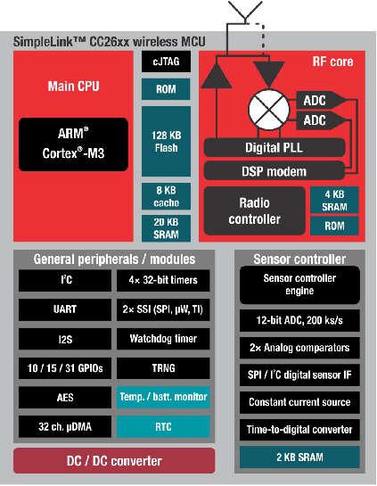
Figure 2. SimpleLink CC2640R2F Block Diagram
Hardware and Software Architecture
This section aims to introduce the different cores within the CC2640R2F, how they interact, and the firmware that runs on them. The information presented here should be considered as an overview. For detailed descriptions of the hardware described here, refer to the chapter 23 of the CC26xx Technical Reference Manual.
ARM Cortex M0 (Radio Core)
The Cortex M0 (CM0) core within the CC2640R2F is responsible for both interfacing to the radio hardware, and translating complex instructions from the Cortex M3 (CM3) core into bits that are sent over the air using the radio. For the Bluetooth low energy protocol, the CM0 implements the PHY layer of the protocol stack. Often, the CM0 is able to operate autonomously, which frees up the CM3 for higher-level protocol and application-layer processing.
The CM3 communicates with the CM0 through a hardware interface called the RF doorbell, which is documented in section 23.2 of the CC26xx Technical Reference Manual. The radio core firmware is not intended to be used or modified by the application developer.
ARM Cortex M3 (System Core)
The system core (CM3) is designed to run the Bluetooth low energy protocol stack from the link layer up to the user application. The link layer interfaces to the radio core through a software module called the RF driver, which sits above the RF doorbell. The RF driver runs on the CM3 and acts as an interface to the radio on the CC2640R2F, and also manages the power domains of the radio hardware and core. Documentation for the RF driver can be found at the TI Driver API Reference. Above the RF driver is the TI Bluetooth low energy protocol stack, which is implemented in library code.
The application developer should interface with the stack through a set of APIs (ICall) to implement an end use case. The rest of this document intends to document application development on the CC2640R2F using the Bluetooth low energy stack.
BLE-Stack Protocol Stack and Application Configurations
Figure 3. shows the platform that supports two different protocol stack and application configurations.
- Single device: The controller, host, profiles, and application are all implemented on the CC2640R2F as a true single-chip solution. This configuration is the simplest and most common when using the CC2640R2F. This configuration is used by most of TI’s sample projects. This configuration is the most cost-effective technique and provides the lowest-power performance.
- Simple network processor: The Simple Network Processor (SNP) implements the controller and host layers of the BLE-Stack. Additionally, the SNP exposes an interface for scheduling communication between the stack and an external MCU. This accelerates dual MCU designs because the application processor (AP) is only responsible for managing custom profiles and application code. Stack-related functionality, such as security, is implemented on the SNP. The SNP currently supports the peripheral and broadcaster GAP roles. Communication with the SNP is carried out through the SNP API. The SNP API is built on the Unified Network Processor Interface (UNPI), which supports UART and SPI transport layers. For more information, reference the Unified Network Processor Interface wiki page. TI also provides the SAP library, which implements a UNPI master and the SNP API. The SAP library can be ported to any TI-RTOS-capable processor, or used as a reference for developing a custom dual MCU solution. For a description of the SNP, see the CC2640R2F Simple Network Processor API Guide CC2640R2F Simple Network Processor API Guide.
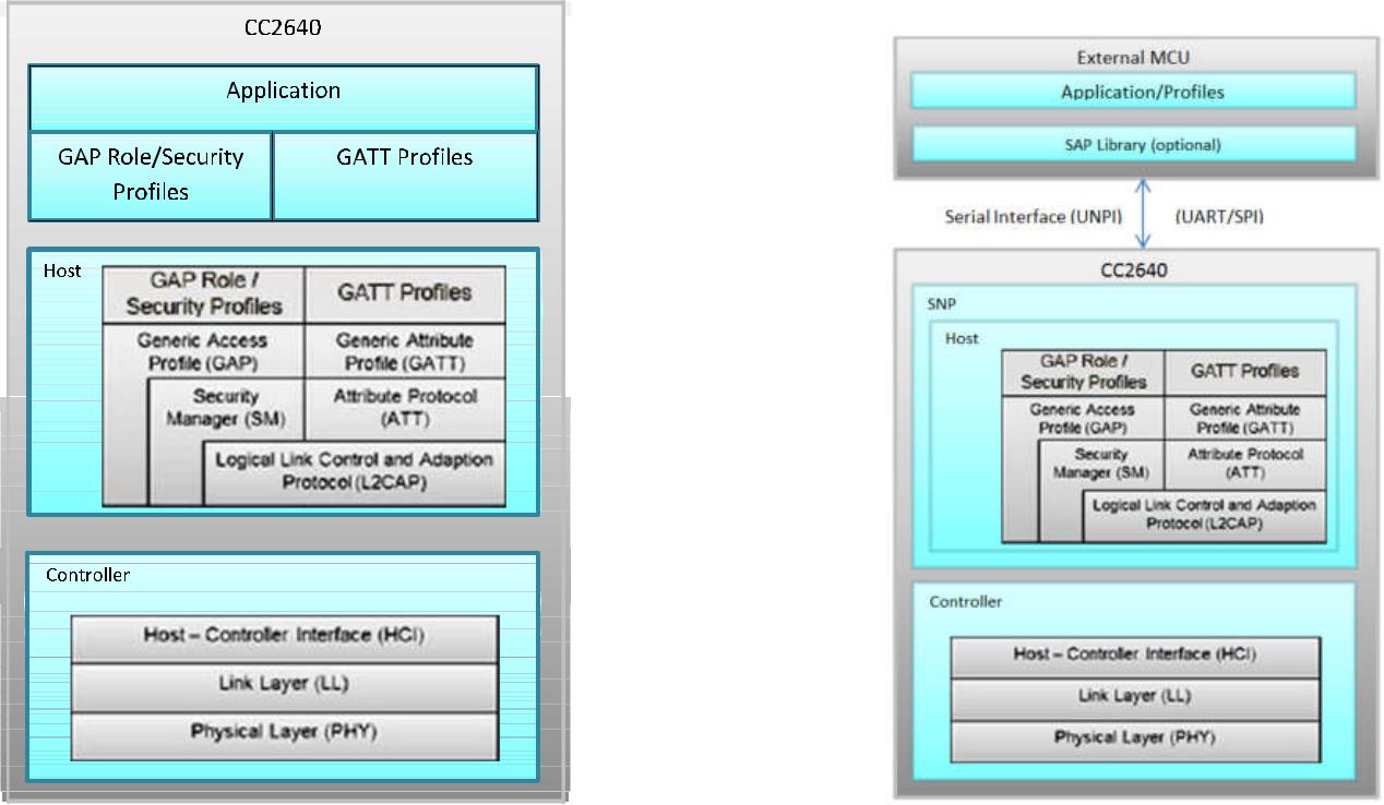
Figure 3. Single-Device Processor and Simple Network Processor Configurations
Solution Platform
This section describes the various components that are installed with the BLE-Stack 3.00.00 and the directory structure of the protocol stack and any tools required for development. Figure 4. shows the BLE-Stack 3.00.00 development system.
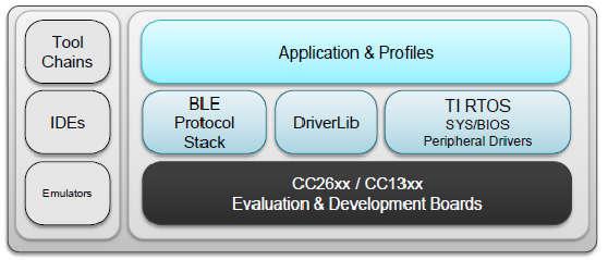
Figure 4. Bluetooth low energy Stack Development System
The solution platform includes the following components:
- TI’s Real-Time Operating System (TI-RTOS) with the TI-RTOS kernel, optimized power management support, and peripheral drivers (SPI, UART, and so forth)
- CC26xxware DriverLib provides a register abstraction layer and is used by software and drivers to control the CC2640R2F SoC.
- The Bluetooth low energy protocol stack is provided in library form with parts of the protocol stack in the CC2640R2F ROM.
- Sample applications and profiles make starting development using both proprietary and generic solutions easier.
The following integrated development environments (IDEs) are supported:
- IAR Embedded Workbench for ARM
- Code Composer Studio™ (CCS)
Refer to the SDK release notes for the specific IDE versions supported by this release.
Example Software Architecture
The CC2640R2F Bluetooth low energy software environment consists of the following parts:
- TI-RTOS
- An application image
- A stack image
TI-RTOS is a real-time, pre-emptive, multithreaded operating system that runs the software solution with task synchronization. Both the application and Bluetooth low energy protocol stack exist as separate tasks within the RTOS. The Bluetooth low energy protocol stack has the highest priority. A messaging framework called indirect call (ICall) is used for thread-safe synchronization between the application and stack. Figure 5. shows the architecture.
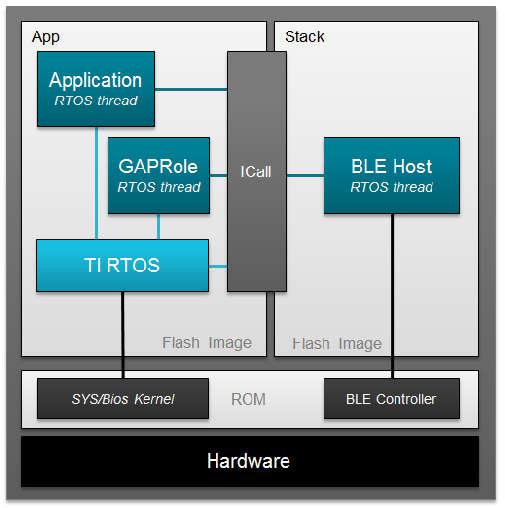
Figure 5. Example Software Architecture
- The stack image includes the lower layers of the Bluetooth low energy protocol stack from the LL up to and including the GAP and GATT layers. Most of the Bluetooth low energy protocol stack code is provided as a library.
- The application image includes the profiles, application code, drivers, and the ICall module.
Stack Library Configuration
In BLE-Stack 3.00.00, the application can consume the stack project in a library form. Projects with build with this new configuration can be identified by project build configurations with Library in its configuration name. Using this build configuration will yield significant flash footprint optimizations by the linker. The gained footprint savings will however prevent split-image application- or stack-only OAD downloads. See Available CCS project build configurations and Available IAR project build configurations for the available project build configurations.
Split Image Configuration
As with previous BLE-Stack 2.x releases, application and stack images is built as two separate projects that generate two separate image binaries. This configuration is useful in purposes such as OAD where it could be advantageous to perform independent application or stack downloads. With this configuration, application and stack images have flash boundary constraints. Based on this design, projects built in this configurationwill consume more flash than applications configured to link with the stack library configuration.
Standard Project Task Hierarchy
Considering the simple_peripheral project as an example, these tasks are listed by priority. A higher task number corresponds to a higher priority task:
- Priority 5: Bluetooth low energy protocol stack task
- Priority 3: GapRole task (peripheral role)
- Priority 1: Application task (simple_peripheral)
TI-RTOS Overview introduces TI-RTOS tasks. Overview describes interfacing with the Bluetooth low energy protocol stack. GAPRole Task describes the GapRole task. Pre-main initialization describes the application task.
Directory Structure
The default install location is: C:\ti\simplelink_cc2640r2_sdk_x_xx_xx_xx.
The SDK installs to this location by default. For the purposes of this document, consider the above path to the BLE-Stack root directory; it will be omitted. All paths will be relative to the BLE-Stack root directory. Opening up the root install directory shows the new parent folders within the SDK, as shown in Table 1.
| BLE-Stack 3.00.00 folders | Purpose |
|---|---|
| docs\ | The docs directory now contains all relevant documents included with the CC2640R2F SDK. |
| examples\ | The CC2640R2F SDK includes ble examples as well as TI-RTOS kernel and TI-RTOS driver examples. |
| kernel\ | The TI-RTOS kernel is now included with the CC2640R2F SDK. |
| source\ | The source\ directory include source for BLE-Stack, TI-RTOS kernel and drivers, and various middleware modules. |
| tools\ | Tools such as BTool |
Examples Folder
The examples\ folder contains example source files for the BLE-Stack, TI-RTOS kernel, and TI-RTOS drivers. All the source code supporting the Simplelink CC2640R2 SDK examples can be found at *examples\rtos\CC2640R2_LAUNCHXL\. Examples for each product can be found within their respective folders and are accessible via various means as shown in Examples available for the CC2640R2F platform.
| Type of examples | Example subdirectory | How to open the examples |
|---|---|---|
| BLE-Stack | blestack\ | Imported via TI Resource Explorer
Opened as existing IAR projects
|
| TI-RTOS Kernel | sysbios\ | |
| TI-RTOS Drivers | drivers\ |
For TI-RTOS Kernel and TI-RTOS driver examples, see the linked documentation. To help select a specific BLE example see BLE examples available for the CC2640R2F platform. As with previous BLE-Stack releases, each example contains a toolchain subdirectory for CCS and IAR.
| Example | Location |
|---|---|
| BIM OAD Off-chip | *examples\rtos\CC2640R2_LAUNCHXL\blestack\ bim_oad_offchip \tirtos\ |
| BIM OAD On-chip | *examples\rtos\CC2640R2_LAUNCHXL\blestack\ bim_oad_onchip \tirtos\ |
| Host Test Project | *examples\rtos\CC2640R2_LAUNCHXL\blestack\ host_test \tirtos\ |
| Micro Eddystone Beacon | *examples\rtos\CC2640R2_LAUNCHXL\blestack\ micro_eddystone_beacon \tirtos\ |
| Multi Role | *examples\rtos\CC2640R2_LAUNCHXL\blestack\ multi_role \tirtos\ |
| OAD Target | *examples\rtos\CC2640R2_LAUNCHXL\blestack\ oad_target \tirtos\ |
| Simple Broadcaster | *examples\rtos\CC2640R2_LAUNCHXL\blestack\ simple_broadcaster \tirtos\ |
| Simple Central | *examples\rtos\CC2640R2_LAUNCHXL\blestack\ simple_central \tirtos\ |
| Simple Observer | *examples\rtos\CC2640R2_LAUNCHXL\blestack\ simple_observer \tirtos\ |
| Simple Peripheral | *examples\rtos\CC2640R2_LAUNCHXL\blestack\ simple_peripheral \tirtos\ |
IAR examples are available as .eww projects whereas CCS project are imported.
The remaining subdirectories in *examples\rtos\CC2640R2_LAUNCHXL\blestack\ are associated support files. Their purpose are solely for BLE-Stack examples and are explained in BLE example support files.
| Support files | Purpose |
|---|---|
| boards\ | TI-RTOS board files similar to those found in source\ti\boards (which are use for TI-RTOS kernel and driver examples). The board files found here have altered to suite BLE-Stack example requirements. |
| common\ | Common source files used by BLE-Stack examples. |
| config\ | TI-RTOS .cfg configuration files used by BLE-Stack examples. |
| hexfiles\ | Pre-compiled hex files for example projects. |
| icall\ | An ICall implementation use by BLE-Stack exmaples. |
| inc\ | Support files for BLE-Stack |
| profiles\ | Contains GATT profiles and GAP roles used by BLE-Stack examples. |
| target\ | A legacy layer of indirection to board files in boards\ |
| tools\ | Tools specific to BLE-Stack examples. |
Source Folder
The source\ti\ folder contains libraries and source files for the BLE-Stack, TI-RTOS drivers, and various shared modules. They can be found within their respective folders as shown in CC2640R2F SDK’s source\ti\ directory.
| source\ti\ | subdirectory | Purpose |
|---|---|---|
| blestack\ | Root source directory for the BLE-Stack | |
| blelib\ | Prebuilt BLE-Stack libraries | |
| controller\ | Header files for the BLE controller layer | |
| hal\ | Hardware abstraction layer files for Stack | |
| heapmgr\ | BLE-Stack Heap Manager | |
| host\ | Header files for the BLE host layters | |
| icall\ | Source files for the ICall module | |
| inc\ | Header files used to interface with the BLE-Stack | |
| microstack\ | Source files for the Micro BLE Stack | |
| npi\unified\ | Source files for the UNPI module | |
| osal\ | Source support files used by the BLE-Stack | |
| rom\ | BLE-Stack ROM symbol file | |
| services\ | Miscellaneous support files | |
| symbols\ | ROM patch support files | |
| boards\ | TI-RTOS kernel and drivers example board files | |
| devices\ | Support files from driverlib | |
| display\ | Display module | |
| drivers\ | TI-RTOS drivers source and libraries | |
| grlib\ | Graphics library (not used by BLE-Stack examples) | |
| mw\ | Other middleware modules dependent on TI-RTOS drivers | |
Working With Hex Files
BLE-Stack projects have build configurations in which the application and stack projects to produce an Intel®-extended hex file in their respective output folders. These hex files lack overlapping memory regions and can be programmed individually with a flash programming tool, such as SmartRF Flash Programmer 2. You can combine the application and stack hex files into a super hex file manually or using free tools. Information on the Intel Hex standard.
One example for creating the super hex file is with the IntelHex python script hex_merge.py, available at here. To merge the hex files, install Python® 2.7.x and add it to your system path environment variables.
The following is an example usage to create a merged simple_peripheral_cc2640r2lp.hex file consisting of the individual application and stack hex files:
1 2 3 4 5 6 | C:\Python27\Scripts>python hexmerge.py \
-o .\simple_peripheral_cc2640r2lp_merged.hex \
-r 0000:1FFFF
simple_peripheral_cc2640r2lp_app.hex:0000:1FFFF
simple_peripheral_cc2640r2lp_stack.hex
--overlap=error
|
Programming Internal Flash With the ROM Bootloader
The CC2640R2F internal flash memory can be programmed using the bootloader in the ROM of the device. Both UART and SPI protocols are supported. For more details on the programming protocol and requirements, see the Bootloader chapter of the CC26xx Technical Reference Manual.
Note
Because the ROM bootloader uses predefined DIO pins for internal flash programming, allocate these pins in the layout of your board. For details on the pins allocated to the bootloader based on the chip package type, see CC26xx Technical Reference Manual.
Installing BLE-Stack 3.00.00
The BLE-Stack 3.00.00 is a wireless component included as part of the Simplelink CC2640R2 SDK. All path and file references in this document assume that the Simplelink CC2640R2 SDK is installed to the default path (<SDK_INSTALL_DIR>).
TI recommends making a backup copy of the Simplelink CC2640R2 SDK before to making any changes. The BLE-Stack 3.00.00 uses paths relative to the Simplelink CC2640R2 SDK and therefore is portable in respect to any valid installation path for the Simplelink CC2640R2 SDK.
Attention
Code Composer Studio creates an dynamic installation variable for a discovered Simplelink CC2640R2 SDK instances. For more information, see Discovering CCS products.
Note
If installing the Simplelink CC2640R2 SDK to a nondefault path, do not exceed the maximum length of the file system namepath. Actual paths may differ from the figures.
Simplelink CC2640R2 SDK also installs XDCTools if not already present. See the release notes for required version numbers. Newer versions of tools may not be compatible with this SDK release. Check the TI Bluetooth LE Wiki for the latest supported tool versions.
Developing with CCS
Installing Code Composer Studio (CCS)
The CCS toolchain contains many features beyond the scope of this document. More information and documentation can be found here.
Check the BLE-Stack 3.00.00 release notes to see which CCS version to use and any required workarounds. Object code produced by CCS may differ in size and performance as compared to IAR produced object code.
The following procedure describes installing and configuring the correct version of CCS and the necessary tools.
Install Code Composer Studio for ARM
- Download Code Composer Studio
- Start the instllation process and accept the license agreement. It is recommended to install CCS in its default location.
- In the Processor Support section, select Simplelink CC13xx and CC26xx Wireless MCUs.
- Under the Debug Probes section, CCS will install support for TI XDS Debug Probe Support. This option supports the XDS110 debugger.
- Start the installation by selecting Finish.
Attention
The version required is stated in the release notes.
Verify ARM Compiler Tools version
- If needed, the CCS and ARM compiler versions can be verified by going to into Help -> About Code Composer Studio. Under the Installation Details button, you can determine the ARM Compiler Tools version. Please ensure this version satisfies the version requirements as stated in the release notes.
- If an update is required, refer to Installing a Specific TI ARM Compiler for the procedure to install the required TI ARM Compiler version.
Installing a Specific TI ARM Compiler
To install a specific TI ARM Compiler, refer to the following steps and Figure 6.
- Help -> Install New Software
- Under the Work with: drop-down list, select Code Generation Tools Update
- Uncheck Show only the latest versions of available software
- Expand TI Compiler Update.
- Select the desired ARM Compiler Tools version as stated in the release notes.
- Press Next to complete the installation. You may have to restart CCS afterwards.
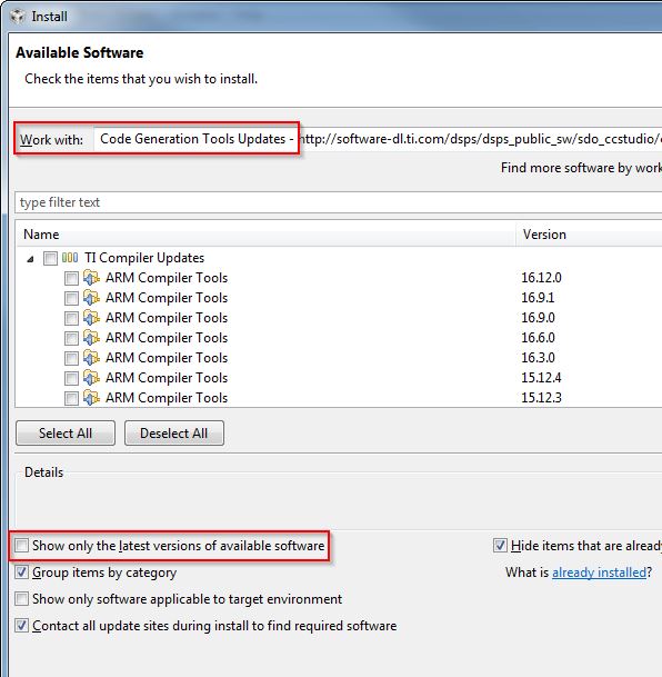
Figure 6. TI ARM Compiler Version in Code Composer Studio
Importing CCS projects
This section describes how to import and build an existing project and references the simple_peripheral project. All of the BLE-Stack 3.00.00 projects included in the development kit have a similar structure.
Note
Before importing a BLE-Stack 3.00.00 project, CCS must discover the Simplelink CC2640R2 SDK. Install the Simplelink CC2640R2 SDK before opening or after restarting CCS.
Open the CCS IDE from the Start Menu.
Create a workspace.
Attention
Ensure that the CCS workspace path does not contain a whitespace.
Import a CCS Project
Select Project -> Import CCS Projects...
Select search directory: <SDK_INSTALL_DIR>\examples\rtos\CC2640R2_LAUNCHXL\blestack\simple_peripheral\tirtos\ccs
CCS discovers several projects, each having a unique build configuration.
- For this example, select simple_peripheral_cc2640r2lp_app and simple_peripheral_cc2640r2lp_stack_library
Select Finish
Caution
Similar as with all other TI projects, CCS needs to discover the Simplelink CC2640R2 SDK before BLE-Stack 3.00.00 projects can be imported.
Click Finish to import (see Figure 7.).
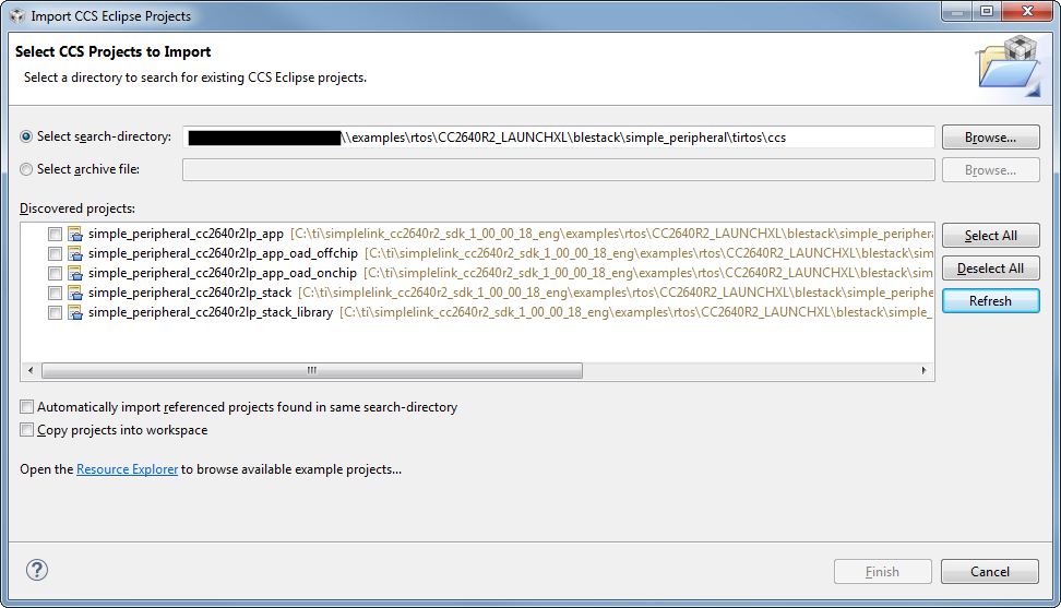
Figure 7. Import CCS Projects
Discovering CCS products
Code Composer Studio automatically discovers the Simplelink CC2640R2 SDK if it installed in its
default installation directory (c:/ti). Once discovered by CCS, it defines a
build enviornment variable named COM_TI_SIMPLELINK_CC2640R2_SDK_INSTALL_DIR
which is used by BLE-Stack 3.00.00 projects.
If a BLE-Stack 3.00.00 project is imported from a path other than what was specificed
during the Simplelink CC2640R2 SDK installation, the COM_TI_SIMPLELINK_CC2640R2_SDK_INSTALL_DIR
variable must be redefined after the import proceeduring at a project-by-project
basis.
To redefine this variable:
Open the CCS project’s properties (Project -> Properties)
Navigate to Resource -> Linked Resources and edit
COM_TI_SIMPLELINK_CC2640R2_SDK_INSTALL_DIRand have it point to your imported root directory location.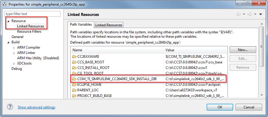
Figure 8. Redefining
COM_TI_SIMPLELINK_CC2640R2_SDK_INSTALL_DIR
BLE-Stack 3.00.00 CCS project build configurations
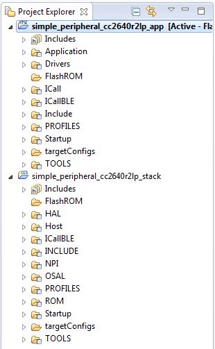
Figure 9. CCS Project Explorer
This and all BLE-Stack 3.00.00 project workspaces contain various projects and build configurations as shown in Table 6. *_StackLibrary build configurations build the stack as a library as described in Stack Library Configuration.
Click the project name in the file explorer to select the project as the active project. In Figure 9., the application is selected as the active project. Each of these projects produces a separate, downloadable image.
The simple_peripheral sample project is the primary sample application for the description of a generic application in this guide. The simple_peripheral project implements a basic Bluetooth low energy peripheral device including a GATT server with GATT services. This project can be used as a framework for developing peripheral-role applications.
| Project type | Project naming convention | Project’s build configuration | Compatible project complement |
|---|---|---|---|
| Application | *_cc2640r2lp_app |
FlashROM | *_cc2640r2lp_stack |
| FlashROM_StackLibrary | *_cc2640r2lp_stack_library |
||
| FlashROM_StackLibrary_RCOSC | *_cc2640r2lp_stack_library |
||
*_cc2640r2lp_app_oad_onchip |
FlashROM_OAD_ImgB | *_cc2640r2lp_stack with FlashROM configuration |
|
*_cc2640r2lp_app_oad_offchip |
FlashROM_OAD_Offchip | *_cc2640r2lp_stack with FlashROM configuration |
|
| Stack | *_cc2640r2lp_stack_library |
FlashROM_Library | *_cc2640r2lp_app with FlashROM_StackLibrary configuration |
*_cc2640r2lp_stack |
FlashROM | *_cc2640r2lp_app with FlashROM configuration |
Compiling and Download
For all build configurations, the stack project should always be built before the application project.
For projects where the stack is built as a library:
Build the stack library project.
- Set the stack project as the active project.
- Select Project -> Build All to build the stack project.
Build the application project.
- Set the application project as the active project.
- Select Project -> Build All to build the application project.
Load the whole application
- Select Run -> Debug to download the application
Note
Application project that consume the stack in a library form will not have hard defined image boundaries.
After the initial build, if the stack project is not modified, only the applicaiton project needs to be rebuilt.
For projects where the stack and application are split images (not a library):
Build the stack project.
- Set the stack project as the active project.
- Select Project -> Build All to build the stack project.
Build the application project.
- Set the application project as the active project.
- Select Project -> Build All to build the application project.
Load the stack project
- Set the stack project as the active project.
- Select Run -> Debug to download the stack
Load the application project
- Set the application project as the active project.
- Select Run -> Debug to download the application
Note
The stack project defines the flash and RAM boundary parameters used by the application project. Any modifications to the stack project require a rebuild of the stack project, followed by a rebuild of the application project to use the new boundary settings. See Frontier Tool Operation.
After the initial build, if the stack project is not modified, only the applicaiton project needs to be rebuilt.
Caution
Do not modify the CPU Variant in the project settings. All sample projects are configured with a CPU type, and changing this setting (that is, from CC2640R2F) may result in build errors.
Sample applications that implement the Over the Air Download (OAD) firmware update capability require the Boot Image Manager (BIM) project to be built. Refer to the Over the Air Download (OAD) section for more details.
Accessing Preprocessor Symbols
Various C preprocessor symbols may need to be set or adjusted at the project level. The following procedure describes how to access and modify preprocessor symbols.
- Open Project Properties
- Navigate to Build -> ARM Compiler -> Predefined Symbols
- Use the buttons highlighted in Figure 10. to add, delete, or edit a preprocessor.
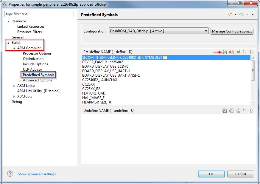
Figure 10. CCS Predefined Symbols
Additional training and support for CCS
For additional training and support with Code Composer Studio, refer to: Code Composer Studio Wiki Code Composer Studio Training
Developing with IAR
Installing IAR
The IAR toolchain contains many features beyond the scope of this document. More information and documentation can be found at IAR.com.
Check the BLE-Stack 3.00.00 release notes to see which IAR version to use and any required workarounds. Object code produced by IAR may differ in size and performance as compared to CCS produced object code.
The following procedure describes installing and configuring the correct version of IAR and the necessary tools.
Install IAR Embedded Workbench for ARM
Download and install IAR EW ARM
To get IAR, choose one of the following methods:
- Download the IAR Embedded Workbench 30-Day Evaluation Edition – This version of IAR is free, has full functionality, and includes all of the standard features. The size-limited Kickstart evaluation option is not compatible with this SDK.
- Purchase the full-featured version of IAR Embedded Workbench – For complete BLE application development using the CC2640R2F, TI recommends purchasing the complete version of IAR without any restrictions. You can find the information on purchasing the complete version of IAR.
Attention
The version required is stated in the release notes. Opening IAR project files with a previous version of IAR may cause project file corruption.
Show Build Messages
TI recommends showing all the build output messages for full verbosity during building. To do this, go to Tools -> Options and set Show Build Messages to All (see Figure 12.)
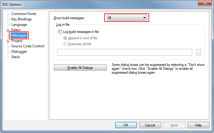
Figure 12. Show All Build Messages in IAR
Opening IAR Projects
This section describes how to open and build an existing project and references the simple_peripheral project. All of the BLE-Stack 3.00.00 projects included in the development kit have a similar structure.
Open the IAR Embedded Workbench IDE from the Start Menu.
Open an IAR workspace project: File -> Open -> Workspace...
- For this example, select <SDK_INSTALL_DIR>\examples\rtos\CC2640R2_LAUNCHXL\blestack\simple_peripheral\tirtos\iar\simple_peripheral.eww
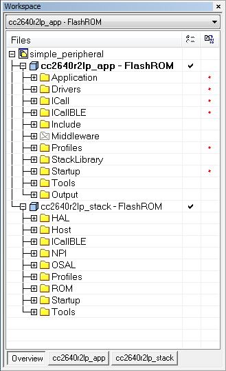
Figure 13. IAR Workspace Pane
This workspace file is for the simple_peripheral project. When selected, the files associated with the workspace become visible in the Workspace pane on the left side of the screen. See Figure 13.
Select either project as the active project by clicking the respective tab at the bottom of the workspace pane. In Figure 13., the Overview tab is selected. This tab displays the file structure for both projects simultaneously. In this case, use the drop-down menu at the top of the workspace pane to select the active project. Each of these projects produces a separate downloadable object. The simple_peripheral sample project is the primary reference target for the description of a generic application in this guide. The simple_peripheral project implements a basic BLE-Stack peripheral device including a GATT server with GATT services. This project can be a framework for developing peripheral-role applications.
BLE-Stack 3.00.00 IAR project build configurations
This and all BLE-Stack 3.00.00 project workspaces contain various projects and build configurations as shown in Table 7. *_StackLibrary build configurations build the stack as a library as described in Stack Library Configuration.
| Project type | Project’s build configuration | Compatible project complement |
|---|---|---|
| Application | FlashROM | Stack - FlashROM |
| FlashROM_StackLibrary | Stack - FlashROM_StackLibrary | |
| FlashROM_StackLibrary_RCOSC | Stack - FlashROM_StackLibrary | |
| FlashROM_OAD_ImgB | Stack - FlashROM | |
| FlashROM_OAD_Offchip | Stack - FlashROM | |
| Stack | FlashROM_Library | Application - FlashROM_Library |
| FlashROM | Application - FlashROM |
Compile and Download
For all build configurations, the stack project should always be built before the application project.
For projects where the stack is built as a library:
Build the stack library project.
- Select the stack project.
- Select Project -> Make to build the stack.
Build the application project.
- Select the application project.
- Select Project -> Make to build the application.
Load the whole application
- To download and debug: Select Project -> Download and Debug
- To download without debugging: Select Project -> Download -> Download Active Application
Note
Application project that consume the stack in a library form will not have hard defined image boundaries.
After the initial build, if the stack project is not modified, only the applicaiton project needs to be rebuilt.
For projects where the stack and application are split images (not a library):
Build the stack project.
- Select the stack project.
- Select Project -> Make to build the stack.
Build the application project.
- Select the application project.
- Select Project -> Make to build the application.
Load the stack project.
- Select Project -> Download -> Download Active Application to download the stack project.
Load the application project.
- To download and debug: Select Project -> Download and Debug
- To download without debugging: Select Project -> Download -> Download Active Application
Note
The stack project defines the flash and RAM boundary parameters used by the application project. Any modifications to the stack project require a rebuild of the stack project, followed by a rebuild of the application project to use the new boundary settings. See Frontier Tool Operation.
After the initial build, if the stack project is not modified, only the applicaiton project needs to be rebuilt.
When the application is downloaded (that is, flash memory programmed), you can debug with reflashing the device. Go to Project -> Debug without Downloading.
Caution
Do not modify the CPU Variant in the project settings. All sample projects are configured with a CPU type, and changing this setting (that is, from CC2640R2F) may result in build errors.
Sample applications that implement the Over the Air Download (OAD) firmware update capability require the Boot Image Manager (BIM) project to be built. Refer to the Over the Air Download (OAD) section for more details.
Accessing Preprocessor Symbols
Various C preprocessor symbols may need to be set or adjusted at the project level. The following procedure describes how to access and modify preprocessor symbols.
- Open the Project’s Options and select the C/C++ Compiler Category.
- Open the Preprocessor tab.
- View the Defined symbols box (see Figure 14.).
- Add or edit the preprocessor symbols.
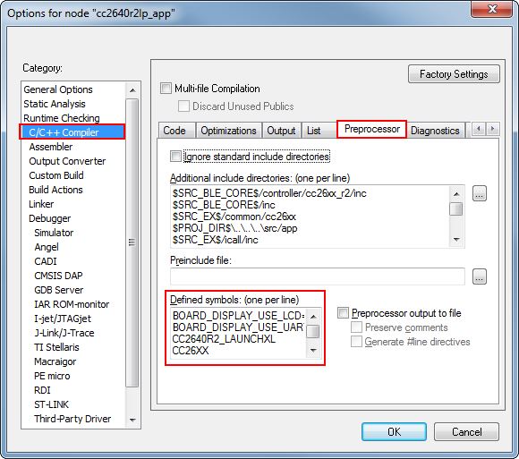
Figure 14. IAR Defined Symbols Box
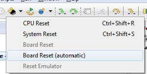
Resetting the CC2640R2F in IAR
Select the Board Reset option from the following Reset (back arrow) Debug Menu drop-down box.
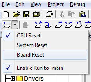
Figure 15. IAR Board Reset
Memory Management
Flash
The flash is split into erasable pages of 4kB. The various sections of flash and their associate linker files are as follows.
- Simple NV (SNV) Area: used for nonvolatile memory storage by the GAP Bond Manager and also available for use by the application. See Using Simple NV for Flash Storage for configuring SNV. When configured, the SNV flash storage area is part of the stack image.
- Customer Configuration Area (CCA): the last sector of flash used to store customer-specific chip configuration (CCFG) parameters. The unused space of the CCA sector is allocated to the application project. See Customer Configuration Area.
For projects where the stack project builds a library:
- Application Image Code Space: used for the application project. This image is configured in the linker configuration file of the application: cc26xx_app.icf (IAR) and cc26xx_app.cmd (CCS).
For split image projects:
- Application Image Code Space: used for the application project. This image is configured in the linker configuration file of the application: cc26xx_app.icf (IAR) and cc26xx_app.cmd (CCS).
- Stack Image Code Space: use for the stack project. This image is configured in the linker configuration file of the stack: cc26xx_stack.icf (IAR) and cc26xx_ stack.cmd (CCS).
Flash Memory Map
This section describes the flash memory map at the system level for split image project configurations. As Figure 16. shows, the application linker file point to symbols with a solid arrow and the stack linker file point to symbols with a dashed arrow.
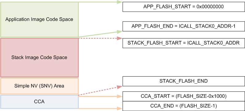
Figure 16. System Flash Map
Note
Projects that include the stack as a library, the Application Image Code Space and Stack Image Code Space are combined in the Application Image Code Space without any boundary requirements associated with split images.
Table 8. summarizes the Flash System Map definitions from Figure 16. and provides the associated linker definitions or symbols that can be found in the respective IDE linker files.
| Symbol/Region | Meaning | Project | CCS Definition | IAR Definition |
| APP_FLASH_START | Start of flash/Start of App code image | App | FLASH_APP_BASE | FLASH_START |
| APP_FLASH_END | End of App code image. (ICALL_STACK0_ADDR-1) | App | ADJ_ICALL_STACK0_START - FLASH_APP_BASE | FLASH_END |
| STACK_FLASH_START | Start of Stack code image (ICALL_STACK0_ADDR) | Stack | FLASH_START | |
| STACK_FLASH_END | End of Stack flash code image, including SNV | Stack | FLASH_SIZE - RESERVED_SIZE | FLASH_END |
| CCA sector | Last sector of flash. Contains the CCFG. | App | FLASH_LAST_PAGE | |
| CCFG region | Location in CCA where Customer Configuration (CCFG) parameters are stored | App | Last 88 bytes (sizeof(ccfg_t) of CCA | |
Application and Stack Flash Boundary
The application and stack code images are based on the common ICALL_STACK0_ADDR and ICALL_STACK0_START predefined symbols. These values define the hardcoded flash address of the entry function for the stack image: it is essentially the a word-aligned flash address of the application-stack project boundary. To ensure proper linking, both the application and stack projects must use the same defined symbols. By default, the linker is configured to allocate unused flash to the application project but can be modified manually or automatically through the frontier tool. For information on using the frontier tool to configure the flash boundary address, see Frontier Tool Operation.
Using Simple NV for Flash Storage
The Simple NV (SNV) area of flash is used for storing persistent data, such as encryption keys from bonding or to store custom defined parameters. The protocol stack can be configured to reserve up to two 4kB flash pages for SNV, although valid data is only stored in one active flash page. To minimize the number of erase cycles on the flash, the SNV manager performs compactions on the flash sector (or sectors) when the sector has 80% invalidated data. A compaction is the copying of valid data to a temporary area followed by an erase of the sector where the data was previously stored. Depending on the OSAL_SNV value as described in OSAL_SNV Values, this valid data is then either placed back in the newly erased sector or remains in a new sector. The number of flash sectors allocated to SNV can be configured by setting the OSAL_SNV preprocessor symbol in the stack project. Table 9. lists the valid values that can be configured as well as the corresponding trade-offs.
| OSAL_SNV Value | Description |
| 0 | SNV is disabled. Storing of bonding keys in NV is not possible. Maximizes code space for the application and/or stack project. GAP Bond Manager must be disabled. In the Stack project, set pre- processor symbol NO_OSAL_SNV and disable GAP Bond Manager. See Stack Configurations for configuring Bluetooth low energy protocol stack features. |
| 1 (default) | One flash sector is allocated to SNV. Bonding info is stored in NV. Flash compaction uses flash cache RAM for intermediate storage, thus a power-loss during compaction results in SNV data loss. Also, due to temporarily disabling the cache, a system performance degradation may occur during the compaction. Set preprocessor symbol OSAL_SNV=1 in the Stack project. |
| 2 | Two flash sectors are allocated to SNV. Bonding information is stored in NV. SNV data is protected against power-loss during compaction. |
Other values for OSAL_SNV are invalid. Using less than the maximum value has the net effect of allocating more code space to the application or stack project. SNV can be read from or written to using the following APIs.
uint8 osal_snv_read( osalSnvId_t id, osalSnvLen_t len, void *pBuf)
| Read data from NV | |
| Parameters | id - valid NV item len - length of data to read pBuf - pointer to buffer to store data read |
| Returns | SUCCESS: NV item read successfully NV_OPER_FAILED: failure reading NV item |
uint8 osal_snv_write( osalSnvId_t id, osalSnvLen_t len, void *pBuf)
| Write data to NV | |
| Parameters | id - valid NV item len - length of data to write pBuf - pointer to buffer containing data to be written. All contents are updated at once. |
| Returns | SUCCESS: NV item write successfully NV_OPER_FAILED: failure writing NV item |
Because SNV is shared with other modules in BLE-Stack 3.00.00 such as the GAP Bond Manager, carefully manage the NV item IDs. By default, the IDs available to the customer are defined in bcomdef.h as shown in Listing 1.
1 2 3 4 5 6 7 8 9 10 11 12 13 14 15 16 17 | // Device NV Items - Range 0 - 0x1F
#define BLE_NVID_IRK 0x02 //!< The Device's IRK
#define BLE_NVID_CSRK 0x03 //!< The Device's CSRK
#define BLE_NVID_SIGNCOUNTER 0x04 //!< The Device's Sign Counter
#define BLE_LRU_BOND_LIST 0x05 //!< The Device's order of bond indexes in least recently used order
// Bonding NV Items - Range 0x20 - 0x5F - This allows for 10 bondings
#define BLE_NVID_GAP_BOND_START 0x20 //!< Start of the GAP Bond Manager's NV IDs
#define BLE_NVID_GAP_BOND_END 0x5f //!< End of the GAP Bond Manager's NV IDs Range
// GATT Configuration NV Items - Range 0x70 - 0x79 - This must match the number of Bonding entries
#define BLE_NVID_GATT_CFG_START 0x70 //!< Start of the GATT Configuration NV IDs
#define BLE_NVID_GATT_CFG_END 0x79 //!< End of the GATT Configuration NV IDs
// Customer NV Items - Range 0x80 - 0x8F - This must match the number of Bonding entries
#define BLE_NVID_CUST_START 0x80 //!< Start of the Customer's NV IDs
#define BLE_NVID_CUST_END 0x8F //!< End of the Customer's NV IDs
|
Listing 2. shows how to read and write an array of bytes from SNV flash:
/*********************************************************************
* GLOBAL VARIABLES
*/
#define BUF_LEN 4
#define SNV_ID_APP 0x80
uint8 buf[BUF_LEN] ={0,};

static void SimpleBLEPeripheral_taskFxn(UArg a0, UArg a1)
{
  // Initialize application
  SimpleBLEPeripheral_init();
  uint8 status = SUCCESS;

  status = osal_snv_read(SNV_ID_APP, BUF_LEN, (uint8 *)buf);
  if(status != SUCCESS)
  {
    Display_print1(dispHandle, 0, 0, "SNV READ FAIL: %d", status);
    //Write first time to initialize SNV ID
    osal_snv_write(SNV_ID_APP, BUF_LEN, (uint8 *)buf);
  }

  //Increment first element of array and write to SNV flash
  buf[0]++;
  status = osal_snv_write(SNV_ID_APP, BUF_LEN, (uint8 *)buf);
  if(status != SUCCESS)
  {
    Display_print1(dispHandle, 0, 0, "SNV WRITE FAIL: %d", status);
  }
  else
  {
    Display_print1(dispHandle, 0, 0, "Num of Resets: %d", buf[0]);
  }

  // Application main loop
  for (;;)
  {
  ...
No prior initialization of a NV item ID is required; the OSAL SNV manager initializes the NV ID when first accessed by a successful osal_snv_write() call.
When reading or writing large amounts of data to SNV, TI recommends placing the read/write data in statically (linker) allocated arrays or buffers allocated from the heap. Placing large amounts of data in local arrays may result in a task stack overflow.
By default, osalSnvId_t and osalSnvLen_t are type defined as uint8. To use uint16-type definitions, define the preprocessor symbol OSAL_SNV_UINT16_ID in both the application and stack projects.
Using osal_snv_read and osal_snv_write is only permitted from within a task context. Calling this API is not possible from within Swi’s or Hwi’s.
Customer Configuration Area
The Customer Configuration Area (CCA) occupies the last page of flash and lets a customer configure various chip and system parameters in the Customer Configuration (CCFG) table . The CCFG table is defined in ccfg_app_ble.c, which can be found in the Startup folder of the application project. The last 88 (sizeof(ccfg_t)) bytes of the CCA sector are reserved by the system for the CCFG table. By default, the linker allocates the unused flash of the CCA sector to the application image for code and data use. The linker can be modified to reserve the entire sector for customer parameter data (for example, board serial number and other identity parameters).
The CCA region is defined linker file of the application by the FLASH_LAST_PAGE symbol. Placement is based on the IDE:
For CCS:
MEMORY
{
    ...
    // CCFG Page, contains .ccfg code section and some application code.
    FLASH_LAST_PAGE (RX) :  origin = FLASH_LAST_PAGE_START, length = FLASH_PAGE_LEN
    ...
}

SECTIONS
{
    ...
    .ccfg           :   >  FLASH_LAST_PAGE (HIGH)
    ...
}
For IAR:
////////////////////////////////////////////////////////////////////////////////
// Memory Regions
////////////////////////////////////////////////////////////////////////////////
...
define region FLASH_LAST_PAGE       = mem:[from(FLASH_SIZE - PAGE_SIZE) to FLASH_SIZE-1];
...
////////////////////////////////////////////////////////////////////////////////
...
// CCFG
place at end of FLASH_LAST_PAGE { readonly section .ccfg };
keep { section .ccfg }
See the CC26xx Technical Reference Manual for details on CCFG fields and related configuration options, including how to set the CCFG to disable access to internal flash memory contents.
RAM
Similar to flash, the RAM is shared between the application and stack projects. The RAM sections are configured in their respective linker files.
- Application Image: RAM space for the application and shared heaps. This image is configured in the linker configuration file of the application: cc26xx_app.icf (IAR) and cc26xx_app.cmd (CCS).
- Stack Image: RAM space for the .bss and .data sections of the stack. This image is configured in the linker configuration file of the stack: cc26xx_stack.icf (IAR) and cc26xx_stack.cmd (CCS).
RAM Memory Map
System Memory Map shows the system memory map for the default simple_peripheral project. This is a summary and the exact memory placement for a given compilation can be found in the simple_peripheral_app.map and simple_peripheral_stack.map files in the output folder in IAR or the FlashROM folder in CCS. In Check System Flash and RAM Usage With Map File, the application linker file contains symbols pointed with a solid arrow and the stack linker file contains symbols pointed with a dashed arrow.
System Memory Map
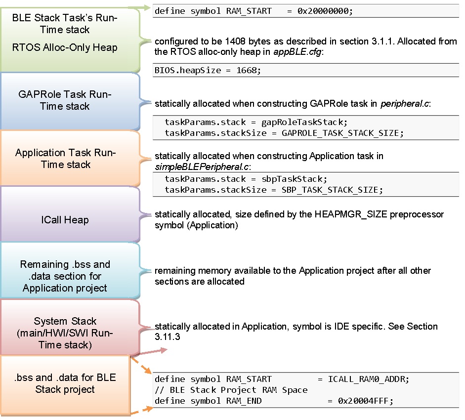
Figure 17. System Memory Map
Application and Stack RAM Boundary
The application and stack RAM memory maps are based on the common ICALL_RAM0_START defined symbol. This value defines the hardcoded RAM boundary for the end of the RAM space of the application and the start of the image of the stack .BSS and .DATA sections. Unlike the flash boundary, elements of the stack project (such as task stacks and heaps) are allocated in the application project. To ensure proper linking, both the application and stack projects must use the same ICALL_RAM0_START value. By default, ICALL_RAM0_START is configured to allocate unused RAM to the application project through the frontier tool. For information on using the frontier tool to configure the RAM boundary address, see Frontier Tool Operation.
System Stack
Besides the RTOS and ICall heaps, consider other sections of memory. As described in Tasks, each task has its own runtime stack for context switching. Another runtime stack is used by the RTOS for main(), HWIs, and SWIs. This system stack is allocated in the application linker file to be placed at the end of the RAM of the application.
For IAR, this RTOS system stack is defined by the CSTACK symbol:
////////////////////////////////////////////////////////////////////////////////
// Stack
define symbol STACK_SIZE            = 0x400;
define symbol STACK_START           = RAM_END + 1;
define symbol STACK_END             = STACK_START - STACK_SIZE;
//
define symbol STACK_TOP             = RAM_END + 1;
export symbol STACK_TOP;

// Runtime Stack
define block CSTACK with alignment = 8, size = STACK_SIZE { section .stack };
place at end of RAM { block CSTACK };
In IAR, to change the size of the CSTACK, adjust the STACK_SIZE symbol value in the linker file of the application.
For CCS, the RTOS system stack is defined by the Program.stack parameter in the appBLE.cfg RTOS configuration file:
/* main() and Hwi, Swi stack size */
Program.stack = 1024;
and placed by the linker in the RAM space of the application:
/* Create global constant that points to top of stack */
/* CCS: Change stack size under Project Properties */
__STACK_TOP = __stack + __STACK_SIZE;
Dynamic Memory Allocation
The system uses two heaps for dynamic memory allocation. The application designer must understand the use of each heap to maximize the use of available memory.
The RTOS is configured with a small heap in the app_ble.cfg RTOS configuration file:
var HeapMem = xdc.useModule('xdc.runtime.HeapMem');

BIOS.heapSize = 1668;
This heap (HeapMem) is used to initialize RTOS objects and allocate the task runtime stack of the Bluetooth low energy protocol stack. TI chose this size of this heap to meet the system initialization requirements. Due to the small size of this heap, TI does not recommend allocating memory from the RTOS heap for general application use. For more information on the TI-RTOS heap configuration, see the Heap Implementations section of the TI-RTOS SYS/BIOS Kernel User’s Guide.
The application must use a separate heap. The ICall module uses an area of application RAM which can be used by the various tasks. The size of this ICall heap is defined by the HEAPMGR_SIZE preprocessor definition in the application project. Using a non-zero value sets the ICall heap to the specified value, while a HEAPMGR_SIZE value of zero (0) auto sizes the heap to a size equal to the amount of available free RAM not allocated by the linker. By default, the simple_peripheral project uses the auto size feature. Although the ICall heap is defined in the application project, this heap is also shared with the Bluetooth low energy protocol stack. APIs that allocate memory (such as GATT_bm_alloc()) allocate memory from the ICall heap.
To profile the amount of ICall heap used, define the HEAPMGR_METRICS preprocessor symbol in the application project. Refer to Profiling the ICall Heap Manager (heapmgr.h) to determine the size of the ICall heap when the auto heap size feature is enabled.
Note
The auto heap size feature does not determine the amount of heap needed for the application. The system designer must ensure that the heap has the required space to meet the application’s runtime memory requirements.
The following is an example of dynamically allocating a variable length (n) array using the ICall heap:
//define pointer
uint8_t *pArray;
// Create dynamic pointer to array.
if (pArray = (uint8_t*)ICall_malloc(n*sizeof(uint8_t)))
{
//fill up array
}
else
{
//not able to allocate
}
The following is an example of freeing the previous array:
ICall_free(pMsg->payload);
Frontier Tool
The frontier tool is a utility to automatically adjust the respective RAM and flash boundary address symbols shared between the application and stack projects built as split images. Project where the application consumes the stack as a library do not require the use of the Frontier Tool.
Frontier runs as a post-build step of the stack project, and adjusts the respective RAM and flash boundaries based on analysis of the stack linker and map files. No project files are modified by the frontier tool. The frontier tool does not modify any source code or perform any compiler or linker optimization; the tool adjusts and updates the respective flash and RAM boundary addresses, located in the compiler and linker configuration files used by the application and stack projects.
The frontier tool is installed to the following path within the SDK: <SDK_INSTALL_DIR>\examples\rtos\CC2640R2_LAUNCHXL\blestack\tools\frontier\frontier.exe
The python source for this tool is also included.
Table 10. shows the boundary address symbols updated by the frontier tool.
| Boundary Address Symbol | Definition |
|---|---|
| ICALL_STACK0_START | Boundary flash address between application and stack images. Represents the end of the application image and the beginning of the stack image. |
| ICALL_STACK0_ADDR | Stack entry address (flash) |
| ICALL_RAM0_START | Boundary RAM address between application and stack images. Represents the end of the application RAM and the beginning of the stack RAM. |
All sample application projects are, by default, configured to use the frontier tool; thus, no user configuration of the frontier tool is required. The boundary files may be updated when the stack configuration is changed, or when any files are updated in the stack project that result in a change in the size of the stack image. It is therefore required to rebuild the application project anytime the stack project is built.
Note
The frontier tool replaces the boundary tool used in earlier SDKs.
Frontier Tool Operation
The frontier tool (frontier.exe) is invoked as a CCS or IAR IDE post-build operation of the stack project. If an adjustment to the RAM or flash boundary is required, the frontier tool updates the boundary linker configuration and C definition files listed below. To incorporate the updated configuration values, perform a Project -> Rebuild All on the application project. The stack project must build and link correctly before the application can be rebuilt.
Each project in the SDK has a set of configuration files that the linker and compiler of the IDE use to set or adjust the respective flash and RAM values. These configuration files are shared between the application and stack workspaces, and are stored at the following location:
<SDK_INSTALL_DIR>\examples\rtos\<EVAL_BOARD>\blestack\<PROJECT>\tirtos\<IDE>\config
Where <EVAL_BOARD> is the evaluation platform, <PROJECT> is the sample application (for example, simple_peripheral), and <IDE> is either IAR or CCS.
For example, the simple_peripheral sample application running on the CC2640R2F LaunchPad, the boundary config files are located at the following paths:
CCS: <SDK_INSTALL_DIR>\examples\rtos\CC2640R2_LAUNCHXL\blestack\simple_peripheral\tirtos\ccs\config
IAR: <SDK_INSTALL_DIR>\examples\rtos\CC2640R2_LAUNCHXL\blestack\simple_peripheral\tirtos\iar\config
The following are the boundary config files:
- Boundary linker configuration file: iar_boundary.xcl [IAR] or ccs_linker_defines.cmd [CCS]. Defines the boundary addresses for the linker. This file is in the TOOLS IDE folder and is updated by the frontier tool when an adjustment is required.
- Boundary C definition file: iar_boundary.bdef [IAR] or ccs_compiler_defines.bcfg [CCS]. Defines the boundary addresses for the compiler. This file is in the TOOLS IDE folder and is updated by the frontier tool when an adjustment is required.
Note
The values in the boundary linker configuration file and the boundary C definition file must match.