|
MCUSW
|
|
MCUSW
|
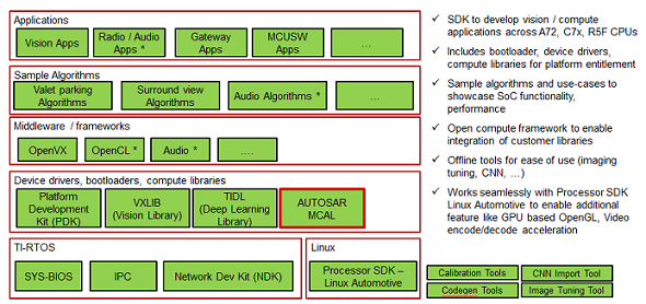
SoC's such as J721E/J7200/J721S2/J784S4/AM62x/AM62A, integrates an MicroController Unit Subsystem (MCU SS) as an chip-in-chip. It operates using a separate voltage supply, clock sources and resets and includes the components needed for device management. This allows the MCUSS to function continuously regardless of the state of the rest of the device. MCU SS has one or more DUAL core Cortex R5F (number of instances varies on the variant of the device, please refer the device reference manual)
MCUSW consists of two main components, Microcontroller abstraction layer (MCAL) & Demonstration applications (MCUSS Demos). Its is expected to be hosted on Cortex R5F 0 in MCU Domain or other Cortex R5F in main domain. The table below lists SoC/Cores on which MCUSW can be hosted.
| Device Family | Also known by other names |
|---|---|
| J721E | AM752X, DRA829, TDA4VM, J7ES |
| J7200 | DRA821, J7VCL |
| J721S2 | DRA820, TDA4VL, J7AEP |
| J784S4 | TDA4VH, TDA4AH, J7AHP |
| AM62Ax | - |
| AM62x | - |
| AM62P | - |
| SoC Family | Cores Names | Referred as | Comments |
|---|---|---|---|
| J721E | MCU R5F Core 0 | mcu 1 0 | Please refer the "mcusw_release_notes.html" to determine if this release supports this platform. Note that all computing cores might not be supported in MCUSW |
| MCU R5F Core 1 | mcu 1 1 | ||
| 1ST MCU Core 0 | mcu 2 0 | ||
| 1ST MCU Core 1 | mcu 2 1 | ||
| 2ND MCU Core 0 | mcu 3 0 | ||
| 2ND MCU Core 1 | mcu 3 1 | ||
| A72 Core 0 | mpu 1 0 | ||
| A72 Core 1 | mpu 1 1 | ||
| 1ST C66X DSP | c66x_1 | ||
| 2ND C66X DSP | c66x_2 | ||
| C7X DSP | c7x_1 | ||
| J7200 | MCU R5F Core 0 | mcu 1 0 | Please refer the "mcusw_release_notes.html" to determine if this release supports this platform. Note that all computing cores might not be supported in MCUSW |
| MCU R5F Core 1 | mcu 1 1 | ||
| 1ST MCU Core 0 | mcu 2 0 | ||
| 1ST MCU Core 1 | mcu 2 1 | ||
| A72 Core 0 | mpu 1 0 | ||
| A72 Core 1 | mpu 1 1 | ||
| J721S2 | MCU R5F Core 0 | mcu 1 0 | Please refer the "mcusw_release_notes.html" to determine if this release supports this platform. Note that all computing cores might not be supported in MCUSW |
| MCU R5F Core 1 | mcu 1 1 | ||
| 1ST MCU Core 0 | mcu 2 0 | ||
| 1ST MCU Core 1 | mcu 2 1 | ||
| A72 Core 0 | mpu 1 0 | ||
| A72 Core 1 | mpu 1 1 | ||
| J784S4 | MCU R5F Core 0 | mcu 1 0 | Please refer the "mcusw_release_notes.html" to determine if this release supports this platform. Note that all computing cores might not be supported in MCUSW |
| MCU R5F Core 1 | mcu 1 1 | ||
| 1ST MCU Core 0 | mcu 2 0 | ||
| 1ST MCU Core 1 | mcu 2 1 | ||
| A72 Core 0 | mpu 1 0 | ||
| A72 Core 1 | mpu 1 1 | ||
| AM62AX/AM62P | MCU R5F Core 0 | mcu 0 0 | Please refer the "mcusw_release_notes.html" to determine if this release supports this platform. Note that all computing cores might not be supported in MCUSW |
| AM62X | DM R5F Core 0 | mcu 0 0 | Please refer the "mcusw_release_notes.html" to determine if this release supports this platform. Note that all computing cores might not be supported in MCUSW |
Demonstrates usage of various drivers / software provided for MCU SS. These applications could employ FREERTOS as OS and use MCAL and/or PDK drivers. Please note, these demos are currently not supported on Sitara MPU Family of Devices.
(TI RTOS support has now been removed, and all demos will be using only FREERTOS.)
Listed below are application supported, demo specific pages list the supported SoC/Cores
| Demo | Comments | Refer | J721E | J7200 | J721S2 | J784S4 |
|---|---|---|---|---|---|---|
| Can Profiling | Application to determine the CPU load for transmission & reception of CAN messages | (CAN Profiling Application) | Yes | Yes | Yes | Yes |
| CDD IPC Profiling | Application to determine the time required for transmission & reception of messages of various sizes | (CDD IPC Profiling Application) | Yes | Yes | No | No |
| Execute In Place (XIP) - Can Response Demo | Application demonstrates operating MCU Domain R5F (MCU 1 0) in XIP mode | (Execute In Place (XIP) Application) | Yes | Yes | No | No |
| Multi-Core Boot Application | Application demonstrates Booting of all cores from MCU R5F (MCU 1 0) while simultaneously sending out CAN messages | (CAN Response Application) | Yes | Yes | No | No |
| Mode Switch Application | This application demonstrates steps to switch mode from ACTIVE (full SoC powered ON) to MCU Only mode and then from MCU Only to ACTIVE mode on J721E EVM. | (Mode Switch Application) | Yes | No | No | No |
| XIP FOTA | This application demonstrates execute-in-place, where in CAN Profiling Application is executed from OSPI memory. | (Execute In Place (XIP) + Firmware Over The Air (FOTA) Application) | Yes | Yes | Yes | Yes |
MCAL is the lowest layer of the AUTOSAR Basic Software architecture. MCAL contains drivers with direct access to the μC internal peripherals. MCAL is a hardware specific layer that ensures a standard interface to the Basic Software.
This user guide details procedure that are common to all MCAL drivers, please refer driver specific user guide for finer details of driver.
For Jacinto Family of Devices:
| Driver | Comments | Refer | Supported SoC | Supported Cores |
|---|---|---|---|---|
| Adc | Driver for built-in Adc peripheral | (Adc User Guide) | J721E | MCU 1 0, MCU 2 1, MCU 2 0*, MCU 3 0* |
| J7200 | MCU 1 0, MCU 2 1 | |||
| J721S2 | MCU 1 0, MCU 2 1 | |||
| J784S4 | MCU 1 0, MCU 2 1 | |||
| Can | Driver for built-in CAN peripheral | (Can User Guide) | J721E | MCU 1 0, MCU 2 1, MCU 2 0*, MCU 3 0* |
| J7200 | MCU 1 0, MCU 2 1 | |||
| J721S2 | MCU 1 0, MCU 2 1 | |||
| J784S4 | MCU 1 0, MCU 2 1 | |||
| AM62x/62Ax/62P | MCU 0 0 | |||
| Cdd Ipc | Driver for inter-processor communication | (Cdd Ipc User Guide) | J721E | MCU 2 1, MCU 2 0*, MCU 3 0* |
| J7200 | MCU 2 1 | |||
| J721S2 | MCU 1 0, MCU 2 1 | |||
| J784S4 | MCU 1 0, MCU 2 1 | |||
| AM62x/62Ax/62P | MCU 0 0 | |||
| Eth | Driver for built in CPSW 2G port | (Eth & EthTrcv User Guide) | J721E | MCU 1 0 |
| J7200 | MCU 1 0 | |||
| J721S2 | MCU 1 0 | |||
| AM62x/62Ax/62P | MCU 0 0 | |||
| Eth Virt Mac | Driver for external Flash Device | (Eth & EthTrcv User Guide) | J721E | MCU 2 1 |
| J7200 | MCU 2 1 | |||
| J721S2 | MCU 2 1 | |||
| EthTrcv | Driver for Ethernet Transceiver and tested with DP83867 | (Eth & EthTrcv User Guide) | J721E | MCU 1 0 |
| J7200 | MCU 1 0 | |||
| J721S2 | MCU 1 0 | |||
| AM62x/62Ax/62P | MCU 0 0 | |||
| Fls | Driver for external Flash Device | (Fls User Guide) | J721E | MCU 1 0, MCU 2 1 |
| J7200 | MCU 1 0, MCU 2 1 | |||
| J721S2 | MCU 1 0, MCU 2 1 | |||
| J784S4 | MCU 1 0, MCU 2 1 | |||
| AM62x/62Ax/62P | MCU 0 0 | |||
| Gpt | Driver for General purpose timer | (Gpt User Guide) | J721E | MCU 1 0, MCU 2 1, MCU 2 0*, MCU 3 0* |
| J7200 | MCU 1 0, MCU 2 1 | |||
| J721S2 | MCU 1 0, MCU 2 1 | |||
| J784S4 | MCU 1 0, MCU 2 1 | |||
| AM62x/62Ax/62P | MCU 0 0 | |||
| Pwm | Driver for Pulse-width-Modulation, uses built-in General purpose timer | (Pwm User Guide) | J721E | MCU 1 0, MCU 2 1, MCU 2 0*, MCU 3 0* |
| J7200 | MCU 1 0, MCU 2 1 | |||
| J721S2 | MCU 1 0, MCU 2 1 | |||
| J784S4 | MCU 1 0, MCU 2 1 | |||
| Pwm | Driver for Pulse-width-Modulation, uses built-in enhanced PWM(ehrPwm) | (Pwm User Guide) | J721E | MCU 1 0, MCU 2 1, MCU 2 0*, MCU 3 0* |
| J7200 | MCU 1 0, MCU 2 1 | |||
| J721S2 | MCU 1 0, MCU 2 1 | |||
| J784S4 | MCU 1 0, MCU 2 1 | |||
| Spi | Handler and driver for Serial Peripheral Interface | (Spi User Guide) | J721E | MCU 1 0, MCU 2 1, MCU 2 0*, MCU 3 0* |
| J7200 | MCU 1 0, MCU 2 1 | |||
| J721S2 | MCU 1 0, MCU 2 1 | |||
| J784S4 | MCU 1 0, MCU 2 1 | |||
| AM62x/62Ax/62P | MCU 0 0 | |||
| Dio | Driver for control of GPIO | (Dio User Guide) | J721E | MCU 1 0, MCU 2 1, MCU 2 0*, MCU 3 0* |
| J7200 | MCU 1 0, MCU 2 1 | |||
| J721S2 | MCU 1 0, MCU 2 1 |
^ |^ |^ | J784S4 | MCU 1 0, MCU 2 1^ |^ |^ | AM62x/62Ax/62P | MCU 0 0 ^ |^ |^ | AM62x/62Ax/62P | MCU 0 0 Wdg | Driver for built in WWDT(Windowed Watchdog Timer) | (Wdg User Guide) | J721E | MCU 1 0, MCU 2 1, MCU 2 0*, MCU 3 0* ^ |^ |^ | J7200 | MCU 1 0, MCU 2 1 ^ |^ |^ | J721S2 | MCU 1 0, MCU 2 1 ^ |^ |^ | J784S4 | MCU 1 0, MCU 2 1 ^ |^ |^ | AM62x/62Ax/62P | MCU 0 0 Icu | Driver for built in ICU (ECAP hardware) | (Icu User Guide) | J721E | MCU 1 0, MCU 2 1 ^ |^ |^ | J7200 | MCU 1 0, MCU 2 1 ^ |^ |^ | J721S2 | MCU 1 0, MCU 2 1 ^ |^ |^ | J784S4 | MCU 1 0, MCU 2 1 Mcu | Driver for built in MCU (CLOCK hardware) | (Mcu User Guide) | J721E | MCU 1 0, MCU 2 1 ^ |^ |^ | J7200 | MCU 1 0, MCU 2 1 ^ |^ |^ | J721S2 | MCU 1 0, MCU 2 1 ^ |^ |^ | J784S4 | MCU 1 0, MCU 2 1 ^ |^ |^ | AM62x/62Ax/62P | MCU 0 0
Dependencies can be categorized as listed below. Please note that depending on the intended use, the dependencies vary (e.g. for integration vs running demo applications only)
Please refer to the Jacinto and Sitara MPU Device SDK User Guides for Hardware Boot Mode details.
Jacinto and Sitara MPU Device EVMs includes an on-board XDS110 USB emulator, which could be used with CCS. Please refer to ti.com or contact your FAE for documents describing the EVM.
An external emulator such as Spectrum Digital XDS560V2 could be used, all steps remain identical to steps listed in (Built in emulator) with creation of Target Configuration being the exception.
While creating the target, please select the emulator that is being used.
MCUSW is delivered as part of SDK. All SW dependencies will be part of the SDK packaging. Please refe to release notes per release for updated information on supported Compilers.
"PDK" is a component within PSDKRA. Following section list the sub-components of PDK that are used / required by MCAL modules.
Please check release note that came with this release for the compatible version of PDK/SDK
UDMA is used to move data between peripherals and memory.
The table below lists each module dependencies on PDK components
| MCAL | CSL | UDMA PDK Library | SCIClient (Only MCAL Examples) | IPC Baremetal |
|---|---|---|---|---|
| Adc | NO | NO | YES | NO |
| Can | NO | NO | YES | NO |
| CddIpc | NO | NO | YES | NO |
| Dio | NO | NO | YES | NO |
| Eth | NO | NO | YES | YES |
| Fls | NO | NO | YES | NO |
| Gpt | NO | NO | YES | NO |
| Pwm | NO | NO | YES | NO |
| Spi | NO | YES | YES | NO |
| Wdg | NO | NO | YES | NO |
| Icu | NO | NO | YES | NO |
| Mcu | NO | NO | YES | NO |
Please refe to release notes per release for updated information on supported Compilers.
Get required MCU Plus SDK release version from below locations, and place it in same location as mcusw folder.:
Elektrobit Tresos (EB) is used to configure the MCAL modules, please refer (MCAL Configurator User Guide) for details.
This tool would be required to re configure the MCAL modules provided by TI.
Code Composer Studio is an integrated development environment (IDE) that supports TI's Microcontroller and Embedded Processors portfolio.
Please refer to Release Notes to find the supported CCS Version. Please refer to SDK User Guides for CCS Setup instructions.
MCUSW is a part of PSDKRA JACINTO and could be installed from that installer. No additional steps required. However, the MCAL configurator would require an additional step. Please refer (Getting access to MCUSW) to receive installer for configurator and steps to obtain licese is detailed in (License for Configurator)
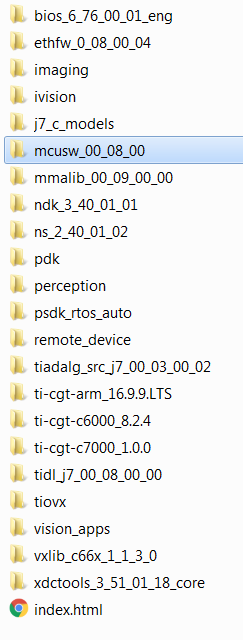
Please note that this is an indicative image, actual versions would change
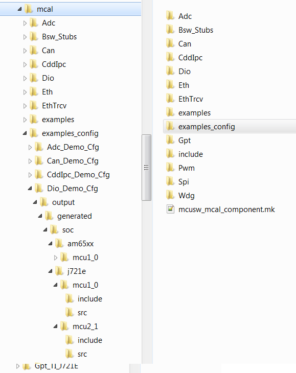
Post installation of MCUSW, the following directory would be created. Please note that this is an indicative snap-shot. Modules/Drivers could be added/modified.
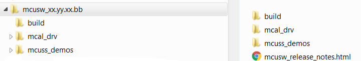
MCAL Directory structure, contains MCAL modules, build files. Please note that this is an indicative snap-shot. Modules/Drivers could be added/modified.
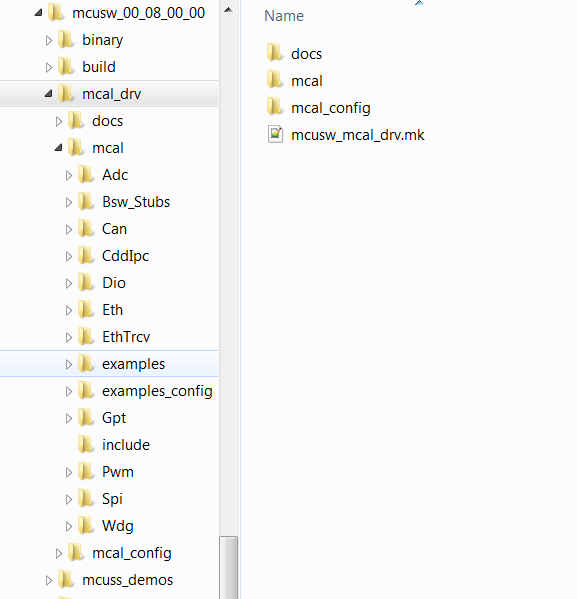
Contains demo applications that demonstrate use of MCAL modules. An integrator could refer these to determine the dependencies of the module.
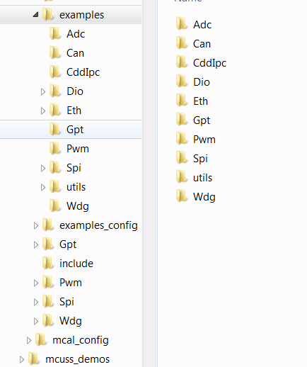
Contains configurations (standalone i.e. configuration for given module and its dependencies, such as Gpt (not dependent on other modules), Can (with Dio, etc...))
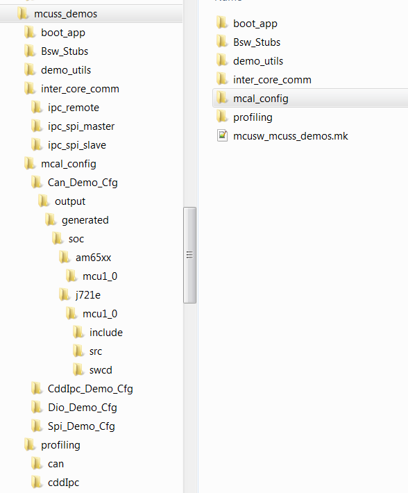
Please refer (MCU Demos) for more information on supported demo applications
MCAL employs make based build mechanism. When building on Windows based machine, tool such as Cygwin could be used.
Following changes are required to be performed in Rules.make to build
If PSDKRA Jacinto is installed sucessfully, no specific changes are required to build. Please refer to Steps to build in windows to build MCAL examples.
To build for J7200, ensure using BOARD=j7200_evm and SOC=j7200 explicitly in each command. By default J721E is selected.
Example: gmake -s all BOARD=j7200_evm SOC=aj7200
With steps listed at (Setup Build Environment) all MCAL modules can be built
With steps listed at (Setup Build Environment) completed MCAL modules can be built
The example applications use different memory and this could be changed/re-configured.

This section below is applicable to SoC's that include one or more R5F CPU in main domain. By default the MCAL library could be built for all R5F cores in main domain. However, the example application will require to be ported. The table (Supported Drivers) lists examples that are supported in this release. One can refer the existing application supported on R5F (MCU 10 or MCU 21) as reference for updating the example. Please note that mcu2_0 core used below is just for demonstration purpose.
Please refer (IDE (CCS)) for CCS and GEL setup
To build the SBL binary for SD/MMC, please use the following command:
$cd ($PSDKRA_INSTALL_PATH)/pdk_jacinto_07_xx_xx/packages/ti/build
J721E : $make sbl_mmcsd_img BOARD=j721e_evm SOC=j721e
J7200 : $make sbl_mmcsd_img BOARD=j7200_evm SOC=j7200
Post compilation of SBL, the SBL binary can be found at ($PSDKRA_INSTALL_PATH)/(pdk-install-folder)/packages/ti/boot/sbl/binary/(SOC)_evm/(boot-media)/bin/*.tiimage
To bo able to boot from SD card copy the following to the SD card boot partition (FAT32)
Steps below highlight the steps required to programe OSPI with binary image
1-OFF, 2-ON, 3-ON, 4-ON, 5-OFF, 6-OFF, 7-ON, 8-OFF, 9-ON, 10-OFF
SW8: 1-OFF, 2-OFF, 3-OFF, 4-OFF, 5-OFF, 6-OFF, 7-OFF, 8-OFF
SW9: 1-OFF, 2-ON, 3-ON, 4-ON, 5-OFF, 6-OFF, 7-OFF, 8-OFF
Eg: dslite.bat --mode processors -c COM55 -f C:\ti\uniflash_6.1.0\processors\FlashWriter\j721e_evm\uart_j721e_evm_flash_programmer_release.tiimage -i 0
Eg: dslite.bat --mode processors -c COM55 -f C:\ti\j7_evm_repo\pdk\packages\ti\boot\sbl\binary\j721e_evm\ospi\bin\sbl_ospi_img_mcu1_0_release.tiimage -d 3 -o 0
Eg: dslite.bat --mode processors -c COM55 -f C:\ti\j7_evm_repo\pdk\packages\ti\drv\sciclient\soc\V1\tifs.bin -d 3 -o 80000
Eg: dslite.bat --mode processors -c COM55 -f C:\ti\j7_evm_repo\pdk\packages\ti\binary\udma_memcpy_testapp\bin\j721e_evm\udma_memcpy_testapp_mcu1_0_release.appimage -d 3 -o 100000
Eg: dslite.bat --mode processors -c COM55 -f C:\ti\j7_evm_repo\pdk\packages\ti\board\src\flash\nor\ospi\nor_spi_patterns.bin -d 3 -o 3FE0000
Note : In Windows, during flashing if you get any error "Unknown response from the target", please disconnect and reconnect micro USB cable and then try to flash again. Note : For J7200 platform, during flashing please select from uniflash_6.1.0/processors/FlashWriter/j7200_evm/uart_j7200_evm_flash_programmer_release.tiimage.
| Mode | Switch Settings |
|---|---|
| UART | SW8: 0000_0000, SW9: 0111_0000 |
| OSPI (J721E) | SW8: 0000_0000, SW9: 0100_0000 |
| OSPI (J7200) | SW8: 1000_0010, SW9: 0011_0000 |
| OSPI (J721S2) | SW8: 0000_1010, SW9: 0110_0000 |
| OSPI (J784S4) | SW11: 0000_1010, SW7: 0110_0000 |
| Flag | Description |
|---|---|
| -g | Default behavior. Enables symbolic debugging. The generation of debug information do not impact optimizations. Therefore, generating debug information is enabled by default. |
| -c | Disables linking |
| Super Quite Mode | |
| -pdsw225 | Categorizes the diagnostic identified by num as a warning |
| -march | direct the compiler to target a particular architecture |
| –endian=little | Little Endian |
| -Wall | Enable most warning categories |
| -Wno | Disable the specified warning category. |
| -mv7R5 | Processor Architecture Cortex-R5 |
| -mcpu | Select the target processor version. |
| -mfpu | option to specify which floating-point hardware is available for use by the compiler |
| -mfloat-abi | option in combination with the appropriate -mfpu option depending on what Arm processor variant is in use. |
| –abi=eabi | Application binary interface - ELF |
| -eo.oem4 | Output Object file extension |
| -ea.sem4 | Output assembly file extension |
| –symdebug:dwarf | Generate symbolic debug in DWARF format |
| –embed_inline_assembly | Embed inline assembly in code for optimization |
| –float_support=vfplib | VFP coprocessor is enabled |
| –emit_warnings_as_errors | Treat warning as errors |
| -os | Interlists optimizer comments with assembly statements |
| –optimize_with_debug | Optimize fully in the presence of debug |
| -DBUILD_MCU1_0, -DBUILD_MCU2_0, -DBUILD_MCU1_1, -DBUILD_MCU2_1 | Identifies Core in the domain |
| -DBUILD_MCU | Identifies Domain |
| -Xlinker | Required by TI Arm Clang |
| –diag_suppress | Suppresses the diagnostic identified by num. |
| –ram_model | option tells the linker to initialize variables at load time |
| –reread_libs | option, you can force the linker to reread all libraries |
| -DSOC_J721E, -DSOC_J7200, -DSOC_J721S2, -DSOC_J784S4 | Device Identifier |
| Please note that all MCAL modules do not support this version. Please refer the release notes for details | |
| Please note that both flags (-DAUTOSAR_421 & -DAUTOSAR_431) cannont be used simultaneously | |
| These flags will be deprecated once all MCAL modules migrate to AUTOSAR Specificaion v4.3.1 |
*Note – is actually 2 "-" dashes they simply appear as one long dash in the user Guide.
Same flags that were used for driver (MCAL Drivers - Profile : Release), additional flags listed below
By default CORE SDK RTOS JACINTO support to be built in Linux environment. All the required tools (compilers, OS, etc...) are packaged in CORE SDK RTOS, which enables MCUSW to built without any modifications.
The components MCUSW and PDK can be built in windows environment, with right version of tools.
List below details the steps required to build MCAL (MCUSW) examples in windows environment
| Core | Examples Not Supported | Comments |
|---|---|---|
| MCU 1 0 | Multi-Core Boot Application | As demo reuqires Linux/QNX, C7x & C66 apps |
| MPU 1 0 | IPC Remote Client Application | Not Yet supported |
| MCU 1 0 | can_profile_xip_app | Creation of .bin image is not supported |
| MCU 1 0 | fls_xip | Creation of .bin image is not supported |
| Revision | Date | Author | Description |
|---|---|---|---|
| 0.1 | 24 Sep 2018 | Sujith S | Created for V 00 03 00 |
| 0.2 | 22 Oct 2018 | Sujith S | Added SBL steps and addressed review comments |
| 0.3 | 24 Dec 2018 | Sujith S | Updated to include mcuss demos |
| 0.4 | 04 Jan 2019 | Sunil M S | Updated to include Wdg driver |
| 0.5 | 17 Apr 2019 | Sunil M S | Updated to IPC SPI Master/Slave demo and Cdd Ipc |
| 0.6 | 12 Jul 2019 | Sujith S | Included updates based on J721E |
| 0.7 | 05 Aug 2019 | Sunil M S | Included updates for release MCUSW_00.09.01 |
| 0.8 | 10 Sep 2019 | Sunil M S | MCAL-3469 Updated User Guide about steps to port MCUSW into different cores. |
| 0.9 | 16 Oct 2019 | Sujith S | Updated User Guide for release MCUSW_01.00.00 |
| 1.0 | 03 Feb 2020 | Danny Jochelson | Added OSPI boot switch picture for J721E EVM |
| 1.1 | 05 Feb 2020 | Sujith S | Updated User Guide for release MCUSW_01.01.00 |
| 1.2 | 07 Feb 2020 | Sunil M S | Updated OSPI Flash instructions for release MCUSW_01.01.00 |
| 1.3 | 01 Jun 2020 | Sunil M S | Porting 4.3.1 Updates |
| 1.4 | 02 Nov 2020 | Sunil M S | MCUSW 01_03_00 Release updates. |
| 1.5 | 09 Mar 2021 | Nikki S | MCUSW 01_03_02 Release updates. |
| 1.6 | 09 Mar 2021 | Nikki S | MCUSW 01_03_03 Release updates. |
| 1.7 | 09 Dec 2022 | Subham Swain | Updated the link specific to J721S2 |
| 1.8 | 07 Feb 2023 | Subham Swain | Updated J784S4 Soc |
| 1.9 | 10 Feb 2023 | Rohit T | Updated MPU in suported IPC cores |
| 2.0 | 22 Jun 2023 | Nikki S | Updated for SDK9.0 (EB Tresos License link) |
| 2.1 | 26 Jun 2023 | Nikki S | Adding MCU Updates |
| 2.2 | 26 Jun 2023 | Vyankatesh D | Updated Compiler flags |
 1.8.15