|
MCUSW
|
|
MCUSW
|
This document details AUTOSAR BSW PWM module implementation
The PWM module initializes, configures and controls the internal hardware to realize PWM driver as detailed in AUTOSAR BSW PWM Driver Specification. The PWM functionality is realized through the DM Timers or the ePWM IP available on the device. Following section highlights key aspects of this implementation, which would be of interest to an integrator.
Please refer the PWM design, which is part of CSP.
Programming of clock source for the PWM module, is beyond the scope of this document. The driver expects that the user of this module has programmed required clock source. The example application demonstrates configuring clock sources for the timer and ePWM, respectively.
NOTE
Functional frequency range: freq(timer clock) < freq(interface clock)/4
The Pwm module is implemented using the DM timer instances or ePWM IP instances on the device.
All timer instances are supported by this driver implementation (Timers in Main Domain & MCU Domain).The following table lists the mapping between instance of timer and PwmChannelId of the configurator.

When the GPTimer and PWM mdoule configurations are loaded in the configurator, if a particular Timer instance is already configured use by the GPTimer module, an error is reported.
| PwmChannelId | Timer Instance | Associated ISR (if notification is enabled) |
|---|---|---|
| 0 | MCU TIMER 0 | Pwm_Ch1Isr |
| 1 | MCU TIMER 1 | Pwm_Ch2Isr |
| . | . | . |
| . | . | . |
| 9 | MCU TIMER 9 | Pwm_Ch10Isr |
| 10 | TIMER 0 | Pwm_Ch11Isr |
| 11 | TIMER 1 | Pwm_Ch12Isr |
| . | . | . |
| . | . | . |
| 29 | TIMER 29 | Pwm_Ch30Isr |
All ePWM instances are supported by this driver implementation (all instances present in MAIN domain). The following table lists the mapping between instance of ePWM and PwmChannelId of the configurator.
| PwmChannelId | ePWM Instance | Associated ISR (if notification is enabled) |
|---|---|---|
| 0 | EPWM0 | Pwm_Ch1Notify |
| 1 | EPWM1 | Pwm_Ch2Notify |
| 2 | EPWM2 | Pwm_Ch3Notify |
| 3 | EPWM3 | Pwm_Ch4Notify |
| 4 | EPWM4 | Pwm_Ch5Notify |
| 5 | EPWM5 | Pwm_Ch6Notify |
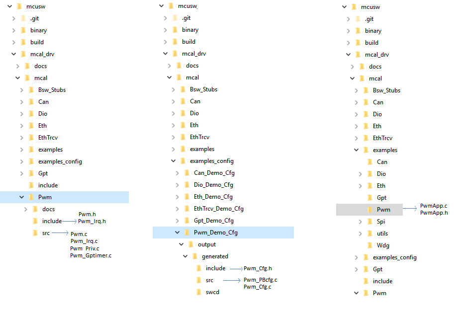
The Pwm Driver implementation supports multiple configuration variants (refer section Introduction), the driver expects generated Pwm_Cfg.h to be present as (File Structure). Please refer (Build) to specify path to generated configuration. The associated timer configuration generated files Pwm_Cfg.c and Pwm_PBcfg.c to be present as show (File Structure)
The following section details on the un-supported features and additional features added.
Note: AEP will not support EHRPWM feature because of hardware limitation.
APIs related to setting or getting power state of the device is not supported, as the hardware itself doesn’t support this feature.
To configure the clock source for Pwm (Timer/ePWM hardware), one would have to access/configure common registers. It’s recommended that clock sources for the Pwm (Timer/ePWM hardware) are done in SBL / Start up code. Please refer to example application.
The PWM_FIXED_PERIOD_SHIFTED, Pwm Channel Class type is not supported in this implementation.
This driver implementation introduces below listed configurable options
| Name | PwmDeviceVariant |
| Description | Used to specific family of devices, the variant of the device being used will belong one or more family of devices. Please refer (Supported Devices) to determine the family of device. Based on the family, the number of instances of Timer module supported could vary. |
| Container Name | PwmDriverConfiguration |
| Type | Enumeration |
| Range | J721E, J7200, etc… (new family of devices could be added in future) |
| Value Configuration Class | VARIANT-PRE-COMPILE |
| Name | PwmTypeofInterruptFunction |
| Description | Specifies category of ISR. |
| Container Name | PwmDriverConfiguration |
| Type | Enumeration |
| Range | PWM_ISR_CAT1 & PWM_ISR_CAT2 |
| Value Configuration Class | VARIANT-PRE-COMPILE |
| Note | This implementation has been validated with PWM_ISR_CAT1 only |
| Name | PwmDefaultOSCounterId |
| Description | Specifies the OS counter to be used by the driver. All wait operations (wait for hardware timer module reset to complete) are time bound. This implementation uses OS calls (GetCounterValue () & GetElapsedValue ()) to get current and elapsed time to establish time bound operation. In cases where a constant value is returned / OS call is not operational, the time bound operation cannot be realized. |
| Container Name | PwmDriverConfiguration |
| Type | Boolean |
| Value Configuration Class | VARIANT-PRE-COMPILE |
| Name | PwmEnableRegisterReadbackApi |
| Description | Adds / Removes service API Pwm_RegisterReadback () Safety feature : Some of the critical registers (corruption of which could potentially break functionality of the Pwm/Timer) The expected usage: Periodically this service API is invoked and checked for data-consistency. i.e. the values of members of structure Pwm_RegisterReadbackType is not expected to change. Also refer (@ref ug_pwm_functional_i_cfg_s_api_imp) |
| Container Name | PwmConfigurationOfOptApiServices |
| Type | Boolean |
| Value Configuration Class | VARIANT-PRE-COMPILE |
| Name | PwmClkPrescaler |
| Description | Used configure divider for the input clock This parameter could be used to divide this clock before it’s used to count. |
| Container Name | PwmChannelConfigSet |
| Type | uint8 |
| Range | 0 to 7 |
| Value Configuration Class | VARIANT-PRE-COMPILE & VARIANT-POST-BUILD |
| Name | PwmPolarity |
| Description | This parameter stores the initial polarity configured for a channel |
| Container Name | PwmChannelConfigSet |
| Type | Enummeration |
| Range | PWM_HIGH, PWM_LOW |
| Value Configuration Class | VARIANT-PRE-COMPILE & VARIANT-POST-BUILD |
| Name | PwmIdleState |
| Description | This parameter stores the initial polarity configured for a channel |
| Container Name | PwmChannelConfigSet |
| Type | Enummeration |
| Range | PWM_HIGH , PWM_LOW |
| Value Configuration Class | VARIANT-PRE-COMPILE & VARIANT-POST-BUILD |
| Name | PwmIndex |
| Description | Specifies the InstanceId of this module instance. |
| Container Name | PwmGeneral |
| Type | uint8 |
| Range | 0, 1 |
| Value Configuration Class | VARIANT-PRE-COMPILE & VARIANT-POST-BUILD |
| Name | PwmHSClkPrescaler |
| Description | Used configure divider for the input clock This parameter allows the selection of High Speed pre-scalar value. The High Speed prescaler stage is clocked with the pwm clock and acts as a clock divider for the time-base clock. |
| Container Name | PwmChannelConfigSet |
| Type | uint8 |
| Range | 0 to 7 |
| Value Configuration Class | VARIANT-PRE-COMPILE & VARIANT-POST-BUILD |
| Name | PwmEnableHighRes |
| Description | This parameter will be a switch to enable or disable high resolution (HRPWM) capability of EPWM module. |
| Container Name | PwmChannelConfigSet |
| Type | Boolean |
| Value Configuration Class | VARIANT-PRE-COMPILE & VARIANT-POST-BUILD |
| Name | PwmOutputChSelect |
| Description | PWM Output Channel select EPWMxA or EPWMxB or Both. Both Outputs available with same duty cycle, period and polarity. |
| Container Name | PwmChannelConfigSet |
| Type | Enummeration |
| Range | EPWM_OUTPUT_CH_A , EPWM_OUTPUT_CH_B, EPWM_OUTPUT_CH_BOTH_A_AND_B |
| Value Configuration Class | VARIANT-PRE-COMPILE & VARIANT-POST-BUILD |
To protect HW from un-intended re-configuration (corrupted / fault hardware), some of the critical registers are read periodically and checked. By an entity outside the driver, the values of these registers are not expected to change. This is an optional service API, which can be turned OFF (refer section PwmEnableRegisterReadbackApi)
| Service Name | Pwm_RegisterReadback |
| Syntax | void Pwm_RegisterReadback (Pwm_ChannelType PwmChannel, Pwm_RegisterReadbackType * RegRbPtr) |
| Service ID[hex] | 0x0F |
| Sync/Async | Synchronous |
| Reentrancy | Reentrant (but not for the same timer channel) |
| Parameters (in) | PwmChannel : Numeric identifier of the PWM channel |
| Parameters (inout) | RegRbPtr : Pointer of type Pwm_RegisterReadbackType |
| Parameters (out) | None |
| Return Value | E_OK: Register read back has been done E_NOT_OK: Register read back failed (if channel is not initialized or RegRbPtr is NULL_PTR |
| Description | Reads the important registers of the hardware unit and returns the value in the structure. |
The Driver doesn’t register any interrupts handler (ISR), it’s expected that consumer of this driver registers the required interrupt handler.
For every Pwm channel with notification enabled, an ISR requires to be registered. The Interrupt number associated with instance of the Timer or ePWM is detailed in TRM (also, please refer the demo application). Please refer PwmApp_InterruptConfig () in Pwm demo application.
Some of the Timer and ePWM interrupts are not routed/mapped to this core, these interrupts would require additional programming to route these to this core. Please refer PwmApp_InterruptConfig () in Pwm demo application.
Refer section (Pwm Channel ID , Instance mapping and ISR mapping), for association between channel ID and ISR
The driver doesn't configure the functional clock and power for the timer modules. Its expected that SBL power-up the required modules. Please refer SBL documentation.
Please follow steps detailed in section (Build) to build library or example.
Please note that a clean build for building these applications. Building both together will cause build errors. Build only one at a time.
Please refer (Running Examples)
Various objects of this implementation (e.g. variables, functions, constants) are defined under different sections. The linker command file at (Examples Linker File (Select memory location to hold example binary)) defines separate section for these objects. When the driver is integrated, its expected that these sections are created and placed in appropriate memory locations. (Locations of these objects depend on the system design and performance needs)
| Section | PWM_CODE | PWM_VAR_INIT | PWM_VAR_NOINIT | PWM_CONST | PWM_CONFIG |
| PWM_START_SEC_VAR_INIT_UNSPECIFIED (.data) | USED | ||||
| PWM_DATA_INIT_32_SECTION | USED | ||||
| PWM_TEXT_SECTION | USED | ||||
| PWM_DATA_NO_INIT_UNSPECIFIED_SECTION | USED | ||||
| PWM_CONST_32_SECTION | USED | ||||
| PWM_ISR_TEXT_SECTION | USED | ||||
| PWM_CONFIG_SECTION | USED |
This driver implementation has been validated with cache enabled. For optimal performance it’s recommended to place (Memory Mapping) sections in cache enabled memory area.
Setting Prescalers: Period value(Num of ticks) which determines the period is calculated using below formula:
Actual Division Value = / ( 1 << CLKDIV) i.e
| Actual Division Value | CLKDIV Value |
|---|---|
| 0x0 | / 1 |
| 0x1 | / 2 |
| 0x2 | / 4 |
| 0x3 | / 8 |
| 0x4 | / 16 |
| 0x5 | / 32 |
| 0x6 | / 64 |
| 0x7 | / 128 |
Actual Division Value = / (HSPCLKDIV * 2) i.e
| Actual Division Value | HSPCLKDIV |
|---|---|
| 0x0 | / 1 |
| 0x1 | / 2 |
| 0x2 | / 4 |
| 0x3 | / 6 |
| 0x4 | / 8 |
| 0x5 | / 10 |
| 0x6 | / 12 |
| 0x7 | / 14 |
There is a chance that period value calculated is fractional, and therefore required frequency cannot be achieved. The clock dividers need to be selected correctly to avoid such errors. Please refer to the excel sheet provided to derive the correct CLKDIV and HSPCLKDIV values. Using this excel, you can test prescaler combinations with required frequency and ensure that the "Difference" is 0. The Period value should be less than or equal to 65535 (16bit HW register size for period).
Find the excel sheet here: <../../mcusw/mcal_drv/docs/Pwm_Frequency_Prescalers.xlsx>
User/Application need to note that these prescalers are configured in Pwm_Init time and cannot be changed run time. User has to consider same prescaler values, configure new period and need to see whether new period can be achieved or not using above excel.
In case if user is not able to set new period with the same prescalers combination then he need to call Pwm_DeInit and call Pwm_Init with the new prescalers combination which helps in achieving required period.
This implementation depends on the DET in order to report development errors and can be turned OFF. Refer section (Development Error Reporting) for detailed error codes.
This implementation requires 1 level of exclusive access to guard critical sections. Invokes SchM_Enter_Pwm_PWM_EXCLUSIVE_AREA_0 (), SchM_Exit_Pwm_PWM_EXCLUSIVE_AREA_0 () to enter critical section and exit.
In the example implementation (File Structure SchM_Pwm.c) , all the interrupts on CPU are disabled. However, disabling of the enabled Timer/Pwm interrupt should suffice.
Development errors are reported to the DET using the service Det_ReportError(), when enabled. The driver interface (Pwm.h File Structure) lists the SID
| Type of Error | Related Error code | Value (Hex) |
| API Pwm_Init service called with wrong parameter | PWM_E_PARAM_CONFIG | 0x10 |
| API service used without module initialization | PWM_E_UNINIT | 0x11 |
| API service used with an invalid channel Identifier | PWM_E_PARAM_CHANNEL | 0x12 |
| Usage of unauthorized PWM service on PWM channel configured a fixed period | PWM_E_PERIOD_UNCHANGEABLE | 0x13 |
| API Pwm_Init service called while the PWM driver has already been initialised | PWM_E_ALREADY_INITIALIZED | 0x14 |
| API Pwm_GetVersionInfo is called with a NULL parameter. | PWM_E_PARAM_POINTER | 0x15 |
The AUTOSAR BSW PWM Driver specification details the APIs required for Pwm Driver. Please refer to PWM Design Document for detailed API description. APIs related to setting/ getting the power state are not implemented, please refer to (Variance / Deviation from the specification). Also refer to (Non Standard Service APIs) for non-standard APIs which are included in this implemented.
Refer API Documentation for details
The example application demonstrate use of Timer based Pwm module, the list below identifies key steps performed the example. The configuration file is present at (File Structure) The timer Test Point TP97 on J721E EVM can be probed to check the output PWM signales. The timer Test Point TP82 on J721S2 EVM can be probed to check the output PWM signales. The timer Test Point TP93 on J784S4 EVM can be probed to check the output PWM signales. The timer pins will change based on the EVM used, (J5F Pin F15)in J7200 EVM
The example application demonstrate use of ePWM based Pwm module, the list below identifies key steps performed the example. The configuration file is present at (File Structure)
        PWM_APP_GPT: Sample Application - STARTS !!!

        PWM_APP_GPT: PWM MCAL Version Info
        ---------------------
        PWM_APP_GPT: Vendor ID           : 44
        PWM_APP_GPT: Module ID           : 121
        PWM_APP_GPT: SW Major Version    : 1
        PWM_APP_GPT: SW Minor Version    : 2
        PWM_APP_GPT: SW Patch Version    : 1

        PWM_APP_GPT: Variant - Pre Compile being used !!!

        PWM_APP_GPT: PWM Channel Initialized
        PWM_APP_GPT: PWM Duty cycle: 50 Percent, PWM Period: 1 sec
        PWM_APP_GPT: Probe TIMER in Main domain(Test Point TP97)in J721E EVM
        PWM_APP_GPT: This example waits for 10 seconds please probe

        PWM_APP_GPT: Changing the Duty cycle from 50 Percent to 80 Percent
        PWM_APP_GPT: This example waits for 10 seconds Please probe

        PWM_APP_GPT: Setting Output to Idle state
        PWM_APP_GPT: This example waits for 10 seconds Please probe

        PWM_APP_GPT: Changing PWM Period from 1s to 500 ms and Duty Cycle to 50%
        PWM_APP_GPT: This example waits for 10 seconds Please probe

        PWM_APP_GPT: This example waits for 10 seconds please probe
        PWM_APP_GPT: Pwm Isr Count: 20

        PWM_APP_GPT: Disabling Notifications for PWM channel
        PWM_APP_GPT: PWM De-initialized
        PWM_APP_GPT: Pwm Stack Usage 1116 bytes
PWM_APP_GPT: PWM Test Passed!!! PWM_APP_GPT: Sample Application - STARTS !!!
PWM_APP_GPT: PWM MCAL Version Info
---------------------
PWM_APP_GPT: Vendor ID : 44
PWM_APP_GPT: Module ID : 121
PWM_APP_GPT: SW Major Version : 1
PWM_APP_GPT: SW Minor Version : 2
PWM_APP_GPT: SW Patch Version : 1
PWM_APP_GPT: Variant - Pre Compile being used !!!
PWM_APP_GPT: PWM Channel Initialized
PWM_APP_GPT: PWM Duty cycle: 50 Percent, PWM Period: 1 sec
PWM_APP_GPT: Probe TIMER in Main domain(J5F Pin F15)in J7200 EVM
PWM_APP_GPT: This example waits for 10 seconds please probe
PWM_APP_GPT: Changing the Duty cycle from 50 Percent to 80 Percent
PWM_APP_GPT: This example waits for 10 seconds Please probe
PWM_APP_GPT: Setting Output to Idle state
PWM_APP_GPT: This example waits for 10 seconds Please probe
PWM_APP_GPT: Changing PWM Period from 1s to 500 ms and Duty Cycle to 50%
PWM_APP_GPT: This example waits for 10 seconds Please probe
PWM_APP_GPT: This example waits for 10 seconds please probe
PWM_APP_GPT: Pwm Isr Count: 20
PWM_APP_GPT: Disabling Notifications for PWM channel
PWM_APP_GPT: PWM De-initialized
PWM_APP_GPT: Pwm Stack Usage 1116 bytes
PWM_APP_GPT: PWM Test Passed!!! PWM_APP_EPWM: Sample Application - STARTS !!!
PWM_APP_EPWM: EPWM being used with Channel # 1!!!
PWM_APP_EPWM: PWM MCAL Version Info
---------------------
PWM_APP_EPWM: Vendor ID : 44
PWM_APP_EPWM: Module ID : 121
PWM_APP_EPWM: SW Major Version : 1
PWM_APP_EPWM: SW Minor Version : 2
PWM_APP_EPWM: SW Patch Version : 1
PWM_APP_EPWM: Variant - Pre Compile being used !!!
PWM_APP_EPWM: PWM Channel Initialized
PWM_APP_EPWM: PWM Duty cycle: 60 Percent, 1000Hz
PWM_APP_EPWM: Probe EPWM in Main domain(Test Connector Pin 11 or 2 on GESI Board (A or B)) in J721E EVM and J7200 EVM
PWM_APP_EPWM: This example waits for 30 seconds please probe
PWM_APP_EPWM: Changing the Duty cycle from to 60 to 80 percent
PWM_APP_EPWM: This example waits for 30 seconds Please probe
PWM_APP_EPWM: Changing the Duty cycle to 100 Percent
PWM_APP_EPWM: This example waits for 10 seconds Please probe
PWM_APP_EPWM: Setting Output to Idle state
PWM_APP_EPWM: This example waits for 10 seconds Please probe
PWM_APP_EPWM: Changing Frequency from 1kHz to 10KHz and Duty Cycle to 50%
PWM_APP_EPWM: period is set to 6250
PWM_APP_EPWM: This app again waits for 30 seconds please probe
PWM_APP_EPWM: Pwm Isr Count: 300000
PWM_APP_EPWM: App Run time: 29934858 micro secs
PWM_APP_EPWM: Disabling Notifications for PWM channel
PWM_APP_EPWM: Changing Frequency from 10kHz to 1.25MHz and Duty Cycle to 40.5%
PWM_APP_EPWM: period is set to 50
PWM_APP_EPWM: This app again waits for 30 seconds please probe
PWM_APP_EPWM: Pwm Stack Usage 1124 bytes
PWM_APP_EPWM: PWM Test Passed!!! PWM_APP_EPWM: Sample Application - STARTS !!!
PWM_APP_EPWM: EPWM being used with Channel # 1!!!
PWM_APP_EPWM: PWM MCAL Version Info
---------------------
PWM_APP_EPWM: Vendor ID : 44
PWM_APP_EPWM: Module ID : 121
PWM_APP_EPWM: SW Major Version : 1
PWM_APP_EPWM: SW Minor Version : 2
PWM_APP_EPWM: SW Patch Version : 1
PWM_APP_EPWM: Variant - Pre Compile being used !!!
PWM_APP_EPWM: PWM Channel Initialized
PWM_APP_EPWM: PWM Duty cycle: 60 Percent, 1000Hz
PWM_APP_EPWM: Probe EPWM in Main domain(Test Connector Pin 11 or 2 on GESI BoarM
PWM_APP_EPWM: This example waits for 30 seconds please probe
PWM_APP_EPWM: Changing the Duty cycle from to 60 to 80 percent
PWM_APP_EPWM: This example waits for 30 seconds Please probe
PWM_APP_EPWM: Changing the Duty cycle to 100 Percent
PWM_APP_EPWM: This example waits for 10 seconds Please probe
PWM_APP_EPWM: Setting Output to Idle state
PWM_APP_EPWM: This example waits for 10 seconds Please probe
PWM_APP_EPWM: Changing Frequency from 1kHz to 10KHz and Duty Cycle to 50%
PWM_APP_EPWM: period is set to 6250
PWM_APP_EPWM: This app again waits for 30 seconds please probe
PWM_APP_EPWM: Pwm Isr Count: 300000
PWM_APP_EPWM: App Run time: 29935036 micro secs
PWM_APP_EPWM: Disabling Notifications for PWM channel
PWM_APP_EPWM: Changing Frequency from 10kHz to 1.25MHz and Duty Cycle to 40.5%
PWM_APP_EPWM: period is set to 50
PWM_APP_EPWM: This app again waits for 30 seconds please probe
PWM_APP_EPWM: Pwm Stack Usage 1124 bytes
PWM_APP_EPWM: PWM Test Passed!!!
| Revision | Date | Author | Description | Status |
|---|---|---|---|---|
| 0.1 | 03 April 2019 | Vibha Pant | First version | Pending Review |
| 0.2 | 15 April 2019 | Vibha Pant | Addressed review comments | Approved |
| 0.3 | 16 Oct 2018 | Sujith S | Added Logs from J721E testing | Approved |
| 0.4 | 03 Nov 2020 | Nikki S | Adding EPWM User Guide + J7200 Updates | Approved |
| 0.5 | 08 Dec 2022 | Subham Swain | Adding J721S2 | Approved |
| 0.6 | 07 Feb 2023 | Subham Swain | Adding J784S4 | Approved |
| 0.7 | 10 April 2023 | Rohit T | Fixed doxygen warnings | Approved |
| 0.8 | 09 Nov 2023 | Pradeep K | Updated EPWM pin details for J7200,J721E,J784S4 and J721S2 | Approved |
 1.8.15