

|
|
ADCBuf driver implementation for a MSP432E4 analog-to-digital converter.
This driver takes n samples using the ADC and stores the results in a buffer. This implementation supports both ADCBuf_RECURRENCE_MODE_ONE_SHOT and ADCBuf_RECURRENCE_MODE_CONTINUOUS. The ADCBuf_MSP432E4 driver supports use of both ADC peripherals and their sample sequencers.
The MSP342E4 microcontroller has two ADC modules and each ADC module has four sample sequencers, SS0-SS3, that control and capture sample data. Sequencer priority can be initialized in ADCBufMSP432E4_HWAttrsV1 by creating an array that holds the corresponding ADCBufMSP432E4_SequencePriorities.
To initialize the sequencers, in the board file "MSP_EXP432E401Y.c"/board.h
The MSP432E4 ADC sample sequencers can be triggered by several different types of software and hardware events. The driver currently only supports ADCBufMSP432E4_SOFTWARE_AUTOMATIC_TRIGGER and ADCBufMSP432E4_TIMER_TRIGGER trigger sources. Multiple sequencers can share the same trigger source. An unique ADCBufMSP432E4_TriggerSource array can be defined for each ADCBuf instance. That is, each ADCBufMSP432E4_HWAttrsV1.adcTriggerSource can point to a unique ADCBufMSP432E4_TriggerSource array.
The application is responsible for defining a ADCBufMSP432E4_Channels array. Each index corresponds to a ADC channel configuration. A unique ADCBufMSP432E4_Channels array can be defined for each ADCBuf instance. That is, each ADCBufMSP432E4_HWAttrsV1.channelSetting can point to a unique ADCBufMSP432E4_Channels array.
The ADCBufMSP432E4_Channels array lets the user select the ADCBufMSP432E4_Sequencer, ADCBufMSP432E4_DifferentialMode, the differential pins if needed, MSP432E4 specific ADC modes like ADCBufMSP432E4_TEMPERATURE_MODE that let the user configure the internal temperature mode
## Channel section - ADCBufMSP432E4_Channels
Please refer to ADCBufMSP432E4_HWAttrsV1 structure for other hardware dependent configuration settings Some examples include voltage reference source selection and optional DMA usage.
This driver supports various modes of operation and sampling. ADCBufMSP432E4_HWAttrsV1.useDMA can be set to 1 to improve performance. Additionally, samples can be performed using ADCBufMSP432E4_DIFFERENTIAL or ADCBufMSP432E4_TEMPERATURE_MODE modes.
In the application,
Refer to ADCBuf.h for a complete description of APIs & example use.
#include <stdint.h>#include <stdbool.h>#include <ti/drivers/ADCBuf.h>#include <ti/drivers/dpl/HwiP.h>#include <ti/drivers/dpl/SemaphoreP.h>#include <ti/drivers/dma/UDMAMSP432E4.h>#include <ti/devices/msp432e4/driverlib/adc.h>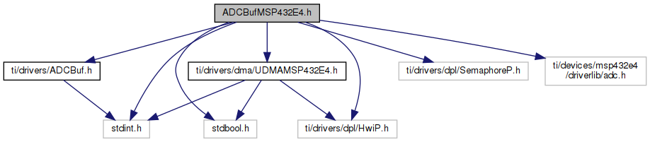
Go to the source code of this file.
Data Structures | |
| struct | ADCBufMSP432E4_ParamsExtension |
| MSP432E4 ADCBuf_Params Parameter Extensions. More... | |
| struct | ADCBufMSP432E4_Channels |
| ADCBufMSP432E4 Channel Settings. More... | |
| struct | ADCBufMSP432E4_HWAttrsV1 |
| ADCBufMSP432E4 Hardware attributes. More... | |
| struct | ADCBufMSP432E4_Object |
Macros | |
| #define | MSP432E4_NUM_ADC_CHANNELS (24) |
| #define | ADCBufMSP432E4_SEQUENCER_COUNT 4 |
PB4, Analog Channel 10 | |
| #define | ADCBufMSP432E4_PB_4_A10 ((10 << 16) | 0x5910) |
PB5, Analog Channel 11 | |
| #define | ADCBufMSP432E4_PB_5_A11 ((11 << 16) | 0x5920) |
PD0, Analog Channel 15 | |
| #define | ADCBufMSP432E4_PD_0_A15 ((15 << 16) | 0x5B01) |
PD1, Analog Channel 14 | |
| #define | ADCBufMSP432E4_PD_1_A14 ((14 << 16) | 0x5B02) |
PD2, Analog Channel 13 | |
| #define | ADCBufMSP432E4_PD_2_A13 ((13 << 16) | 0x5B04) |
PD3, Analog Channel 12 | |
| #define | ADCBufMSP432E4_PD_3_A12 ((12 << 16) | 0x5B08) |
PD4, Analog Channel 7 | |
| #define | ADCBufMSP432E4_PD_4_A7 ((7 << 16) | 0x5B10) |
PD5, Analog Channel 6 | |
| #define | ADCBufMSP432E4_PD_5_A6 ((6 << 16) | 0x5B20) |
PD6, Analog Channel 5 | |
| #define | ADCBufMSP432E4_PD_6_A5 ((5 << 16) | 0x5B40) |
PD7, Analog Channel 4 | |
| #define | ADCBufMSP432E4_PD_7_A4 ((4 << 16) | 0x5B80) |
PE0, Analog Channel 3 | |
| #define | ADCBufMSP432E4_PE_0_A3 ((3 << 16) | 0x5C01) |
PE1, Analog Channel 2 | |
| #define | ADCBufMSP432E4_PE_1_A2 ((2 << 16) | 0x5C02) |
PE2, Analog Channel 1 | |
| #define | ADCBufMSP432E4_PE_2_A1 ((1 << 16) | 0x5C04) |
PE3, Analog Channel 0 | |
| #define | ADCBufMSP432E4_PE_3_A0 ((0 << 16) | 0x5C08) |
PE4, Analog Channel 9 | |
| #define | ADCBufMSP432E4_PE_4_A9 ((9 << 16) | 0x5C10) |
PE5, Analog Channel 8 | |
| #define | ADCBufMSP432E4_PE_5_A8 ((8 << 16) | 0x5C20) |
PE6, Analog Channel 20 | |
| #define | ADCBufMSP432E4_PE_6_A20 (((20-16) << 16) | 0x5C40 | 0x01000000) |
PE7, Analog Channel 21 | |
| #define | ADCBufMSP432E4_PE_7_A21 (((21-16) << 16) | 0x5C80 | 0x01000000) |
PK0, Analog Channel 16 | |
| #define | ADCBufMSP432E4_PK_0_A16 (((16-16) << 16) | 0x6101 | 0x01000000) |
PK1, Analog Channel 17 | |
| #define | ADCBufMSP432E4_PK_1_A17 (((17-16) << 16) | 0x6102 | 0x01000000) |
PK2, Analog Channel 18 | |
| #define | ADCBufMSP432E4_PK_2_A18 (((18-16) << 16) | 0x6104 | 0x01000000) |
PK3, Analog Channel 19 | |
| #define | ADCBufMSP432E4_PK_3_A19 (((19-16) << 16) | 0x6108 | 0x01000000) |
PP6, Analog Channel 23 | |
| #define | ADCBufMSP432E4_PP_6_A23 (((23-16) << 16) | 0x6540 | 0x01000000) |
PP7, Analog Channel 22 | |
| #define | ADCBufMSP432E4_PP_7_A22 (((22-16) << 16) | 0x6580 | 0x01000000) |
PIN NONE. | |
| #define | ADCBufMSP432E4_PIN_NONE 0 |
Variables | |
| const ADCBuf_FxnTable | ADCBufMSP432E4_fxnTable |
| #define MSP432E4_NUM_ADC_CHANNELS (24) |
Number of available ADC channels
| #define ADCBufMSP432E4_SEQUENCER_COUNT 4 |
Number of ADCBufMSP432E4_Sequencer per peripheral
ADCBufMSP432E4 Sequencer Priorities.
The application is responsible for defining a ADCBufMSP432E4_SequencePriorities array of ADCBufMSP432E4_SEQUENCER_COUNT length. Each index corresponds to one of the four sequencers respectively. A unique ADCBufMSP432E4_SequencePriorities array can be defined for each ADCBuf instance. That is, each ADCBufMSP432E4_HWAttrsV1.sequencePriority can point to a unique ADCBufMSP432E4_TriggerSource array.
A sequencer's priority is set by assigning its respective index to one of the ADCBufMSP432E4_SequencePriorities definitions. Multiple sequencers can share the same priority.
In the code example below, sequencer 0 and sequencer 2 have a priority of ADCBufMSP432E4_Priority_3. Sequencer 1 has a priority of ADCBufMSP432E4_Priority_0. Sequencer 3 is disabled.
ADCBufMSP432E4 Sequencer.
These fields are used to assign a sequencer to a channel by using the ADCBufMSP432E4_Channels.adcSequence field. Each sequencer can only support a limited number of ADC channels. It is the applications responsibility to ensure an appropriate number of channels are assigned to each sequencer. Assigning more ADC channels than a sequencer can support may lead to undefined behavior. Each ADC peripheral has dedicated sequencers.
ADCBufMSP432E4 Internal Source Mode.
These fields are used by ADCBufMSP432E4_Channels.adcInternalSource to specify if an internal source mode is selected. If using an internal source, ADCBufMSP432E4_Channels.adcInputMode must be set to ADCBufMSP432E4_SINGLE_ENDED.
| Enumerator | |
|---|---|
| ADCBufMSP432E4_INTERNAL_SOURCE_MODE_OFF | No internal source mode is used |
| ADCBufMSP432E4_TEMPERATURE_MODE | The ADC will sample the internal temperature. The ADCBufMSP432E4_Channels.adcPin should be set to ADCBufMSP432E4_PIN_NONE |
ADCBufMSP432E4 Differential Mode.
These fields are used by ADCBufMSP432E4_Channels.adcInputMode to specify if a differential sampling mode is selected. If using the differential sampling mode, ADCBufMSP432E4_Channels.adcInternalSource must be set to ADCBufMSP432E4_INTERNAL_SOURCE_MODE_OFF.
| Enumerator | |
|---|---|
| ADCBufMSP432E4_SINGLE_ENDED | Use single ended sampling mode |
| ADCBufMSP432E4_DIFFERENTIAL | Use differential sampling mode. The ADC will measure the voltage difference between two channels. The user is responsible for setting the ADCBufMSP432E4_Channels.adcDifferentialPin. |
ADCBufMSP432E4 Trigger Source.
The application is responsible for defining a ADCBufMSP432E4_TriggerSource array of ADCBufMSP432E4_SEQUENCER_COUNT length. Each index corresponds to one of the four sequencers respectively. A unique ADCBufMSP432E4_TriggerSource array can be defined for each ADCBuf instance. That is, each ADCBufMSP432E4_HWAttrsV1.adcTriggerSource can point to a unique ADCBufMSP432E4_TriggerSource array.
A sequencer's trigger source is set by assigning its respective index to one of the ADCBufMSP432E4_TriggerSource definitions. Multiple sequencers can share the same trigger source.
In the code example below, sequencer 0, sequencer 2 and sequencer 3 have a trigger source of ADCBufMSP432E4_TIMER_TRIGGER. Sequencer 1 has a trigger source of ADCBufMSP432E4_SOFTWARE_AUTOMATIC_TRIGGER.
| Enumerator | |
|---|---|
| ADCBufMSP432E4_SOFTWARE_AUTOMATIC_TRIGGER | Automatically and continuously trigger ADC sampling. Precaution should be taken when using this mode with multiple sequencers. If the sequencer's priority using the software trigger is too high, it is possible to starve other lower priority sequencers. Generally, a sequencer using ADCBufMSP432E4_SOFTWARE_AUTOMATIC_TRIGGER should be set to the lowest priority. |
| ADCBufMSP432E4_TIMER_TRIGGER | Trigger ADC samples using a general purpose timer. When using both ADC peripherals, both must be initialized to use the same general purpose timer. The application is responsible for providing ADCBufMSP432E4_HWAttrsV1.adcTimerSource. |
| enum ADCBufMSP432E4_Phase |
ADCBufMSP432E4 phase delay.
These fields are used by ADCBufMSP432E4_HWAttrsV1 to specify the phase delay between a trigger and the start of a sequence for the ADC module. By selecting a different phase delay for a pair of ADC modules (such as ADCBufMSP432E4_Phase_Delay_0 and ADCBufMSP432E4_Phase_Delay_180) and having each ADC module sample the same analog input, it is possible to increase the sampling rate of the analog input (with samples N, N+2, N+4, and so on, coming from the first ADC and samples N+1, N+3, N+5, and so on, coming from the second ADC). The ADC module has a single phase delay that is applied to all sample sequences within that module.
ADCMSP432E4 Sampling Duration.
These fields define the sample and hold time in the pulse width units. The application can specify the sampling duration at runtime using the ADCBufMSP432E4_ParamsExtension.samplingDuration field. The ADC clock is the same as the system clock.
ADCBufMSP432E4 Reference Source.
These fields are used by ADCBufMSP432E4_HWAttrsV1.refSource to specify the reference source for the ADC peripheral. This is therefore shared amongst all channels for an ADCBuf instance.
| Enumerator | |
|---|---|
| ADCBufMSP432E4_VREF_INTERNAL | Use internal reference voltage source of 3V. |
| ADCBufMSP432E4_VREF_EXTERNAL_3V | Use an external 3V reference source supplied to the AVREF pin. |
| const ADCBuf_FxnTable ADCBufMSP432E4_fxnTable |