Data Structures
GPIOMSP432.h File Reference

Detailed Description

GPIO driver implementation for MSP432 devices.

============================================================================

The GPIO header file should be included in an application as follows:

Refer to GPIO.h for a complete description of the GPIO driver APIs provided and examples of their use.

MSP432 GPIO Driver Configuration

In order to use the GPIO APIs, the application is required to provide 3 structures in the ti_drivers_config.c file:

  1. An array of GPIO_PinConfig elements that defines the initial configuration of each pin used by the application. A pin is referenced in the application by its corresponding index in this array. The pin type (that is, INPUT/OUTPUT), its initial state (that is OUTPUT_HIGH or LOW), interrupt behavior (RISING/FALLING edge, etc.) (see Macros used to configure GPIO pins), and device specific pin identification (see GPIO pin identification macros used to configure GPIO pins) are configured in each element of this array. Below is an MSP432 device specific example of the GPIO_PinConfig array:
    //
    // Array of Pin configurations
    // NOTE: The order of the pin configurations must coincide with what was
    // defined in MSP_EXP432P401R.h
    // NOTE: Pins not used for interrupts should be placed at the end of the
    // array. Callback entries can be omitted from callbacks array to
    // reduce memory usage.
    //
    GPIO_PinConfig gpioPinConfigs[] = {
    // Input pins
    // MSP_EXP432P401R_GPIO_S1
    // MSP_EXP432P401R_GPIO_S2
    // Output pins
    // MSP_EXP432P401R_GPIO_LED1
    // MSP_EXP432P401R_GPIO_LED_RED
    };
  2. An array of GPIO_CallbackFxn elements that is used to store callback function pointers for GPIO pins configured with interrupts. The indexes for these array elements correspond to the pins defined in the GPIO_PinConfig array. These function pointers can be defined statically by referencing the callback function name in the array element, or dynamically, by setting the array element to NULL and using GPIO_setCallback() at runtime to plug the callback entry. Pins not used for interrupts can be omitted from the callback array to reduce memory usage (if they are placed at the end of the GPIO_PinConfig array). The callback function syntax should match the following:
    void (*GPIO_CallbackFxn)(unsigned int index);
    The index parameter is the same index that was passed to GPIO_setCallback(). This allows the same callback function to be used for multiple GPIO interrupts, by using the index to identify the GPIO that caused the interrupt. Below is an MSP432 device specific example of the GPIO_CallbackFxn array:
    //
    // Array of callback function pointers
    // NOTE: The order of the pin configurations must coincide with what was
    // defined in MSP_EXP432P401R.h
    // NOTE: Pins not used for interrupts can be omitted from callbacks array
    // to reduce memory usage (if placed at end of gpioPinConfigs
    // array).
    //
    GPIO_CallbackFxn gpioCallbackFunctions[] = {
    // MSP_EXP432P401R_GPIO_S1
    NULL,
    // MSP_EXP432P401R_GPIO_S2
    NULL
    };
  3. The device specific GPIOMSP432_Config structure that tells the GPIO driver where the two aforementioned arrays are and the number of elements in each. The interrupt priority of all pins configured to generate interrupts is also specified here. Values for the interrupt priority are device-specific. You should be well-acquainted with the interrupt controller used in your device before setting this parameter to a non-default value. The sentinel value of (~0) (the default value) is used to indicate that the lowest possible priority should be used. Below is an example of an initialized GPIOMSP432_Config structure:
    const GPIOMSP432_Config GPIOMSP432_config = {
    .pinConfigs = (GPIO_PinConfig *)gpioPinConfigs,
    .callbacks = (GPIO_CallbackFxn *)gpioCallbackFunctions,
    .numberOfPinConfigs = sizeof(gpioPinConfigs)/sizeof(GPIO_PinConfig),
    .numberOfCallbacks = sizeof(gpioCallbackFunctions)/sizeof(GPIO_CallbackFxn),
    .intPriority = (~0)
    };

Drive Strength Limitation

Only pins 2.0 thru 2.3 support high output drive strength. All other pins only support low drive strength. For pins that do not support high output drive strength, the GPIO_CFG_OUT_STR_XXX setting is ignored.


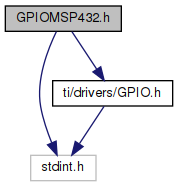
#include <stdint.h>
#include <ti/drivers/GPIO.h>
Include dependency graph for GPIOMSP432.h:

Go to the source code of this file.

Data Structures

struct  GPIOMSP432_Config
 GPIO device specific driver configuration structure. More...
 

Macros

Device specific GPIO port/pin identifiers to be used within the board's GPIO_PinConfig table.
#define GPIOMSP432_EMPTY_PIN
 
Only ports 1-6 support interrupts and can be configured with callbacks
#define GPIOMSP432_P1_0
 
#define GPIOMSP432_P1_1
 
#define GPIOMSP432_P1_2
 
#define GPIOMSP432_P1_3
 
#define GPIOMSP432_P1_4
 
#define GPIOMSP432_P1_5
 
#define GPIOMSP432_P1_6
 
#define GPIOMSP432_P1_7
 
#define GPIOMSP432_P2_0
 
#define GPIOMSP432_P2_1
 
#define GPIOMSP432_P2_2
 
#define GPIOMSP432_P2_3
 
#define GPIOMSP432_P2_4
 
#define GPIOMSP432_P2_5
 
#define GPIOMSP432_P2_6
 
#define GPIOMSP432_P2_7
 
#define GPIOMSP432_P3_0
 
#define GPIOMSP432_P3_1
 
#define GPIOMSP432_P3_2
 
#define GPIOMSP432_P3_3
 
#define GPIOMSP432_P3_4
 
#define GPIOMSP432_P3_5
 
#define GPIOMSP432_P3_6
 
#define GPIOMSP432_P3_7
 
#define GPIOMSP432_P4_0
 
#define GPIOMSP432_P4_1
 
#define GPIOMSP432_P4_2
 
#define GPIOMSP432_P4_3
 
#define GPIOMSP432_P4_4
 
#define GPIOMSP432_P4_5
 
#define GPIOMSP432_P4_6
 
#define GPIOMSP432_P4_7
 
#define GPIOMSP432_P5_0
 
#define GPIOMSP432_P5_1
 
#define GPIOMSP432_P5_2
 
#define GPIOMSP432_P5_3
 
#define GPIOMSP432_P5_4
 
#define GPIOMSP432_P5_5
 
#define GPIOMSP432_P5_6
 
#define GPIOMSP432_P5_7
 
#define GPIOMSP432_P6_0
 
#define GPIOMSP432_P6_1
 
#define GPIOMSP432_P6_2
 
#define GPIOMSP432_P6_3
 
#define GPIOMSP432_P6_4
 
#define GPIOMSP432_P6_5
 
#define GPIOMSP432_P6_6
 
#define GPIOMSP432_P6_7
 
Ports 7-10 and 'J' do NOT support interrupts.
#define GPIOMSP432_P7_0
 
#define GPIOMSP432_P7_1
 
#define GPIOMSP432_P7_2
 
#define GPIOMSP432_P7_3
 
#define GPIOMSP432_P7_4
 
#define GPIOMSP432_P7_5
 
#define GPIOMSP432_P7_6
 
#define GPIOMSP432_P7_7
 
#define GPIOMSP432_P8_0
 
#define GPIOMSP432_P8_1
 
#define GPIOMSP432_P8_2
 
#define GPIOMSP432_P8_3
 
#define GPIOMSP432_P8_4
 
#define GPIOMSP432_P8_5
 
#define GPIOMSP432_P8_6
 
#define GPIOMSP432_P8_7
 
#define GPIOMSP432_P9_0
 
#define GPIOMSP432_P9_1
 
#define GPIOMSP432_P9_2
 
#define GPIOMSP432_P9_3
 
#define GPIOMSP432_P9_4
 
#define GPIOMSP432_P9_5
 
#define GPIOMSP432_P9_6
 
#define GPIOMSP432_P9_7
 
#define GPIOMSP432_P10_0
 
#define GPIOMSP432_P10_1
 
#define GPIOMSP432_P10_2
 
#define GPIOMSP432_P10_3
 
#define GPIOMSP432_P10_4
 
#define GPIOMSP432_P10_5
 
#define GPIOMSP432_P10_6
 
#define GPIOMSP432_P10_7
 
#define GPIOMSP432_PJ_0
 
#define GPIOMSP432_PJ_1
 
#define GPIOMSP432_PJ_2
 
#define GPIOMSP432_PJ_3
 
#define GPIOMSP432_PJ_4
 
#define GPIOMSP432_PJ_5
 
#define GPIOMSP432_PJ_6
 
#define GPIOMSP432_PJ_7
 
© Copyright 1995-2019, Texas Instruments Incorporated. All rights reserved.
Trademarks | Privacy policy | Terms of use | Terms of sale