BLE5-Stack SysConfig Features
Checking if SysConfig is used for BLE
Projects that are using SysConfig to configure BLE will have a green check mark next to BLE as shown in the green rectangle, while others will have a green check mark next to Custom, shown in the red rectangle.
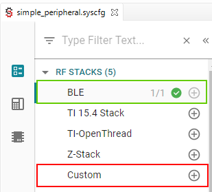
Figure 202. Check for SysConfig enabled example applications
Note
Get started with SysConfig provides an overview of what SysCfg is and how to get started with it. Please take a look at this if you have not already.
After importing a BLE5-Stack SysCfg project into CCS, by double clicking on the *.syscfg
file, a GUI will appear where the project can be configured more easily. A number
of BLE5-Stack configurable features are included in this GUI. Figure 203.
shows what this looks like when importing the multi_role example.
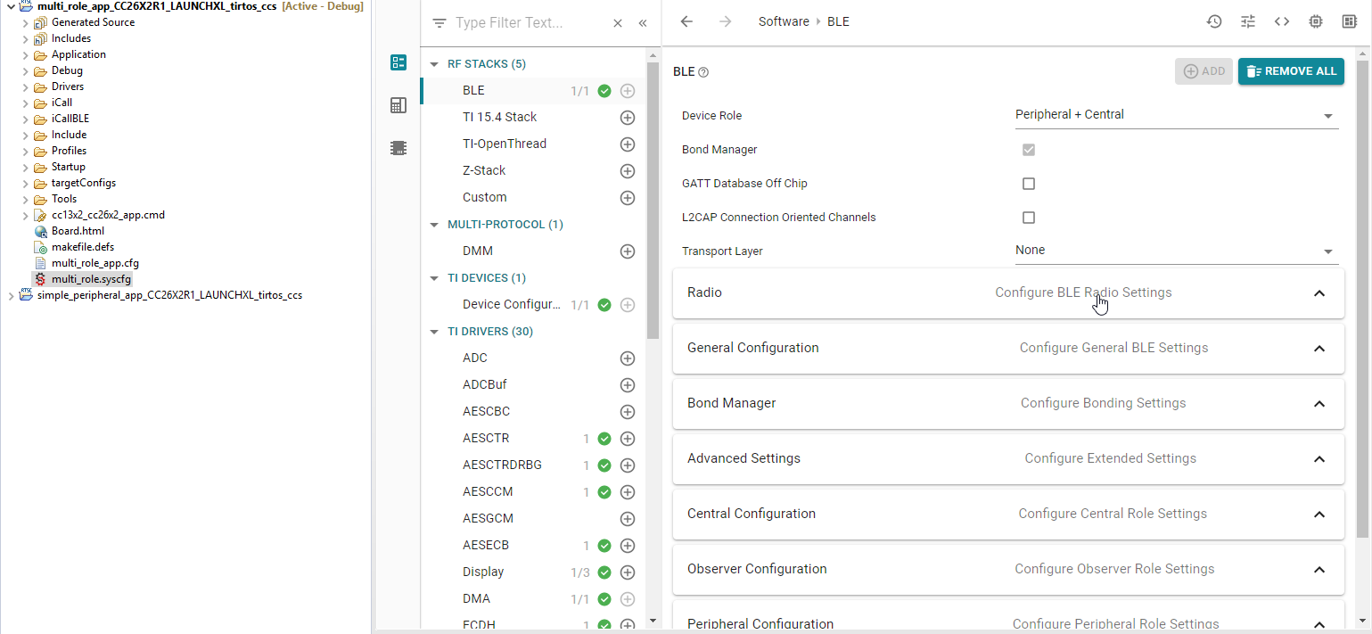
Figure 203. After Import
Figure 203. Also shows many different configurable parameters
for the project. The first few configurable options inside the Software -> BLE
pane are the Device Role, Bond Manager, GATT Database Off Chip,
L2CAP Connection Oriented Channels and Transport Layer options.
Figure 204. shows these in the GUI.
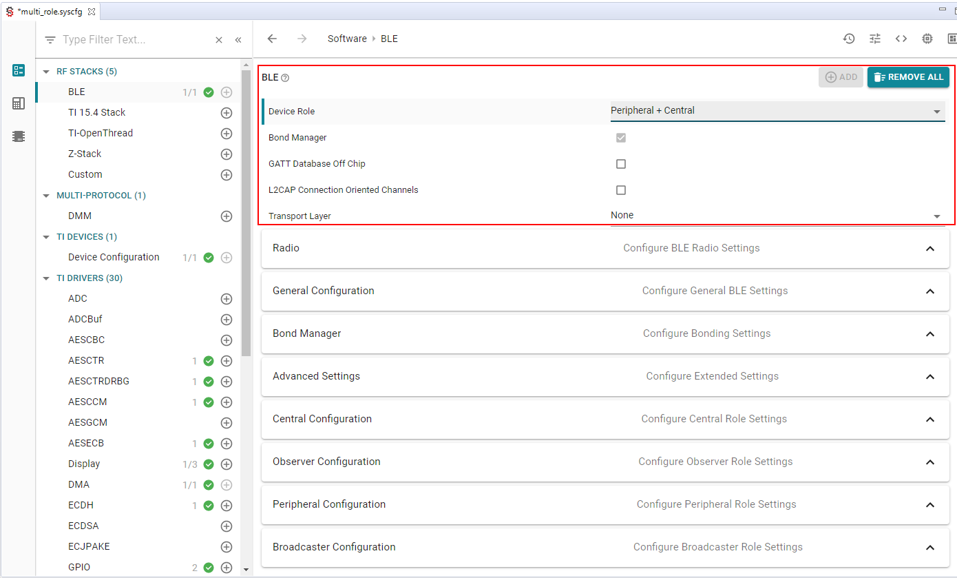
Figure 204. First Options
The Device Role configurable is an example of a drop down list where
you can select the specific Device Role you wish to use. Device Role
refers to the GAP Roles that the project operates as. This can be seen
in Figure 205. There are many different options with
different input methods available.
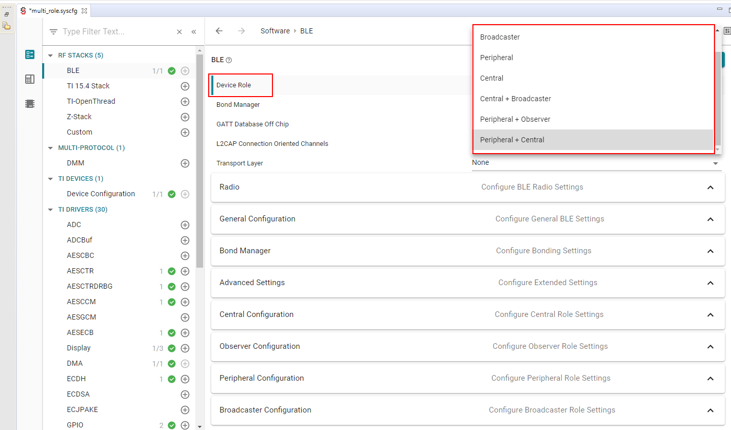
Figure 205. Device Role
When you first open a SysConfig project all of the settings for that project will be at their default values that are known to work with that example. Providing this amount of quick and easy configuration for a project is powerful. However, as we know, with great power comes great responsibility. Any one specific example is not guaranteed to function properly with any and all permutations of the available configurable options. More specifically, BLE5-Stack projects are written to implement one (or more) specific Generic Access Profile (GAP) Role Combinations, so one should not switch this unless you know what you’re doing. As long as the files that are generated from your input compile, the project will build. Whether or not it performs to the same degree depends on what you changed the options to.
Furthermore, the options that are available to modify will depend on the
GAP Roles that have been selected. Changing the Device Role may
add or remove options below it. If changing the Device Role option is
required, it is suggested to change this first so that you do not lose any work
you have already done below.
Open the SysConfig output (see Viewing SysConfig Output). After selecting a file you will be able, in real-time, to identify how the changes in the GUI effect the generated files. This will help you review the relationship between the GUI and the code.
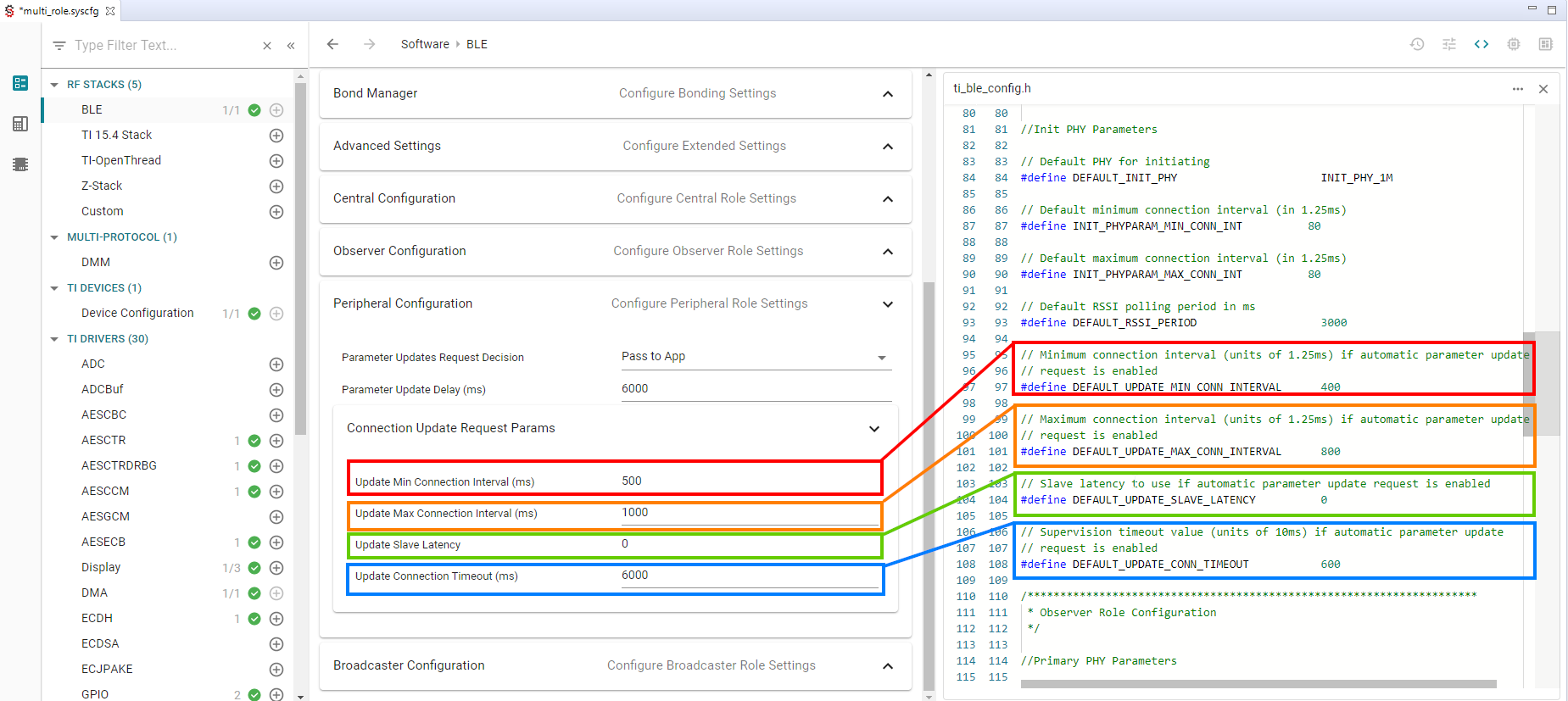
Figure 206. Code Review
Note
Changes will appear as a diff in the code view. Changes will be applied when the project is rebuilt.
Additional Configuration Categories
Note
Remember that the following Configuration Categories will depend on the
Role Combination (GAP Roles) you’ve chosen. Change
Role Combination before changing any of the below options.
Radio
In this view you can configure the front end mode, the bias configuration and the default TX Power. When relevant (i.e. for CC1352P devices), you can select on which RF design your project is based. For CC26x2 and CC1352R devices only one option is available and selected by default.
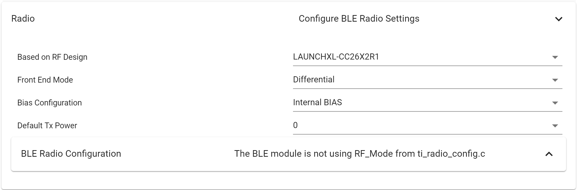
Figure 207. Radio
In Radio you will also find the BLE Radio Configuration view. Some of the
configurations made in BLE Radio Configuration Settings will show up in the
generated ti_radio_config files and are not applicable for BLE projects. The
Other Dependencies -> RF options control arguments in the RF Driver and
the Power Driver config in the Board.c file. For normal operation they should be
left unchanged.
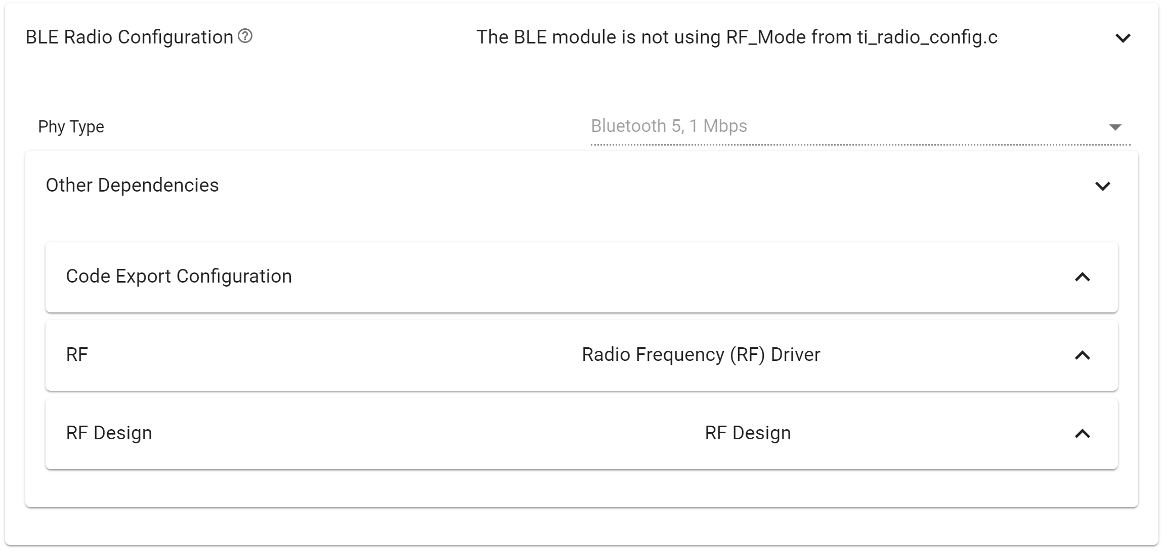
Figure 208. Radio - BLE Radio Configuration
In BLE Configuration, you will find the RF view. The RF view can be used to select pins for custom antenna switching. The RF view can be also used to enable RF coexistence feature. A few remarks regarding the code generated by SysConfig:
- When required, SysConfig will generate callback functions accordingly to the functionalities activated.
- The callback functions are generated in
ti_drivers_config.c.- Callback functions are only generated if user defined function name is valid (more than 0 characters, valid C identifier and not “NULL”).
- All “sub-callback” used in the global callback functions are declared ‘weak’ for application to override.
- Callback function with user defined name acts as a template, with description on how to create a new callback function, and how to filter on triggering events.
- Callback function for antenna switching changes function body if custom antenna switching is enabled.
- The antenna switching callback function’s code describes, with examples, how to handle pin interaction. It also contains function call to non-existing function with descriptive name, to attract attention at linker time and highlight that a new (‘strong’) definition of the function is required.
- The coexistence (coex) feature, when enabled, will also provide a callback function to handle the signaling specifics of the feature. Please see Configuration Options, which describes the coex options you can configure with SysConfig.
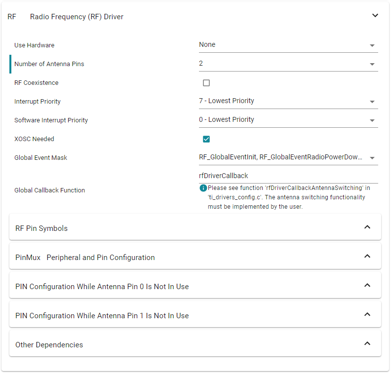
Figure 209. Radio - BLE Radio Configuration - RF
Advanced Settings
In this category you will find settings that configure the application such as Power Management and Two Button Menu options. You can also configure whether to use RCOSC and/or PTM mode. You will also find ICall options. More information:
- Power Management
- HAL Assert Handling
- Stack Library Configuration
- Extended Stack Settings, see 32 Connections Design
- GAPBondMgr and SNV
- RCOSC: See Running Bluetooth Low Energy on CC2640 Without 32 kHz Crystal
- Production and Direct Test Mode (PTM, DTM)
- ICall, see: Creating Additional ICall Enabled Tasks
Bond Manager Configurations
These settings control all the bond manager parameters and generate the function
setBondManagerParameters() in ble_config.c. This function sets all the bond
manager parameters as configured by SysConfig, and should be called from the
main application.
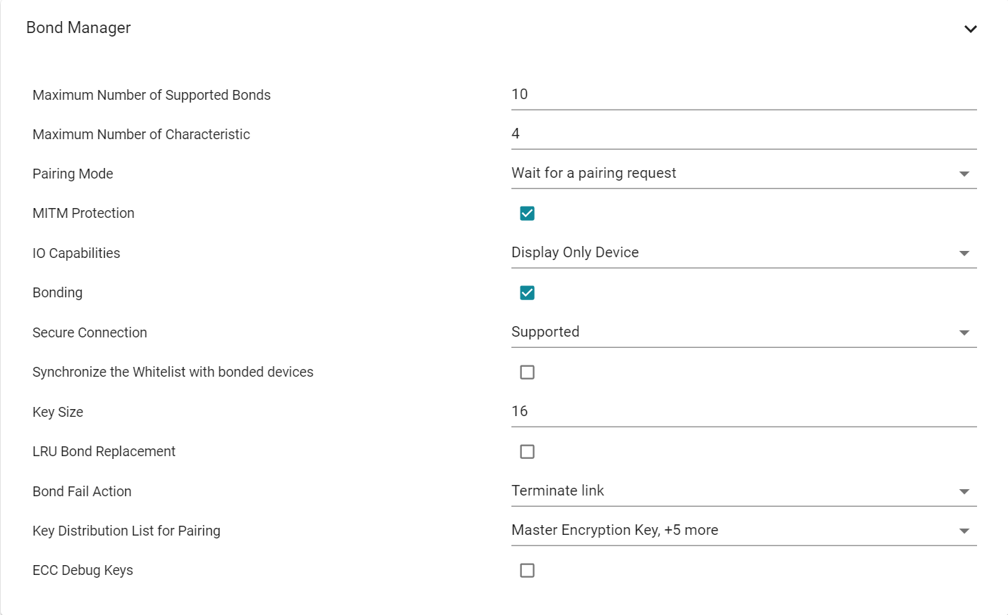
Figure 211. Bond Manager Configurations
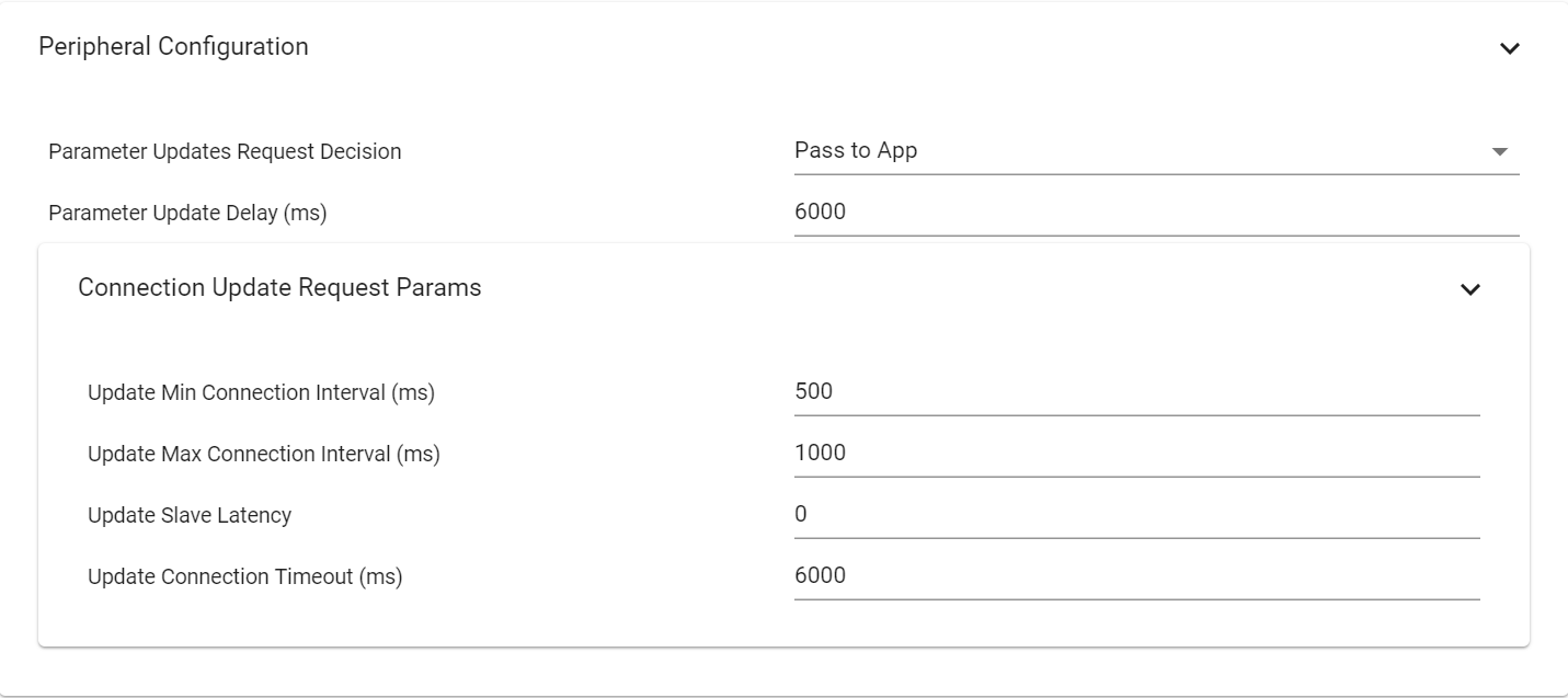
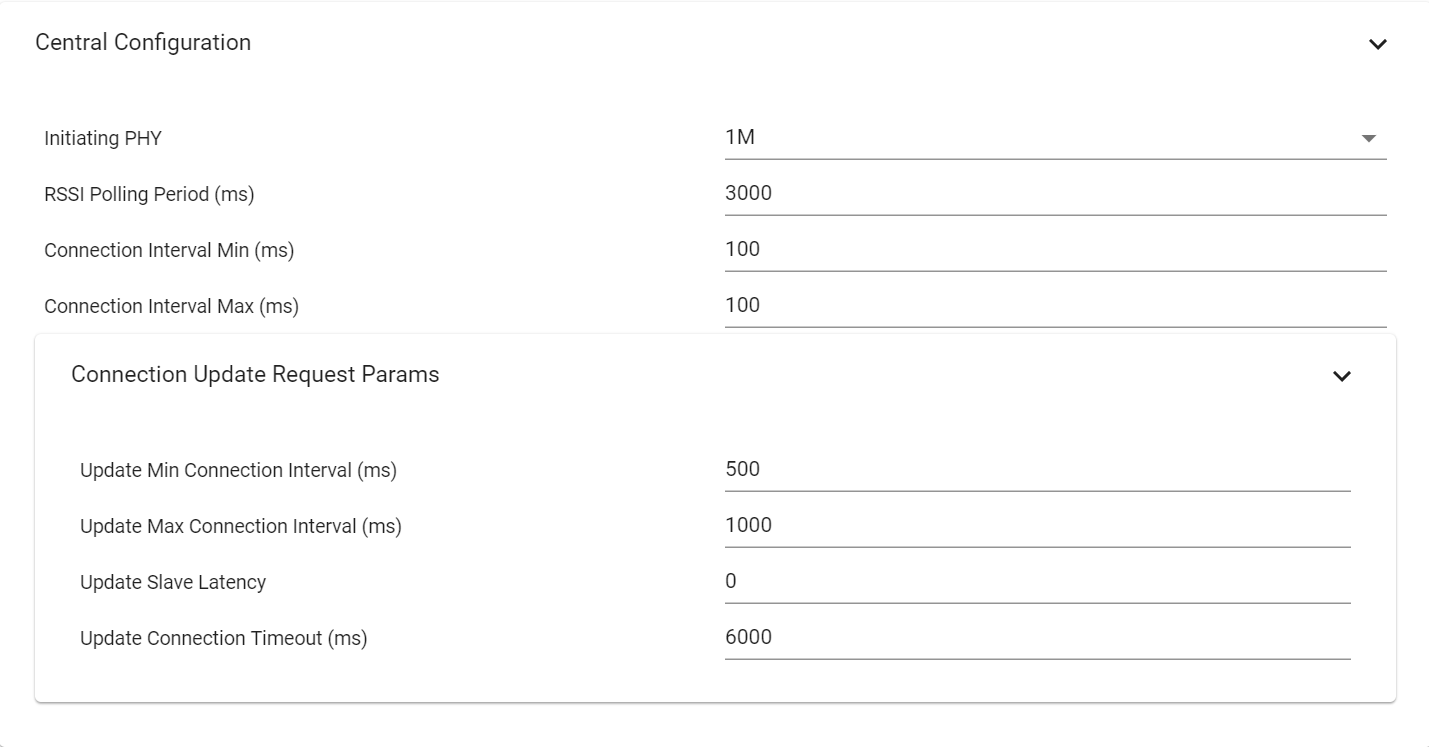
Broadcaster Configuration
- GAP Roles
- Advertisements
- For each advertisement set, the advertisement parameters (Advertisment Type, Channels, TX Power…), the advertisement data and the scan response can be set. The TX Power parameter will not affect Legacy Advertisement sets.
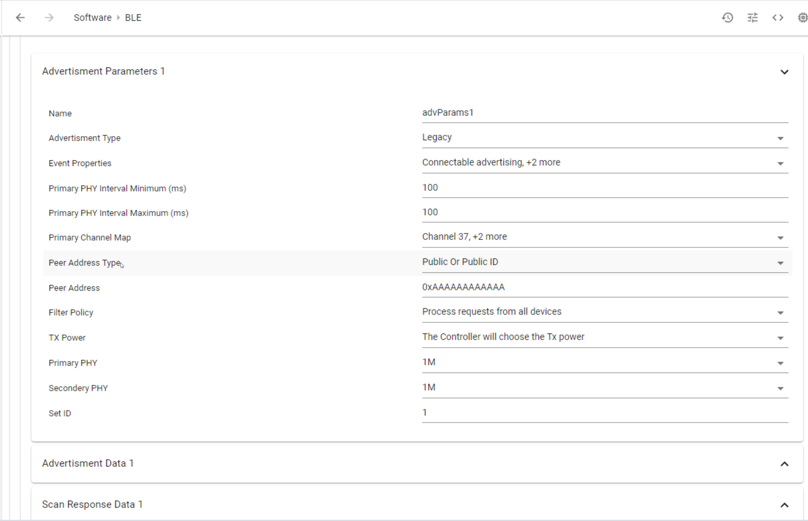
Figure 213. Broadcaster Configurations