3. Board/EVM Abstration
3.1. Board Support
3.1.1. Introduction
Board library contains a set of general initialization and setup functions that are board-specific. This component includes libraries for boards supported in the Processor SDK release. Refer to the package content for the list of supported boards.Board component also includes diagnostic software. Refer to Processor SDK RTOS DIAG for additional details on available diagnostic examples.
3.1.1.1. Board APIs
The Board_init() API supports initialization of PLL, peripheral clocks, external DDR memory, pinmux and IO Delay configurations. API Reference for application:
#. include <ti/board/board.h>
Example API pseudo code for Board_init() is as follows:
/* Setting up for pinmux and uart */
Board_STATUS ret;
Board_initCfg boardCfg;

boardCfg = BOARD_INIT_MODULE_CLOCK \| BOARD_INIT_PINMUX_CONFIG \|
BOARD_INIT_UART_STDIO;

ret = Board_init(boardCfg);
3.1.1.2. LLD Dependencies
3.1.1.2.1. I2C
Application need to configure BOARD_INIT_MODULE_CLOCK option to have I2C operational. I2C is used to read EEPROM data. An I2C handle will be opened in polling mode, and closed after the board ID data is retrieved from EEPROM using Board_getIDInfo() API.
For DRA7xx EVMs, I2C is also used to configure various I/O expanders and board muxes to enable PDK examples to function properly on the EVM. The I2C handles are opened in polling mode and closed after the board mux initialization has completed.
3.1.1.2.2. UART
Application need to configure Board_init() with the BOARD_INIT_UART_STDIO option to use the UART stdio API.
After Board_init() completes, application can invoke UART stdio functions such as UART_printf, UART_scanFmt, and etc.
3.1.2. Application Integration for AM5x/DRA7xx
When configuring pinmux with IO Delay settings for AM5x and DRA7xx boards, there is a hard restriction: the code/data/stack during the IO Delay setup must be within local internal memory. Refer to SOC TRM for additional information.
The board library specifies two sections for users to define for the sole purpose of meeting this requirement. They are: BOARD_IO_DELAY_CODE and BOARD_IO_DELAY_DATA. Below are examples of how to specify these section into the local memory, OCMC_RAM1:
In baremetal case with a linker cmd file:
BOARD_IO_DELAY_CODE : {

   . = ALIGN(4);
   *(BOARD_IO_DELAY_CODE*)

} > OCMC_RAM1

BOARD_IO_DELAY_DATA : {

   . = ALIGN(4);
   *(BOARD_IO_DELAY_DATA*)

} > OCMC_RAM1
In a CCS RTSC project with .cfg file:
Program.sectMap["BOARD_IO_DELAY_DATA"] = "OCMC_RAM1";
Program.sectMap["BOARD_IO_DELAY_CODE"] = "OCMC_RAM1";
3.1.2.1. Considerations for DRA7xx devices
When integrating the board library in applcations on DRA7xx, these code/data sections will likely overlap and conflict with the code/data sections used by the Secondary Boot Loader (SBL) as both modules will assume full access to OCMC_RAM1. Also, as the SBL performs identical configuration using the common pad config data structures, the pinmux request made by an application will be redundant. Therefore, it is advised that the pinmux API be used only when loading the application via CCS. When loading via SBL, there are three options available for handling this conflict:
- Place the BOARD_IO_DELAY_DATA/BOARD_IO_DELAY_CODE sections to another internal memory location. The Board library will check to see if the board code/data/stack are located in internal memory before executing the sequence. If another internal memory section is available for placement (e.g. L2SRAM, OCMC_RAM2), then it is acceptable to place the sections in these locations. The Board init sequence will proceed as expected.
- Place the BOARD_IO_DELAY_DATA/BOARD_IO_DELAY_CODE sections into external memory. The pinmux subroutine in the Board library checks for code/data/stack placement and will fail if it detects that they reside in DDR and return before performing the configuration. The failure will not affect any other Board init requests as other flags are treated orthogonally.
- Remove the BOARD_IO_DELAY_DATA/BOARD_IO_DELAY_CODE sections. This is
the preferred solution as it removes redundant code from executing
and will optimize code/data size and load speed. In order to remove
these sections, two modifications are required:
- Place BOARD_IO_DELAY_DATA/BOARD_IO_DELAY_CODE input sections into an output Dummy Section (DSECT). DSECTs are a Special Linker Section Type which are relocated for linker resolution but otherwise do not allocate space to a memory map, place sections in the output file, or ever get loaded to the target. In order to place these sections into DSECTS, modify the placement as follows:
Replace:
Program.sectMap["BOARD_IO_DELAY_DATA"] =
"OCMC_RAM1"; Program.sectMap["BOARD_IO_DELAY_CODE"] = "OCMC_RAM1";
With:
Program.sectMap["BOARD_IO_DELAY_DATA"] = new
Program.SectionSpec(); Program.sectMap["BOARD_IO_DELAY_CODE"] = new
Program.SectionSpec(); Program.sectMap["BOARD_IO_DELAY_DATA"].type =
"DSECT"; Program.sectMap["BOARD_IO_DELAY_CODE"].type = "DSECT";
- Remove the BOARD_INIT_PINMUX_CONFIG flag from the call to Board_init. Since the BOARD_IO_DELAY_DATA/BOARD_IO_DELAY_CODE sections no longer actually exist, we must instruct the application that it is no longer safe to call the routines and access the data. Otherwise, the CPU will branch to and access undefined memory and cause various exceptions
3.1.3. Custom Board Addition
Creating a custom board library has its merits whether you are creating it for custom silicon or for debugging/enhancements without losing your default board code. Below section include details needed for creation of additional board support.
3.1.3.1. Pinmux and IO Delay
When the BOARD_INIT_PINMUX_CONFIG option is specified, the Board_init() API configures the pinmux for the board. If applicable, it will also configure IO delay values for those device pads, which ensures correct IO timings are met along with the pinmux settings. Refer SOC TRM for additional details.
The pinmux data to be configured is generated by the TI pinmux tool. Refer to TI PinMux Tool for more information. For DRA7xx device, pinmux data is generated by the TI Pad Config Tool (PCT). Please contact TI for more assistance in obtaining this tool. Otherwise, values can be found through the device Data Manual (DM).
Note
Pinmux is needed for AM3/AM4/AM5/DRA7/K2G devices. Pinmux is not needed for C66x or K2H/K2E/K2L devices, and the BOARD_INIT_PINMUX_CONFIG option is ignored when called in a C66x or K2H/K2E/K2L board library.
3.1.3.2. Custom Board Library
- Set up your build environment according to the Building the RTOS SDK page.
- Create your own folder under the src directory. The name of this folder will be your board name (will be referred to as $BOARD). Put your source files in this src/$BOARD folder. Updated sources can also include initialization sequence for additional devices specific to board.
- Pinmux Update (see above note for applicable devices):
- Use the TI PinMux Tool to generate the new pinmux files. Refer the PinMux tool documentation on how to select pinmux for all the device pads and generate the pinmux data files.
- The four generated files are:
- boardPadDelay.h: Includes the prototypes of all structures and functions used by pinmux functions
- boardPadDelayInit.c: Includes the pinmux pad config data for all device pads along with values used to compute Manual/Virtual mode values.This data is used to configure pinmux during board initialization.
- boardPadDelayTune.h: This file includes the compile time macros used to select the Timing modes to be configured for modules during board Initialization.
- boardPadDelayDevice.c: This file includes the pinmuxdata for runtime pinmux configuration of the MMC module.
- Some platforms not requiring IO delay configurations will have two files <Platform Name>pinmux.h and <Platform Name>_pinmux_data.c files generated by the pinmux tool
- Copy the pinmux tool generated files to your custom board library implementation folder.
- Note: It is recommended to use the latest available PinMux Tool. For PinMux Tool prior to version v4.0.1482, you will have to edit boardPadDelayTune.h to select appropriate IO timing modes by uncommenting the build macros.
- SOC Clock Settings Update: The core clocks and module clocks used on the custom board library may vary based on the power requirements and external components used on the boards. TI provides Clock Tree Tools to simulate the device clocks. GEL file can be used to verify the settings in CCS before modifying the source in the board library.
- SOC DDR Configuration Update: The board library has the correct DDR initialization sequence to initialize the DDR memory on your board. You may need to make changes to the AC timings, hardware leveling, and DDR PHY configuration, some or all of which may be different than the TI supported platforms. GEL file can be used to verify the settings in CCS before modifying the source in the board library.
- IO Instance and Configuration update to Match Use Case: If your custom board uses an IO instance different from the TI-supported board, the instance needs to be modified in the Pin Mux setup as well as in the board_cfg.h file in pdk_xx_Xx_xx_xx/packages/ti/board/src/<customBoardName>/
- Updating the Files Corresponding to External Board Components: The custom board may have external components (flash devices, Ethernet PHY, etc.) that are different from the components populated on the TI-supported EVM. These components and their support files need to be added to the pdk_xx_Xx_xx_xx/packages/ti/board/src/<customBoardName>/device path and linked as part of the board library build.
- PLL Settings Update:
The SOC board library in the PDK configures the SOC PLL and module clock
settings to the nominal settings required to be used with the TI
evaluation platform. If you want to use different clock settings due to
power consideration, or if you are using a variant of the device that
needs to be clocked differently, you can enter the PLL and clock
settings in the board library. All of the PLL and module clock settings
are consolidated in the following files:
- <Board>.c: Contains calls related to all board-level initialization. <Board> refers to the evaluation platform (For example, evmam335x)
- <EVM>_pll.c: Defines the Board_PLLInit() function that configures the dividers and multipliers for the clock tree.
- <EVM>_clock.c: Defines clock dividers, scalars, and multipliers for individual board modules initialized using the board library.
- Create build makefile infrastructure for new board under <ti/board/build>. Please refer existing board makefiles for reference.
- Update top level makefile <ti/board/makefile> for additional support of new boards.
Adding custom board to the PDK directory structure and build setup is described in the article Adding Custom Board Library Target to Processor SDK RTOS makefiles
Note
TI evaluation platforms for Sitara Processors usually have board information stored in an EEPROM which checks for revision number and board name which is used to configure the board. When creating a custom platform if you don`t intend to use an EEPROM then we recommend removing code corresponding to Board_getIDInfo in your board library
3.2. Diagnostics
Overview
The Processor SDK RTOS Diagnostic package is designed to be a set of baremetal tests to run on a given board to provide data path continuity testing on peripherals. For K2H/K2E/K2L/C66x devices, this functionality is provided by POST.
Building the Examples
Pre-requisites to Building
- Set your environment using pdksetupenv.bat or pdksetupenv.sh. The diagnostic application uses the same environment variables as the board library build. Refer to the Processor SDK RTOS Building page for information on setting up your build environment.
- You will need the following libraries built:
- Board
- UART
- GPIO
- I2C
- SPI
- CSL
- ICSS
- PRUSS
(Note: not every library is used for every application, and these libraries should come pre-built with any fresh installation of the Processor SDK)
Compiling the Diagnostic Applications
To build the diagnostic examples:
- cd <PDK>/packages/ti/board/diag
- make <BOARD>
This will make the diagnostic applications for a specific $BOARD. Alternatively, “make all” will make for all boards. Output files will be located in: <PDK>/packages/ti/board/bin/<BOARD>
Creating the SD Card Loadable Files
For converting the compiled .out files to a format loadable by TI’s Secondary Boot Loader (SBL), you must follow these two steps:
- out2rprc.exe [.out file] [rprc output]
- MulticoreImageGen.exe LE 55 [output name] 0 [rprc output]
Out2rprc.exe and MulticoreImageGen.exe are tools supplied by TI and can be located in the <PDK>/packages/ti/boot/sbl/tools folder. “rprc output” can be any spare name of your choosing. “output name” can also be any name of your choosing. For diagnostic applications, your final output name must have the keyword “TEST” in it. You will have to do this process for every .out application you wish to be loadable on the SD card.
Alternatively, there is also a make target to automate this process:
- cd <PDK>/packages/ti/board/diag
- make <BOARD>_sd
This will compile all the applications for a specific $BOARD, and also create the SD card loadable files. The output files will be located in: <PDK>/packages/ti/board/bin/<BOARD>/sd. Note that the framework application is named “app” to allow it to be the default application to be loaded by the SBL.
Creating the SPI Flash Loadable Files
SPI boot shall be the primary boot option for the platforms (Ex: AMIC110 ICE) which does not support SD card interface. All the diagnostic tests are integrated into framework binary for the ease of use in the case of SPI boot. Integrated diagnostic framework test binary can be loaded and executed through UART port.
Use below command to build the diagnostic tests and create SPI flash loadable files.
- make <BOARD>_spi
Make targets
The simplest invocation is to use “make <BOARD>” to compile all the applications. Here is a list of make targets implemented for the diagnostic makefile:
- make <BOARD> - compile all diagnostic applications for one specific BOARD
- make clean - clean and remove all applications for all supported BOARDs
- make <BOARD>_clean - clean and remove all application for one specific BOARD
- make <BOARD>_sd - compile all diagnostic applications for one specific BOARD and create the SD card loadable files with those compiled applications
- make <BOARD>_spi - compile all diagnostic applications for one specific BOARD and create the SPI flash loadable files with those compiled applications
The <BOARD> supported depends on your Processor SDK RTOS variant. Refer to following table for available <BOARD> for each Processor SDK RTOS variant:
| make target / Variant | am335x | am437x | am57xx | k2g | omapl13x |
|---|---|---|---|---|---|
| <Board> | evmAM335x skAM335x bbbAM335x icev2AM33 5x iceAMIC11 0 | evmAM437x skAM437x idkAM437x | idkAM572x idkAM571x evmAM572x idkAM574x | evmK2G iceK2G | evmOMAPL1 37 (No Boot support. Diagnosti cs need to run from CCS) |
Note: OMAPL137 EVM diagnostic tests does not support executing from a boot device. Use the command make evmOMAPL137 to build the diagnostics. Diagnostics test binaries need to be executed from CCS.
Running the Diagnostic Examples
Loading through SD Card (Default Method)
Your SD card must be set up to a bootable format. Refer to the Processor SDK RTOS Boot page for information on how the SD card is handled.
You will need to compile the diagnostic applications for your BOARD, created their respective SD card loadable files, and copied them onto an SD card. You will also need the SBL (renamed to “MLO”) on the SD card. To do so:
- cd <PDK>/packages/ti/board/diag
- make <BOARD>_sd
- copy all the content under <PDK>/packages/ti/board/bin/<BOARD>/sd to your SD card
- copy the MLO to your SD card (default location at <PDK>/packages/ti/boot/sbl/binary/<BOARD>/mmcsd
- insert your SD card into your board and power on your board
- open Terminal emulator program eg: Teraterm to connect to the board’s UART console
- press the “Hard Reset” button on your board. (This is to force re-booting, and not absolutely necessary. Because Terminal emulator program is opened after boot is powered on, you would’ve missed the initial printout messages. This step is for demonstration and confidence checking that the board has booted correctly)
You should see the following screen:
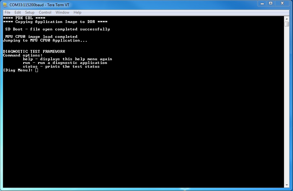
The framework diagnostic application should be loaded through SBL, and gives you the options:
- help - prints the command menu and descriptions of the commands
- run - run a diagnostic application found on the SD card
- status - current status of the framework run
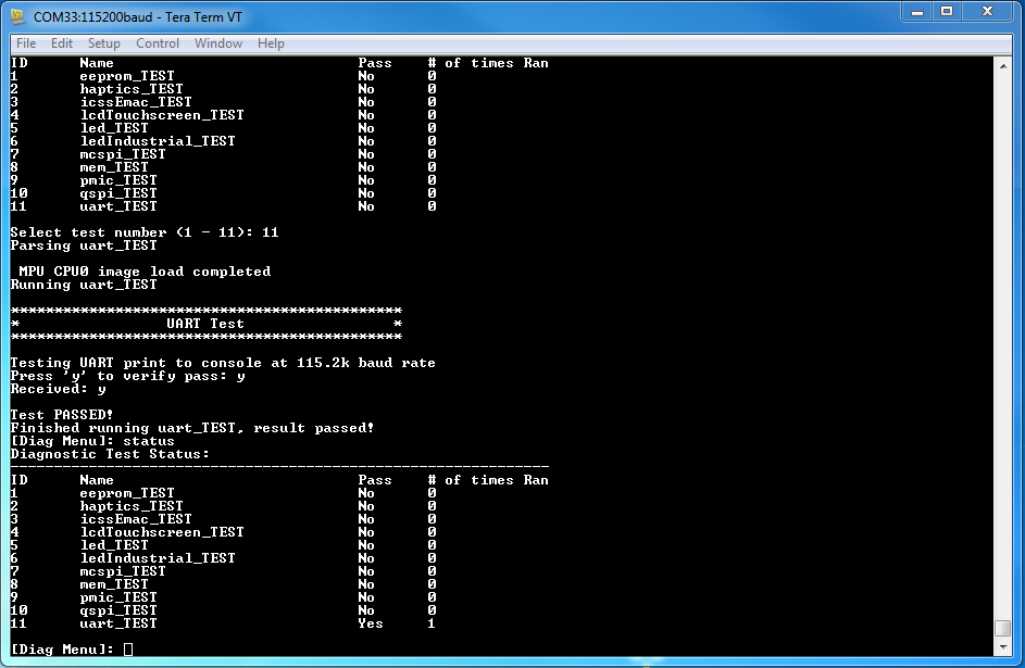
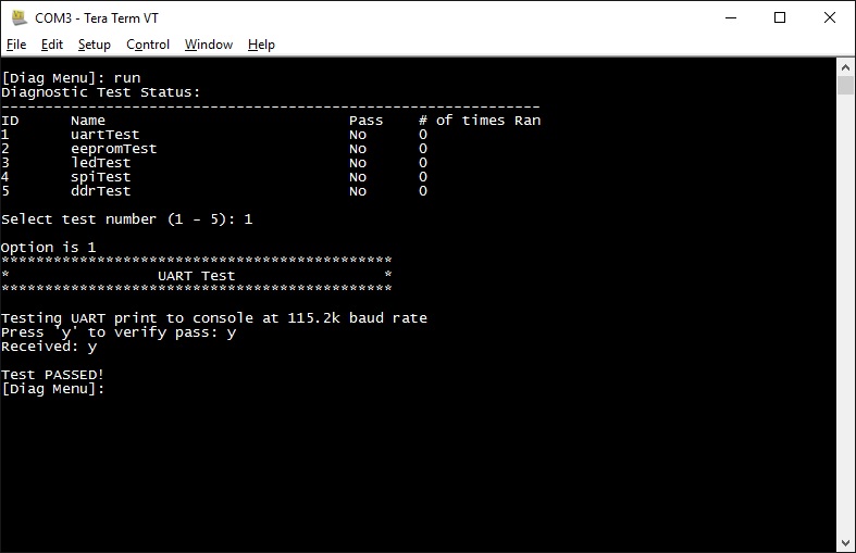
Below is an example of running a diagnostic application:
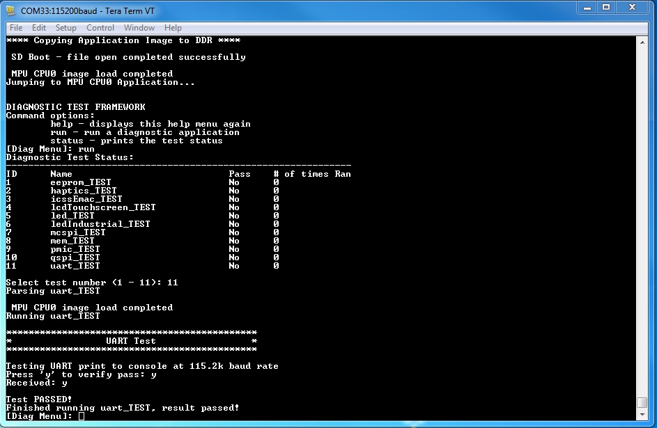
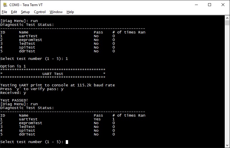
Result of return from above run:
Loading through SPI Flash
This section describes creating the diagnostic test images for SPI flash booting, programming and running them from SPI flash. Currently SPI boot is supported only by iceAMIC110 platform.
You will need to compile the diagnostic applications for your BOARD, create their respective SPI flash loadable files, and program them onto SPI flash. To do so:
- cd <PDK>/packages/ti/board/diag
- make <BOARD>_spi
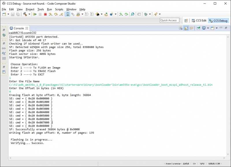
- Start CCS and launch target configuration file for AMIC110 ICE board
- Connect the target, load and run the SPI flash writer binary. Prebuilt SPI flash writer is available at <AM335x PDK>packagestistarterwaretoolsflash_writerspi_flash_writer_AM335X.out
- Choose option 1 to initiate image flashing
- Enter the file name as SPI bootloader along with full path (Ex: <AM335x PDK>packagestistarterwarebinarybootloaderbinam335x-evmgccbootloader_boot_mcspi_a8host_release_ti.bin)
- Enter offset as 0
- Wait until flashing completes successfully
- Rerun the SPI flash writer binary and program diagnostic framework loader at offset 20000. Diagnostic framework loader binary will be available at <AM335x PDK>packagestiboardbiniceAMIC110spiapp
- Rerun the SPI flash writer binary and program diagnostic framework at offset 40000. Diagnostic framework binary will be available at <AM335x PDK>packagestiboardbiniceAMIC110spiframework
Sample CCS output of SPI flash writer is shown below:
- open Terminal emulator program eg: Teraterm to connect to the board’s UART console
- press the “Hard Reset” button on your board. (This is to force re-booting, and not absolutely necessary. Because Terminal emulator program is opened after boot is powered on, you would’ve missed the initial printout messages. This step is for demonstration and confidence checking that the board has booted correctly)
You should see the following screen:
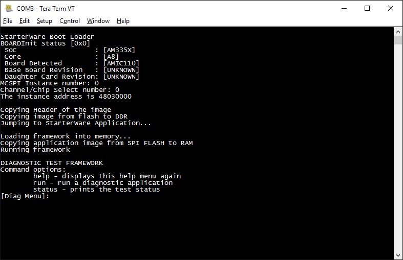
- help - prints the command menu and descriptions of the commands
- run - run a diagnostic application found on the SD card
- status - current status of the framework run
Below is an example of running a diagnostic application:
Running or debugging on CCS
To debug your application, CCS can give you access to the chip’s memory and register values. You can follow the below steps to load and run an application in CCS. If you have a SD card loadable image, and is able to load your application, you can connect to the A15 core in CCS and load symbols without having to load and run the entire application. After running “make all” or “make $BOARD”, the output files should be generated under <PDK>/packages/ti/board/bin/ directory. You will have to navigate down to the $BOARD you’re building (eg. idkAM572x, evmAM572x, etc.) and the $TARGET core you’re building for (eg. armv7).
For the existing diagnostic applications, you may need to define PDK_RAW_BOOT before compiling. This is done by adding the line “#define PDK_RAW_BOOT” to an individual application source file or to <PDK>/packages/ti/board/src/<BOARD>/include/board_cfg.h to apply for all applications. This is used because the default diagnostic loading method is through SD card, and the pinmux is done already. Adding this option only forces the diagnostic applications to do pinmuxing within the application itself (and not depend it being done).
To run on CCS:
- Connect USB cable to the board’s JTAG
- Connect the UART serial cable. For the IDK boards, the UART console is the same as the usb JTAG connector, so no additional cable is necessary.
- Plug in power cord to your board
- Press the power button on the board to turn the board on
- Setup and run CCSv6.1 (or higher). Follow the Processor SDK RTOS Getting Started Guide on how to setup your CCS to connect to the board
- Launch target configuration for the board
- Connect to the core that you built your application for. For example: for idkAM572x armv7 projects, click on the Cortex A-15 MPU0 core and press the connect button
- Load the program by pressing the load button and navigate the explorer to the .out file that you want to load
- Press the Run button to run the program
- Check UART console to see if anything is printed out. **If nothing is printed out, pause the core and see where the program counter is at. If it is at 0x3808c (or near it), try reloading the program and running again.
Note: On omapl13x platforms diagnostic tests can only be run from CCS as SBL support is not available at this point. Diagnostics are built for both DSP (C674x) and ARM (arm9) cores on omapl13x platform.
Running on a different ARM core
The diagnostic baremetal applications are typically targeted for Core 0 of an ARM corepac. It is possible to load and run it on one of the subcores in CCS. To do so, please consider the following:
- Enable Cache - setup typically only enables cache for the main ARM core. You may have to explicitly enable the data and instruction cache. See relevant cache functions under pdk/packages/ti/csl/arch.
- [For AM57x boards] Set OPP to high - SBL would set OPP to high for Core 0, but may not do it for the subcores. You can do so by using the GEL file. After connecting to the core, run the function under Scripts -> AM572x PRCM CLOCK configuration -> AM572x_PRCM_Clock_Config_OPPHIGH (similarly named for AM571x).
Diagnostic Applications
| Name | Description | GP AM572x | IDK AM572x/AM574x | IDK AM571x | EVM K2G | ICE K2G | EVM AM335x | SK AM335x | BBB AM335x | ICEv2 AM335x | EVM AM437x | SK AM437x | IDK AM437x | EVM OMAPL137 | ICE AMIC110 |
|---|---|---|---|---|---|---|---|---|---|---|---|---|---|---|---|
| lcdTouchscreen_diagExample_<BOARD>_armv7.out | Test for device detection and read the X, Y and Z axis values to confirm values within range. | x | x | x | x | ||||||||||
| adc_<BOARD>_armv7.out | Test for ADC configuration for Channel sequencing and One shot mode operation. | x | x | x | x | ||||||||||
| ambient_light_sensor_<BOARD>_armv7.out | Test for device detection on board and working of the light sensor. | x | x | ||||||||||||
| buzzer_diagExample_<BOARD>_armv7.out | Writes to GPIO in connected to a buzzer. Requires user to verify sound | x | x | ||||||||||||
| clock_generator_diagExample_<BOARD>_armv7.out | Probes the clock generator on I2C bus | x | |||||||||||||
| current_monitor_diagExample_<BOARD>_armv7.out | Read voltage current on I2C devices | x | |||||||||||||
| dcan_diagExample_<BOARD>_armv7.out | Does DCAN loopback writes and reads. Passes on successful return. | x | x | x | |||||||||||
| eeprom_diagExample_<BOARD>_armv7.out | Reads the EEPROM and prints out the board’s ID information. Passes on successful I2C reads. EEPROM will need to be programmed prior in order for a correct read. | x | x | x | x | x | x | x | x | x | x | x | x | x | |
| emac_diagExample_<BOARD>_armv7.out | Sends packet o PHY loopback t verify MAC operations | x | |||||||||||||
| emmc_diagExample_<BOARD>_armv7.out | Writes to and read from eMMC memory. Passes on reading back the correct value as the one written | x | x | x | x | ||||||||||
| framework_<BOARD>_armv7.out | The main diagnostic application. This is loaded by SBL and can load other diagnostic applications on the SD card. | x | x | x | x | x | x | x | x | x | x | x | x | x | |
| gmac_diagExample_<BOARD>_armv7.out | Sends and receive packets over ethernet, both internally and externally. Passes on receiving all packets. | x | x | ||||||||||||
| haptics_diagExample_<BOARD>_armv7.out | Writes to the GPIO pin connected to a motor (haptics). Requires user to verify that the motor is active. | x | x | x | |||||||||||
| hdmi_diagExample_<BOARD>_armv7.out | Tests HDMI display output | x | |||||||||||||
| icssEmac_diagExample_<BOARD>_armv7.out | Configures one ICSS EMAC port and tests functionality via packet loopback. | x | x | ||||||||||||
| ioexpGpio_diagExample_<BOARD>_armv7.out | Tests GPIO over the IO expander | x | |||||||||||||
| ioexpI2c_diagExample_<BOARD>_armv7.out | Tests I2C over the IO expander | x | |||||||||||||
| ioexpLed_diagExample_<BOARD>_armv7.out | Cycles through the LEDs on the IO expander | x | |||||||||||||
| lcd_diagExample_<BOARD>_armv7.out | Tests LCD display output | x | |||||||||||||
| lcdTouchscreen_diagExample_<BOARD>_armv7.out | Prompts the user for touches on the LCD touchscreen and report back its location. Requires user to input 9 simultaneous touches to verify pass. | x | x | ||||||||||||
| led_diagExample_<BOARD>_armv7.out | Cycles through GPIO LEDs on the board. Requires user to verify the LEDs blink. | x | x | x | x | x | x | x | x | x | x | x | x | x | |
| ledIndustrial_diagExample_<BOARD>_armv7.out | Cycles through the I2C LEDs on the board. Requires user to verify LEDs blink. | x | x | x | |||||||||||
| mcspi_diagExample_<BOARD>_armv7.out | Attempts one write and read on the MCSPI header. Requires user to verify the value being read back is as expected. | x | x | x | x | ||||||||||
| mem_diagExample_<BOARD>_armv7.out | Writes and reads to external (DDR) memory of the board. Value written/read is the address of the word. This is done two times, for value and ~value (complement), to test for all bits. | x | x | x | x | x | x | x | x | x | x | x | x | x | |
| mmcsd_diagExample_<BOARD>_armv7.out | Writes to and read from MMCSD memory. Passes on reading back the correct value as the one written | x | x | x | x | x | x | x | x | x | x | ||||
| nand_diagExample_<BOARD>_armv7.out | Tests reading and writing to NAND flash memory | x | |||||||||||||
| norflash_diagExample_<BOARD>_armv7.out | Tests reading and writing to NOR flash memory | x | |||||||||||||
| oled_display_diagExample_<BOARD>_armv7.out | Light up the OLED display to verify functionality | x | |||||||||||||
| pmic_diagExample_<BOARD>_armv7.out | Writes and reads to the PMIC controller. This is to verify ability to use I2C to control PMIC. Test passes on successful read and write. | x | x | x | x | x | x | x | x | x | |||||
| qspi_diagExample_<BOARD>_armv7.out | Tests the Quad SPI by writing and reading back the value written to memory. Test passes on correct data read back. | x | x | x | x | x | |||||||||
| rotary_switch_diagExample_<BOARD>_armv7.out | Tests the rotary switch at the 10 possible positions | x | |||||||||||||
| rtc_<BOARD>_armv7.out | Test for setting date and time to RTC registers and running the clock | x | x | x | x | x | x | x | |||||||
| temperature_diagExample_<BOARD>_armv7.out | Tests reading back from temperature sensor via I2C. Test passes on successful I2C reads. | x | x | x | x | ||||||||||
| uart2usb_diagExample<BOARD>_armv7.out | Tests uart messages over usb port. | x | |||||||||||||
| uart_diagExample_<BOARD>_armv7.out | Data Path continuity test for UART output. Requires user to verify that outputs do appear on console. | x | x | x | x | x | x | x | x | x | x | x | x | ||
| mcasp_diagExample_<BOARD>_<CORE>.out | On-board audio codec functionality is exercised by this test. Audio supplied at EVM audio input port will loopback to audio output port. This test is intended to demonstrate baremetal functionality of mcasp, edma3 and i2c CSL modules without depending on the LLD libraries. No console output is supported by this test. | x | x | ||||||||||||
| mcaspAudioDC_diagExample_<BOARD>_<CORE>.out | Multi-channel audio daughter card functionality is exercised by this test. Audio supplied at audio DC input ports will loopback to audio DC output ports. This test is intended to demonstrate bare metal functionality of mcasp, edma3 and spi CSL modules without depending on the LLD libraries. No console output is supported by this test. | x | |||||||||||||
| pwm_diagExample_<BOARD>_<CORE>.out | Demonstrates the usage of PWM CSL FL APIs by configuring the PWM module to generate a pulse of 1KHz with different duty cycle - 25, 50 and 75%. | x | x | x | x |
Additional Jumper or Hardware Settings
Current Monitor
For iceK2G, this test expects J16 and J17 to be connected with jumper shunts. This enables the current monitors to be used.
GMAC
For idkAM572x, idkAM571x, idkAM574x and evmAM572x, this test expects loopback plugs to be used on both Ethernet ports. These loopback plugs will loopback the TX lines back to the RX lines. The Ethernet ports are the RJ-45 connectors labeled “Ethernet” on the board.
ICSS EMAC
For idkAM572x, idkAM574x and idkAM571x, this test expects loopback plug to be used on J6. These loopback plugs will loopback the TX lines back to the RX lines. For iceK2G, this test expects loopback plugs to be used on all four ICSS EMAC ports.
LCD Touchscreen
For idkAM572x, idkAM574x and idkAM571x, this test expects the LCD module to be connected. This requires the two ribbon cables (one for display, one for the capacitive-touch IC) to be connected.
McSPI
For idkAM572x, idkAM574x and idkAM571x, this test expects pins to be connected to the Industrial I/O header. The Industrial I/O header, J37, has two columns in parallel, one of which is the McSPI input and the other being VDD. Thus, connecting any row with a jumper will yield a ‘1’ read on that McSPI input. By connecting the first, second, third, and forth row with jumpers would yield 0x1, 0x2, 0x4, and 0x8 being read respectively.
PWM
PWM output generated while running the diagnostic test can be verified at below pins.
evmK2G - J12 pin 33
evmAM572x - P17 pin 5
idkAM437x - J16 pin 14
evmAM335x - J5 pin 13
3.3. Power-On Self Test
Overview
The Power-On Self Test (POST) boot is designed to execute a series of platform/EVM factory tests on reset and indicate a PASS/FAIL condition using the LEDs and write test result to UART. A PASS result indicates that the EVM can be booted. POST is supported on K2H/K2E/K2L/C66x devices, this functionality is provided on other devices (e.g., AM57x) by Diagnostics.
POST will perform the following functional tests:
- External memory read/write test
- NAND read test
- NOR read test
- EEPROM read test
- UART write test
- LED test
Additionally, POST provides the following useful information:
- FPGA version
- Board serial number
- EFUSE MAC ID
- Indication of whether SA is available on SOC
- PLL Reset Type status register
Compilation
The recommended rule-of-thumb to compiling projects in the Processor SDK RTOS package is to use the makefiles provided. The makefiles are usable after setting up your shell/terminal/command prompt environment with the setupenv.bat or setupenv.sh script located in
[SDK Install Path]/processor_sdk_rtos_<platform>_<version>
Refer to Processor SDK RTOS Building the SDK guide on how to setup your environment for building within any of the Processor SDK RTOS packages.
To compile the POST application:
cd [SDK Install Path]/pdk_<platform>_<version>/packages/ti/boot/post/<platform>/build
make all
This will create the .out executable that can be loaded via CCS
Flashing POST Image
To flash a bootable image of POST, please refer to the SDK RTOS Flashing Bootable Images guide.
C66x LED Code
For C66x, the on-board LEDs can also provide diagnostic information on POST routines. Refer to the following table:
| Test Result | LED1 | LED2 | LED3 | LED4 |
|---|---|---|---|---|
| Test in progress | on | on | on | on |
| All tests passed | off | off | off | off |
| External memory test failed | blink | off | off | off |
| I2C EEPROM read failed | off | blink | off | off |
| EMIF16 NAND read failed | off | off | blink | off |
| SPI NOR read failed | off | off | off | blink |
| UART write failed | blink | blink | off | off |
| PLL initialization failed | off | off | blink | blink |
| NAND initialization failed | blink | blink | blink | off |
| NOR initialization failed | off | blink | blink | blink |
| EMAC loopback failed | on | blink | blink | blink |
| Other failures | blink | blink | blink | blink |
3.4. Board Utils
3.4.1. Uniflash
3.4.1.1. Overview
Uniflash is a standalone tool used to download application image over UART/JTAG serial interface and flash it on to the flash device on the target platform. This section explains on how to use Uniflash CLI tool to flash images to the TI’s MPU platform.
3.4.1.2. Supported Platforms
| SOC | PLATFORM | FLASH DEVICE | MODES | ||
|---|---|---|---|---|---|
| SPI | QSPI | UART | JTAG | ||
| AM335x | AM335x GP EVM | X | X | X | |
| AM335x ICEv2 | X | X | |||
| AMIC110 ICE | X | X | X | ||
| AM437x | AM437x IDK | X | X | ||
| AM571x | AM571x IDK | X | X | ||
| AM572x | AM572x IDK | X | X | ||
| AM574x | AM574x IDK | X | X | ||
| K2G | K2G GP EVM | X | X | ||
| K2G ICE | X | X | |||
where,
X - supported
3.4.1.3. Pre-Requisites
- Download and install the desktop version of Uniflash tool
2. Download and install the Processor-SDK RTOS package. See the software product page for your device to get the latest version of this software:
- Processor SDK for AM335x
- Processor SDK for AM437x
- Processor SDK for AM57xx
- Processor SDK for AMIC110
- Processor SDK RTOS for K2G
From the appropriate software product page, go to the download page by clicking “Get Software” for the RTOS package.
3.4.1.4. Binaries
Host
The dslite script file in Uniflash tool provides an option(- -mode) to execute the Uniflash CLI tool for TI’s MPU platforms.
The processors mode shall execute the Uniflash CLI binary to flash images to the TI’s MPU platforms. This mode will execute the Uniflash CLI binary <path_to_the_uniflash>/processors/ProcessorSDKSerialFlash.exe
Target
Get the Flash Writer binaries from <pdk_install_path>/packages/ti/board/utils/uniflash/bin/<board_name>/
Note
Flash Writer Binaries needs to be rebuilt for AM335x platform. Refer Rebuilding FlashWriter section to rebuild FlashWriter.
3.4.1.5. Display Help
Use the following command to display Help
For Windows
# cd <path_to_the_uniflash>
# dslite.bat --mode processors -h
For Linux
# cd <path_to_the_uniflash>
# sudo ./dslite.sh --mode processors -h
This will display help menu. Following is the sample output on Windows.
Executing the following command:
> C:\ti\uniflash_[Version Num]\processors\ProcessorSDKSerialFlash.exe -h

For more details and examples, please visit https://processors.wiki.ti.com/index.
php/UniFlash_[Version Num]_Quick_Guide#Command_Line_Interface


----------------------------------------------------------------------------
ProcessorSDKSerialFlash CLI Tool
Copyright (C) 2017-2018 Texas Instruments Incorporated - https://www.ti.com/
Version 0.2
----------------------------------------------------------------------------
Displaying Help..

Usage:
ProcessorSDKSerialFlash.exe -c <COM_Port> -f <Path_to_the_file_to_be_transfered>
 -d <Device_Type> -i <Image_Type> -e <erase_length -o <Offset>

Device_Type:
0 - NAND
1 - SPI
2 - QSPI

Image_Type:
0 - Flash
1 - MLO
2 - Uboot
3 - UImage
4 - Custom Inteface


erase_length:Length in Bytes


Note: File Path should not be specified in case of Flash Erase

Program Example:
ProcessorSDKSerialFlash.exe -c COM7 -f C:/Users/Documents/test.bin -d 0 -i 0 -o
20000

Erase Example:ProcessorSDKSerialFlash.exe -c COM7 -d 2 -e 1000 -o 20000
Note
Currently Image_Type(option -i) is not supported
3.4.1.6. Programming FlashWriter
Flash Writer binary is the target software, used to program the binaries on to the flash devices of the target platform.
There are two ways of loading and executing the Flash Writer on to the target platform:
- Loading Flash Writer via ROM boot (over UART interface), for the target platforms that support UART Boot mode
- Loading Flash Writer over JTAG interface, for the target platforms that do not support UART Boot mode
For the target platforms that support UART Boot mode, use the following procedure to transfer flash writer
Steps
- Set the sysboot pins in UART boot mode.
- Make sure the Serial connections between the Host PC and the target platform are established.
- Power cycle the board
- Issue the following commands on the Host PC
For Windows
# cd <path_to_the_uniflash>
# dslite.bat --mode processors -c <COM_Port> -f <Path_to_the_flash_writer_to_be_transfered>
Example:
# dslite.bat --mode processors -c COM1 -f C:\ti\pdk\ti\board\utils\uniflash\bin\uart_iceAMIC110_flash_programmer.bin
For Linux
# cd <path_to_the_uniflash>
# sudo ./dslite.sh --mode processors -c <COM_Port> -f <Path_to_the_flash_writer_to_be_transfered>
Example:
# sudo ./dslite.sh --mode processors -c /dev/ttyUSB1 -f /home/user/pdk/ti/board/utils/uniflash/bin/uart_iceAMIC110_flash_programmer.bin
The application will output the progress of file transfer on the Host PC. Following is the sample output on Windows.
Executing the following command:
> C:\ti\uniflash_[Version Num]\processors\ProcessorSDKSerialFlash.exe -c COM1 -f
C:\ti\pdk\ti\board\utils\uniflash\bin\uart_iceAMIC110_flash_programmer.bin

For more details and examples, please visit https://processors.wiki.ti.com/index.
php/UniFlash_[Version Num]_Quick_Guide#Command_Line_Interface


----------------------------------------------------------------------------
ProcessorSDKSerialFlash CLI Tool
Copyright (C) 2017-2018 Texas Instruments Incorporated - https://www.ti.com/
Version 0.2
----------------------------------------------------------------------------
Flashing Flash Writer to RBL..

Transferring File of size 56776 bytes
File Transfer complete!
Upon successful transfer, Flash Writer will be loaded and executed on the target platform. The Flash Writer starts sending character ‘C’(xmodem protocol). This can be verified on the serial console utility.
Note
Any Serial Console utility that supports xmodem protocol can be used. Verified utilities are Teraterm (in Windows) and Minicom (in Linux)
For the target platforms that does not support UART Boot mode, use the following procedure to load and execute flash writer over JTAG interface.
Steps
- Make sure the Serial and JTAG connections between the Host PC and the target platform are established.
- Power cycle the board
- Issue the following commands on the Host PC
For Windows
# cd <path_to_the_uniflash>
# dslite.bat --mode load --config=<Path_to_ccxml_file>
-f <Path_to_the_flash_writer_to_be_transfered> -n <core_to_be_connected_on_the_target_platform>
Example:
# dslite.bat --mode load --config=C:\Users\username\ti\CCSTargetConfigurations\iceAMIC110.ccxml -f C:\ti\pdk\packages\ti\board\utils\uniflash\bin\iceAMIC110\uart_iceAMIC110_flash_programmer.out -n 1
For Linux
# cd <path_to_the_uniflash>
# sudo ./dslite.sh --mode load --config=<Path_to_ccxml_file> -f <Path_to_the_flash_writer_to_be_transfered> -n <core_to_be_connected_on_the_target_platform>
Example:
# sudo ./dslite.sh --mode load --config=/home/ti/CCSTargetConfigurations/iceAMIC110.ccxml -f /home/user/pdk/ti/board/utils/uniflash/bin/uart_iceAMIC110_flash_programmer.out -n 1
The application will output the progress of file transfer on the Host PC Following is the sample output on Windows.
Executing the following command:
> "C:\ti\uniflash_[Version Num]\deskdb\content\TICloudAgent\win\ccs_base\DebugServer\bin\DSLite" load --config=C:\Users\username\ti\CCSTargetConfigurations\iceAMIC110.ccxml -f C:\ti\pdk\packages\ti\board\utils\uniflash\bin\iceAMIC110\uart_iceAMIC110_flash_programmer.out -n 1

For more details and examples, please visit https://processors.wiki.ti.com/index.php/UniFlash_[Version Num]_Quick_Guide#Command_Line_Interface

DSLite version [Version Num]
Configuring Debugger (may take a few minutes on first launch)...
        Initializing Register Database...
        Initializing: IcePick_D_0
        Executing Startup Scripts: IcePick_D_0
        Initializing: CS_DAP_M3
        Executing Startup Scripts: CS_DAP_M3
        Initializing: M3_wakeupSS_0
        Executing Startup Scripts: M3_wakeupSS_0
        Initializing: CS_DAP_DebugSS
        Executing Startup Scripts: CS_DAP_DebugSS
        Initializing: CortxA8
        Executing Startup Scripts: CortxA8
        Initializing: CSSTM_0
        Executing Startup Scripts: CSSTM_0
        Initializing: CSETB_0
        Executing Startup Scripts: CSETB_0
        Initializing: PRU_0
        Executing Startup Scripts: PRU_0
        Initializing: PRU_1
        Executing Startup Scripts: PRU_1
Connecting...
GEL: CortxA8: Output: ****  AM3359_ICE & BoosterPack Initialization is in progress ..........
GEL: CortxA8: Output: ****  AM335x & Booster Pack ALL PLL Config for OPP == OPP100 is in progress .........
GEL: CortxA8: Output: Input Clock Read from SYSBOOT[15:14]:  25MHz
GEL: CortxA8: Output: ****  Going to Bypass...
GEL: CortxA8: Output: ****  Bypassed, changing values...
GEL: CortxA8: Output: ****  Locking ARM PLL
GEL: CortxA8: Output: ****  Core Bypassed
GEL: CortxA8: Output: ****  Now locking Core...
GEL: CortxA8: Output: ****  Core locked
GEL: CortxA8: Output: ****  DDR DPLL Bypassed
GEL: CortxA8: Output: ****  DDR DPLL Locked
GEL: CortxA8: Output: ****  PER DPLL Bypassed
GEL: CortxA8: Output: ****  PER DPLL Locked
GEL: CortxA8: Output: ****  DISP PLL Config is in progress ..........
GEL: CortxA8: Output: ****  DISP PLL Config is DONE ..........
GEL: CortxA8: Output: ****  AM335x BoosterPack ALL ADPLL Config for 25 MHz OPP == OPP100 25MHz is Done .........
GEL: CortxA8: Output: ****  AM335x DDR3 EMIF and PHY configuration is in progress...
GEL: CortxA8: Output: EMIF PRCM is in progress .......
GEL: CortxA8: Output: EMIF PRCM Done
GEL: CortxA8: Output: DDR PHY Configuration in progress
GEL: CortxA8: Output: Waiting for VTP Ready .......
GEL: CortxA8: Output: VTP is Ready!
GEL: CortxA8: Output: DDR PHY CMD0 Register configuration is in progress .......
GEL: CortxA8: Output: DDR PHY CMD1 Register configuration is in progress .......
GEL: CortxA8: Output: DDR PHY CMD2 Register configuration is in progress .......
GEL: CortxA8: Output: DDR PHY DATA0 Register configuration is in progress .......
GEL: CortxA8: Output: DDR PHY DATA1 Register configuration is in progress .......
GEL: CortxA8: Output: Setting IO control registers.......
GEL: CortxA8: Output: EMIF Timing register configuration is in progress .......
GEL: CortxA8: Output: EMIF Timing register configuration is done .......
GEL: CortxA8: Output: PHY is READY!!
GEL: CortxA8: Output: DDR PHY Configuration done
GEL: CortxA8: GEL Output: Turning on EDMA...
GEL: CortxA8: GEL Output: EDMA is turned on...
GEL: CortxA8: Output: ****  AM3359_ICE Initialization is Done ******************


Loading Program: C:\ti\pdk\packages\ti\board\utils\uniflash\bin\iceAMIC110\uart_iceAMIC110_flash_programmer.out
        Preparing ...
        .text: 0 of 57716 at 0x402f0054
warning: CortxA8: Loader: One or more sections of your program falls into a memory region that is not writable.  These regions will not actually be written to the target.  Check your linker configuration and/or memory map.
        .text: 32752 of 57716 at 0x402f0054: 49%
        Finished: 49%
        Setting PC to entry point.: 49%
Running...
Success
The Flash Writer will be loaded and executed. The Flash Writer starts sending character ‘C’(xmodem protocol). This can be verified on the serial console utility.
3.4.1.7. Programming binaries to Flash Device
Follow the procedure explained in Section Programming FlashWriter to load Flash Writer binary to the target platform. Once the Flash Writer is loaded and executed, use the following commands to program binaries on to the Flash Device.
For Windows
# cd <path_to_the_uniflash>
# dslite.bat --mode processors -c <COM_Port> -f <Path_to_the_flash_writer_to_be_transfered> -d  <device_type> -o <offset>
Example:
# dslite.bat --mode processors -c COM7 -f C:\ti\pdk\packages\ti\starterware\binary\bootloader\bin\am335x-evm\gcc\bootloader_boot_mcspi_a8host_debug_ti.bin -d 1 -o 0x0
For Linux
# cd <path_to_the_uniflash>
# sudo ./dslite.sh --mode processors -c <COM_Port> -f <Path_to_the_flash_writer_to_be_transfered> -d  <device_type> -o <offset>
Example:
# sudo ./dslite.sh --mode processors -c /dev/ttyUSB1 -f /home/user/pdk/packages/ti/starterware/binary/bootloader/bin/am335x-evm/gcc/bootloader_boot_mcspi_a8host_debug_ti.bin -d 1 -o 0x0
where device type is,
- SPI Flash
- QSPI Flash
The application will output the progress of file transfer to the console on the Host PC. Following is the sample output on Windows.
Executing the following command:
> C:\ti\uniflash_[Version Num]\processors\ProcessorSDKSerialFlash.exe -c COM7 -f
C:\ti\pdk\packages\ti\starterware\binary\bootloader\bin\am335x-evm\gcc\bootloader_boot_mcspi_a8host_debug_ti.bin -d 1 -o 0x0

For more details and examples, please visit https://processors.wiki.ti.com/index.
php/UniFlash_[Version Num]_Quick_Guide#Command_Line_Interface


----------------------------------------------------------------------------
ProcessorSDKSerialFlash CLI Tool
Copyright (C) 2017-2018 Texas Instruments Incorporated - https://www.ti.com/
Version 0.2
----------------------------------------------------------------------------
Flashing Image to Flash Writer..

Transferring Header information..
Header Transfer complete!

Transferring File of size 55680 bytes
File Transfer complete!
Programming Flash Device..

Flash Programming Success!
3.4.1.8. Erasing Flash Device on the Target Platform
Follow the procedure explained in Section Programming FlashWriter to load Flash Writer binary to the target platform. Once the Flash Writer is loaded and executed, use the following commands to erase the Flash Device on the target platform
For Windows
# cd <path_to_the_uniflash>
# dslite.bat --mode processors -c <COM_Port> -e <Erase_Length_in_bytes> -d <device_type> -o <Erase_Offset>
Example:
# dslite.bat --mode processors -c COM7 -e 10000 -d 1 -o 20000
For Linux
# cd <path_to_the_uniflash>
# sudo ./dslite.sh --mode processors -c <COM_Port> -e <Erase_Length_in_bytes> -d <device_type> -o <Erase_Offset>
Example:
# sudo ./dslite.sh  --mode processors -c /dev/ttyUSB1 -e 10000 -d 1 -o 20000
The application will output the status to the console on the Host PC. Following is the sample output on Windows.
Executing the following command:
> C:\ti\uniflash_[Version Num]\processors\ProcessorSDKSerialFlash.exe -c COM7 -e 10000 -
d 1 -o 20000

For more details and examples, please visit https://processors.wiki.ti.com/index.
php/UniFlash_[Version Num]_Quick_Guide#Command_Line_Interface


----------------------------------------------------------------------------
ProcessorSDKSerialFlash CLI Tool
Copyright (C) 2017-2018 Texas Instruments Incorporated - https://www.ti.com/
Version 0.2
----------------------------------------------------------------------------
Erasing Flash....

Transferring Header information..
Header Transfer Complete!!
Flash Erase Success!
3.4.1.9. Rebuilding FlashWriter
- Use the following commands to rebuild Flash Writer
- For Windows
# cd <pdk_install_path>/packages
# pdksetupenv.bat
# cd ti\board\utils
# gmake clean
# gmake
- For Linux
# cd <pdk_install_path>/packages
# ./pdksetupenv.sh
# cd ti/board/utils
# make clean
# make
- Uniflash binaries will be created under the folder <pdk_install_path>/packages/ti/board/utils/uniflash/bin/<board_name>/
3.4.2. UART Apploader
UART AppLoader is a standalone application to download the application images over UART. Check the link UART AppLoader for more details on UART AppLoader.