4.3. PTP
4.3.1. Overview
The Precision Time Protocol (PTP), defined in IEEE 1588, is a protocol used to synchronize clocks throughout a network. Many applications in Industrial automation, Grid Infrastructure, Motion Control, AVB, and Telecom markets require nano-second accuracy/precision, varied update rates, rapid reconfiguration after network changes, fault tolerance. TI’s Sitara hardware platforms have dedicated hardware/firmware that help us meet these stringent requirements for synchronizing the distributed real-time clocks, in conjunction with LinuxPTP Application Stack. This page is specific to the PTP implementation in Linux, and the following sections provide details about the Software Architecture, Supported platforms, test setup and details about the support for Ordinary Clock (OC), Boundary Clock (BC) And Transparent Clock (TC)
Features supported
- PTP/1588
- PTP Slave and Master mode
- Supports P2P delay measurement
- Supports E2E delay measurement (GMAC only)
- PTP over IPv4 (Annex D) (GMAC only)
- PTP over 802.3 (Annex F)
- SAN Clock
- Ordinary Clock (GMAC/PRU port)
- Boundary Clock supported
- Two-step clock only
- DAN Clock
- Ordinary Clock (HSR/PRP port)
- Transparent clock as per IEC62439-3 Annex C
- Transparent clock one-step to two-step conversion (HSR node)
4.3.2. Software Overview
The picture below shows the Linux software stack of HSR/PRP/PTP in Processor SDK.
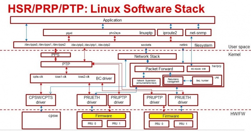
PTP is supported via the PRP firmware (in PRP EMAC mode) and Dual EMAC firmware.
4.3.2.1. Software Components
- PRUETH driver – Kernel driver abstracts PRU hardware/firmware
- PRUPTP driver – Kernel driver abstracts PRU-ICSS based PTP support
- CPTS driver - Kernel driver abstracts CPSW/CPTS based PTP support
- BC driver – Responsible for port state changes, IO Pad configuration
- HSR/PRP driver – Upstream HSR driver, with PRP support and additional bug fixes
- iproute2 - a collection of userspace utilities for controlling and monitoring various aspects of networking in the Linux kernel, including routing, network interfaces, tunnels, traffic control, and network-related device drivers
- net-snmp - a suite of software for using and deploying the SNMP protocol
- linuxptp (ptp4l, phc2sys)
- Filesystem (/dev/ppsX, /dev/ptpX)
4.3.2.2. linuxptp Overview
The Linux PTP Project is a software implementation of the PTP according to the IEEE 1588 Standard. This software is licensed under GNU GPL License, as described in the Processor SDK Software Manifest. For more details on Linux PTP framework and implementation refer: https://linuxptp.sourceforge.net/
LinuxPTP provides the four user applications - ptp4l, phc2sys, hwstamp_ctl and pmc. The definition and usage of these applications is as follows:
- ptp4l: It is the main program that implements the Precision Time Protocol (PTP) according to IEEE standard 1588 for Linux, as a Boundary Clock (BC) and Ordinary Clock (OC). The ‘slave’ and ‘master’ roles are determined for each port automatically using the BMC
- phc2sys: It is a utility program to synchronize the normal Linux system time to a PTP Hardware Clock - which itself is synchronized by the ptp4l program/application. For phc2sys, the terms ‘slave’ and ‘master’ are not about the PTP, but rather about two local clocks. Usually, the Linux system time is the slave, and the PHC is the master.
- pmc: This is a utility program for sending PTP management queries. The program reads from the standard input actions specified by name and management ID, sends them over the selected transport and prints any received replies.
- hwstamp_ctl: It is just a test program for the SIOCSHWTSTAMP ioctl, used for debugging. The ptp4l program does not need this program to function
TI has forked LinuxPTP to add support for Sitara family of devices, and the repo is hosted here: https://git.ti.com/processor-sdk/linuxptp
4.3.3. Hardware Overview
TI’s Sitara devices have support for GMAC and PRU-ICSS ports, as shown in the table below.
| SoC | # of GMAC ports | # of PRU-ICSS ports | PRU Firmware Supported |
|---|---|---|---|
| AM335x | 1 | 2(at 100Mbps) | Dual EMAC / HSR / PRP |
| AM437x | 1 | 2(at 100Mbps) | Dual EMAC / HSR / PRP |
| AM571x | 1 | 4(at 100Mbps) | Dual EMAC / HSR / PRP |
| AM572x | 1 | 2(at 100Mbps) | Dual EMAC / HSR / PRP |
| AM574x | 1 | 2(at 100Mbps) | Dual EMAC / HSR / PRP |
| K2G | 1 | 4(at 100Mbps) | Dual EMAC / HSR / PRP |
When using PTP as SAN port, only 1 port of each PRU-ICSS can independently support PTP at a time e.g. on AM571x, there are 4 PRU-ICSS ports, but only 1 from each of the 2 PRU-ICSS can be used as SAN PTP ports independently (as OC slaves) for a total of 2 ports since each PRU-ICSS functions as a single PTP clock entity.
4.3.3.1. GMAC
GMAC interface can be configured to run at either 100 Mbps or 1 Gbps. CPTS hardware block helps with timestamping of packets. Refer to here for details.
4.3.3.2. PRU-ICSS
The processing load is shared between firmware (PRU) and Host (ARM) with the firmware doing most of the time critical activities. The IEP hardware block in the PRU-ICSS sub-system is responsible for timestamping of packets. Memory map for the firmware interface for HSR/PRP firmware can be found in HSR/PRP Memory Map.
4.3.3.3. Hardware Modifications
- Hardware modifications are required on the AM57xx IDK platforms to provide access points to 1 PPS sync and latch signals for CPSW/CPTS and PRU-ICSS modules
- For Boundary Clock, since PPS generated by one internal clock needs to be latched into another internal clock, hardware, mainly blue wire, modifications are needed in order to achieive the latching of the PPS generated by one internal clock into another internal clock.
Please refer to AM571x-IDK modifications and AM572x-IDK/AM574x-IDK modifications documents and make the recommended changes to verify OC and BC, and to get access to 1 PPS signals
4.3.4. Generating 1 PPS
The PPS (Pulse Per Second) or 1PPS signal is an electrical signal that has a width of less than one second and a sharply rising or abruptly falling edge at the second boundary. The PPS signal can be used to measure the offset and jitters of the system time between the master and slave clock. This signal can also be used to synchronize the slave clock to its master within a BC.
4.3.4.1. Device Tree Setup
To enable PPS the device needs to first be booted using a different device tree file to enable the PPS pins, as listed below:
| SoC | Device Tree File (*.dtb) |
|---|---|
| AM335x | am335x-icev2-prueth-pps.dtb |
| AM437x | am437x-idk-pps.dtb |
| AM571x | am571x-idk-pps.dtb |
| AM572x | am572x-idk-pps.dtb |
| AM574x | am574x-idk-pps.dtb |
| K2G | keystone-k2g-ice-pps.dtb |
To configure this, change the device tree loaded in Uboot. If using the default Uboot environment, you can make the following changes to force the device to boot using the PPS device tree file.
1. Disable the automatic device tree file selection. Remove ‘run findfdt;’ from the relevant boot command (e.g. ‘bootcmd’, mmcboot’ or ‘netboot’)
2. Set the device tree file to be used.
setenv fdtfile <PPS dtb>
4.3.4.2. PRU-ICSS IEP
IEP has an additional hardware to generate a programmable sync output which is tied to the IEP counter. This is called the SYNC unit. For this signal generation CMP1 is programmed to a value of 1 second. A HIT event is generated by PRU0. Linux PRUETH IEP driver checks this event in and re-programs CMP1 after every hit to ensure that accurate sync pulses are generated. This sync is equivalent to the 1PPS output and should not be confused with PTP Sync frame.
To enable/disable 1PPS signal on PRU-ICSS port, enter the following commands respectively
echo 1 > /sys/devices/platform/pruss2_eth/ptp/ptp1/pps_enable
echo 0 > /sys/devices/platform/pruss2_eth/ptp/ptp1/pps_enable
or
echo 1 > /sys/devices/platform/pruss2_eth/ptp/ptp2/pps_enable
echo 0 > /sys/devices/platform/pruss2_eth/ptp/ptp2/pps_enable
echo 1 > /sys/devices/platform/pruss1_eth/ptp/ptp2/pps_enable
echo 0 > /sys/devices/platform/pruss1_eth/ptp/ptp2/pps_enable
or
echo 1 > /sys/devices/platform/pruss1_eth/ptp/ptp1/pps_enable
echo 0 > /sys/devices/platform/pruss1_eth/ptp/ptp1/pps_enable
Please note that both ptp1/2 may be assigned to pruss1(2)_eth based on the order of operations. Use the following command to find out the assigned PTP ports.
ls /sys/devices/platform/pruss1_eth/ptp
ls /sys/devices/platform/pruss2_eth/ptp
Note
Known Issue: On AM335x/AM437x, the current PPS implementation has the possibility of failing to correctly synchronize PPS output to a master (only the PPS output is affected, the PTP functionality still succeeds). This appears as the slave PPS being offset from the master PPS signal on an order of 40-100ms either on starting PPS or after running for an extended period of time. As a workaround, if PPS output is observed to be offset, then to temporarily stabilize PPS output for measurement, bring down and then bring back up the ethernet interface in use to reset PTP/PPS (e.g. ifconfig eth1 down/ifconfig eth1 up). If the PPS output is successful, then the output is valid and can be used to measure jitter.
4.3.4.3. GMAC
The GMAC/CPTS does not support a programmable sync output. Instead, the GP Timer16 can be programmed to generate an output pulse every 100ms or second and then this signal is passed to CPTS/HW_TS_PUSH4 to trigger the HW_TS_PUSH event. Linux CPSW/CPTS driver checks this event in and run through a simple algorithm to adjust the GP Timer reload value after every hit to ensure that output sync pulse is aligned at the second boundary of the PTP system time. In order to satisfy the +/-50ns jitter requirement by reducing the accumulation error, the current 1PPS implementation will generate a output pulse every 100ms and 9 out of 10 pulses will be filtered out except the one at the second boundary through the pad-config or GPIO-based output control.
To enable/disable 1PPS signal on GMAC/CPTS, enter the following command respectively:
echo 1 > /sys/devices/platform/44000000.ocp/48484000.ethernet/ptp/ptp0/pps_enable
echo 0 > /sys/devices/platform/44000000.ocp/48484000.ethernet/ptp/ptp0/pps_enable
4.3.4.4. PPS Output Latency Configuration
It should be possible to configure the latency of the 1PPS output of GMAC, PRU_ICSS to compensate for local propagation delay or for testing purpose. A new PTP interface has been defined and implemented to allow the PPS output latency to be adjusted in unit of ns.
The PPS output latency adjustment called PPS Offset can be set through the command interface or as the port configuration parameter of linuxptp.
To set PPS offset to -10ns on PRU-ICSS port, enter the following command:
echo -10 > /sys/devices/platform/pruss2_eth/ptp/ptp1/pps_offset
To set PPS offset to 10ns on GMAC/CPTS port, enter the following command:
echo 10 > /sys/devices/platform/44000000.ocp/48484000.ethernet/ptp/ptp0/pps_offset
To configure the PPS offset of eth2 to 20ns, add the following line to the OC/BC configuration file
[eth2]
ppsOffset 20
4.3.5. PTP Ordinary Clock
PTP ordinary clock (OC) is supported on both the CPSW GMAC ports and the PRU-ICSS ports.
The IEEE-1588-2009 standard defines ordinary clock as “A clock that has a single Precision Time Protocol (PTP) port in a domain and maintains the timescale used in the domain. It may serve as a source of time, i.e., be a master clock, or may synchronize to another clock, i.e., be a slave clock.”
At the heart of the ordinary clock support is the capability of being able to timestamp the PTP event messages that passes through the different Ethernet ports. It is the CPTS module that does the timestamping for the CPSW GMAC ports. For PRU-ICSS ports, it is the IEP module together with the PRU firmware that does the timestamping.
PHY Delay Compensation
The IEEE1588 timestamp should be measured at the Ethernet wire and therefore the ideal place to measure the egress/ingress timestamp of the Ethernet packets is at the Ethernet PHY. Unfortunately it is usually not the case. The delay between the actual timestamp location and the ideal location at the Ethernet wire will add to the path delay and create error of the path delay and offset of the system timestamp if the egress and ingress delay is not symmetric.
The Linux PTP software stack is designed to handle those delays with environment variable egressLatency and ingressLatency. Both delay number should be calculated or measured and used at the PTP configuration file. In the case that those two number are not available, use the following formulas to adjust those two variables as long as the measured path delay by Linux PTP is positive.
To reduce the 1PPS offset by x, increase the asymmetry delay compensation by 2x
To reduce the end-to-end delay by y, increase both ingressLatency and egressLatency by y.
4.3.5.1. PTP Ordinary Clock on PRU-ICSS
Timestamping of PTP event messages at the PRU-ICSS ports is provided by the PRU-ICSS IEP module together with the PRU firmware. PTP is supported via the Dual EMAC firmware, PRP firmware (configured in SAN (Single Attached Node). PTP with redundancy is supported via both HSR and PRP firmware.
In this Linux PRU-ICSS OC implementation, the PRU firmware stores timestamps (IEP counter values) of PTP event messages in specific shared memory locations. The PRU IEP driver retrieves the timestamps and converts them into PTP time values (in nanoseconds) before they are passed to upper layer for further processing. The current PRU-ICSS PTP clock frequency and time scale are kept in the IEP driver.
Since the PRU IEP drivers implements the Linux PTP hardware clock subsystem APIs, the PRU-ICSS PTP clock can therefore be adjusted by using those standard APIs. See PTP hardware clock infrastructure for Linux for more details.
The PTP OC protocol is provided by the linuxptp application.
If using PRP firmware for SAN, follow the steps at PRP EMAC mode to boot up the AM57xx IDK and configure the PRU-PRP firmware to run in PRP_EMAC mode (not needed if using Dual EMAC firmware). Once the AM57xx IDK is boot into Linux kernel prompt and the PRU-ICSS Ethernet ports are properly configured, to run linuxptp over the PRU-ICSS Ethernet ports, do
ptp4l -f oc.cfg
oc.cfg is a ptp4l configuration file.
Example oc.cfg for OC,
[global]
tx_timestamp_timeout 10
logMinPdelayReqInterval -3
logSyncInterval -3
twoStepFlag 1
summary_interval 0
[eth2]
egressLatency 726
ingressLatency 186
delay_mechanism P2P
network_transport L2
where eth2 is the intended PRU-ICSS Ethernet port over which the OC functionality is provided.
See The Linux PTP Project for more details about linuxptp in general and ptp4l(8) - Linux man page about ptp4l configurations in particular.
Here is a sample screen display of ptp4l for PRU-ICSS Ethernet port as PTP/OC in slave mode:
ptp4l -f oc.txt -s -m &
[1] 1153
root@am57xx-evm:~# ptp4l[3777.676]: selected /dev/ptp1 as PTP clock
ptp4l[3777.740]: port 1: INITIALIZING to LISTENING on INIT_COMPLETE
ptp4l[3777.743]: port 0: INITIALIZING to LISTENING on INIT_COMPLETE
ptp4l[3777.744]: port 1: received PDELAY_REQ without timestamp
ptp4l[3778.727]: port 1: new foreign master 8ca5a1.fffe.0000c2-1
ptp4l[3782.727]: selected best master clock 8ca5a1.fffe.0000c2
ptp4l[3782.727]: port 1: LISTENING to UNCALIBRATED on RS_SLAVE
ptp4l[3783.028]: port 1: UNCALIBRATED to SLAVE on MASTER_CLOCK_SELECTED
ptp4l[3783.653]: rms 756344481817248256 max 1512688963634496512 ( -31, 1512688963634496512) freq  +2319 +/- 877 delay    12 +/-   0
ptp4l[3784.653]: rms   28 max   32 ( -32,  -22) freq  +2612 +/-   9 delay    12 +/-   0
ptp4l[3785.778]: rms   16 max   24 ( -24,  -11) freq  +2604 +/-   3 delay    12 +/-   0
ptp4l[3786.778]: rms    6 max    9 (  -9,   -1) freq  +2607 +/-   3 delay    12 +/-   1
ptp4l[3787.904]: rms    3 max    6 (  -6,    4) freq  +2612 +/-   5 delay    12 +/-   0
ptp4l[3788.904]: rms    6 max   11 (   4,   11) freq  +2624 +/-   2 delay    12 +/-   0
ptp4l[3789.904]: rms    4 max    7 (  -2,    7) freq  +2621 +/-   5 delay    12 +/-   0
ptp4l[3790.904]: rms    5 max   10 ( -10,    2) freq  +2613 +/-   5 delay    11 +/-   0
ptp4l[3791.904]: rms    6 max   10 ( -10,    0) freq  +2606 +/-   4 delay    12 +/-   1
ptp4l[3792.904]: rms    3 max    6 (  -4,    6) freq  +2610 +/-   4 delay    11 +/-   1
ptp4l[3793.904]: rms    6 max   11 (   0,   11) freq  +2618 +/-   6 delay    12 +/-   0
ptp4l[3794.904]: rms    4 max    8 (  -5,    8) freq  +2618 +/-   5 delay    11 +/-   1
ptp4l[3796.029]: rms    3 max    6 (  -6,    4) freq  +2614 +/-   4 delay    12 +/-   1
ptp4l[3797.029]: rms    3 max    5 (  -5,    5) freq  +2614 +/-   4 delay    12 +/-   1
ptp4l[3798.030]: rms    2 max    4 (  -4,    3) freq  +2614 +/-   3 delay    12 +/-   0
ptp4l[3799.030]: rms    3 max    6 (  -4,    6) freq  +2616 +/-   4 delay    12 +/-   0
ptp4l[3800.030]: rms    3 max    5 (  -5,    5) freq  +2615 +/-   4 delay    10 +/-   0
ptp4l[3801.030]: rms    4 max    8 (  -8,    2) freq  +2609 +/-   5 delay    10 +/-   1
ptp4l[3802.030]: rms    7 max   12 ( -12,    3) freq  +2603 +/-   7 delay    11 +/-   0
ptp4l[3803.030]: rms    4 max    7 (  -7,    3) freq  +2601 +/-   4 delay    12 +/-   0
ptp4l[3804.030]: rms    4 max    7 (  -7,    4) freq  +2599 +/-   5 delay    13 +/-   1
ptp4l[3805.030]: rms    6 max    9 (  -8,    9) freq  +2600 +/-   8 delay    12 +/-   0
ptp4l[3806.030]: rms    5 max   10 (   0,   10) freq  +2609 +/-   4 delay    12 +/-   0
ptp4l[3807.030]: rms    5 max   10 ( -10,    6) freq  +2604 +/-   7 delay    12 +/-   0
ptp4l[3808.030]: rms    6 max    8 (  -8,   -1) freq  +2594 +/-   3 delay    11 +/-   0
ptp4l[3809.031]: rms    7 max   10 ( -10,   -2) freq  +2587 +/-   4 delay    12 +/-   1
ptp4l[3810.156]: rms    4 max    8 (  -8,    0) freq  +2587 +/-   4 delay    12 +/-   0
ptp4l[3811.156]: rms    2 max    4 (  -1,    4) freq  +2591 +/-   3 delay    12 +/-   1
ptp4l[3812.156]: rms    4 max    7 (  -2,    7) freq  +2596 +/-   4 delay    11 +/-   0
ptp4l[3813.406]: rms    3 max    6 (  -6,    1) freq  +2588 +/-   3 delay    12 +/-   0
ptp4l[3814.406]: rms    6 max    7 (  -7,    1) freq  +2582 +/-   5 delay    12 +/-   0
ptp4l[3815.406]: rms    4 max    7 (  -4,    7) freq  +2588 +/-   5 delay    11 +/-   0
ptp4l[3816.406]: rms    3 max    4 (  -4,    4) freq  +2587 +/-   4 delay    12 +/-   1
ptp4l[3817.531]: rms    4 max    6 (  -6,    6) freq  +2590 +/-   5 delay    12 +/-   1
ptp4l[3818.531]: rms    3 max    5 (  -5,    5) freq  +2587 +/-   4 delay    11 +/-   0
ptp4l[3819.532]: rms    4 max    5 (  -5,    4) freq  +2584 +/-   4 delay    12 +/-   0
ptp4l[3820.657]: rms    4 max    7 (  -1,    7) freq  +2592 +/-   3 delay    11 +/-   0
ptp4l[3821.782]: rms    4 max    9 (  -2,    9) freq  +2594 +/-   5 delay    11 +/-   0
ptp4l[3822.782]: rms    3 max    5 (  -5,    2) freq  +2589 +/-   4 delay    11 +/-   0
...
4.3.5.1.1. Redundancy (HSR/PRP)
To set up PTP OC over HSR/PRP redundant interface, first setup HSR/PRP interface as detailed in HSR/PRP Linux Software.
Start PTP with the same command listed above, but using a different configuration file: (where eth2/eth3 are the slave interfaces used for the HSR/PRP interface)
HSR:
[global]
sanity_freq_limit 0
step_threshold 0.00002
tx_timestamp_timeout 20

domainNumber 0
priority1    128
priority2    128
slaveOnly    0

twoStepFlag                  1
summary_interval             0
doubly_attached_clock        1

[hsr0]
redundancy                   1
delay_mechanism              P2P
network_transport            L2

[eth2]
redundancy                   1
redundancy_master_interface  hsr0
redundancy_slave_number      1

logAnnounceInterval          0
logSyncInterval              0
logMinPdelayReqInterval      0
announceReceiptTimeout       3
syncReceiptTimeout           2

delay_mechanism              P2P
network_transport            L2
egressLatency                726
ingressLatency               186
fault_reset_interval         0

[eth3]
redundancy                   1
redundancy_master_interface  hsr0
redundancy_slave_number      2

logAnnounceInterval          0
logSyncInterval              0
logMinPdelayReqInterval      0
announceReceiptTimeout       3
syncReceiptTimeout           2

delay_mechanism              P2P
network_transport            L2
egressLatency                726
ingressLatency               186
fault_reset_interval         0
PRP:
[global]
sanity_freq_limit            0
step_threshold               0.00002
tx_timestamp_timeout         10

domainNumber                 0
priority1                    128
priority2                    123
slaveOnly                    0

twoStepFlag                  1
summary_interval             0
doubly_attached_clock        1

[prp0]
redundancy                   2
delay_mechanism              P2P
network_transport            L2

[eth2]
redundancy                    2
redundancy_master_interface   prp0
redundancy_slave_number       1

logAnnounceInterval           0
logSyncInterval               0
logMinPdelayReqInterval       0
announceReceiptTimeout        3
syncReceiptTimeout            2

delay_mechanism               P2P
egressLatency                 726
ingressLatency                186
network_transport             L2
fault_reset_interval          0

[eth3]
redundancy                    2
redundancy_master_interface   prp0
redundancy_slave_number       2

logAnnounceInterval           0
logSyncInterval               0
logMinPdelayReqInterval       0
announceReceiptTimeout        3
syncReceiptTimeout            2

delay_mechanism               P2P
egressLatency                 726
ingressLatency                186
network_transport             L2
fault_reset_interval          0
4.3.5.1.2. VLAN
PTP can also operate over VLAN interfaces, which can either be standard ethernet or HSR/PRP VLAN interfaces. In both cases, the only change needed is to specify the VLAN interface as the PTP interface in the PTP config file. In the case of HSR/PRP VLAN, the HSR/PRP interface will be the VLAN enabled interface (not the slave interfaces) and is the only interface that would need to be changed in the config file. For example, in the above HSR/PRP PTP config files, the only change needed would to change “[hsr0]” or “[prp0]” to appropriate VLAN interfaces e.g. “[hsr0.2]” or “[prp0.2]”
4.3.5.1.3. Some useful commands
To see the availability of ICSS-PRU1 and ICSS-PRU2 on SoC:
root@am57xx-evm:~# ls /sys/devices/platform/
and look for pruss1_eth and/or pruss2_eth.
To see which interface is configured under, for example, ICSS-PRU2:
root@am57xx-evm:~# ls /sys/devices/platform/pruss2_eth/net
eth2/ eth3/
To see what is available under an ICSS-PRU ptp support:
root@am57xx-evm:~# ls /sys/devices/platform/pruss2_eth/ptp
ptp1/
root@am57xx-evm:~# ls /sys/devices/platform/pruss2_eth/ptp/ptp1
clock_name             fifo                   n_periodic_outputs     pps_available
dev                    max_adjustment         n_programmable_pins    pps_enable
device@                n_alarms               period                 subsystem@
extts_enable           n_external_timestamps  power/                 uevent
root@am57xx-evm:~# cat /sys/devices/platform/pruss1_eth/ptp/ptp2/clock_name
PRUSS1 timer
root@am57xx-evm:~# cat /sys/devices/platform/pruss2_eth/ptp/ptp1/pps_available
1
If ptp4l is started in the background and without the “-m” option to print any message to standard output, the system log file /var/log/messages can be used to get a glimpse of the progress of ptp4l. For example,
root@am57xx-evm:~# ptp4l -2 -P -f oc.cfg &
root@am57xx-evm:~#
root@am57xx-evm:~# tail -n 30 /var/log/messages
Dec  5 20:45:14 am57xx-evm daemon.info thttpd[946]:   fdwatch - 729 polls (0.2025/sec)
Dec  5 20:45:14 am57xx-evm daemon.info thttpd[946]:   timers - 3 allocated, 3 active, 0 free
Dec  5 20:58:06 am57xx-evm user.notice ptp4l: [83598.805] selected best master clock 70ff76.fffe.1c0f99
Dec  5 20:58:06 am57xx-evm user.notice ptp4l: [83598.805] port 2: MASTER to UNCALIBRATED on RS_SLAVE
Dec  5 20:58:06 am57xx-evm user.notice ptp4l: [83599.177] port 2: UNCALIBRATED to SLAVE on MASTER_CLOCK_SELECTED
Dec  5 20:58:06 am57xx-evm user.info ptp4l: [83599.427] rms 36120 max 72251 (-72251,    8) freq  -7075 +/-  88 delay     8 +/-  0
Dec  5 20:58:08 am57xx-evm user.info ptp4l: [83600.552] rms   15 max   19 (  11,   19) freq  -7141 +/-   8 delay     8 +/-   0
Dec  5 20:58:09 am57xx-evm user.info ptp4l: [83601.553] rms    8 max   13 (   1,   13) freq  -7139 +/-   5 delay     8 +/-   0
Dec  5 20:58:10 am57xx-evm user.info ptp4l: [83602.553] rms    3 max    4 (  -4,    4) freq  -7144 +/-   4 delay     7 +/-   0
Dec  5 20:58:11 am57xx-evm user.info ptp4l: [83603.553] rms    7 max   11 ( -11,   -4) freq  -7157 +/-   5 delay     8 +/-   0
Dec  5 20:58:12 am57xx-evm user.info ptp4l: [83604.554] rms    5 max   10 ( -10,    3) freq  -7159 +/-   5 delay     7 +/-   0
Dec  5 20:58:13 am57xx-evm user.info ptp4l: [83605.554] rms    2 max    4 (  -4,    2) freq  -7156 +/-   3 delay     7 +/-   0
Dec  5 20:58:14 am57xx-evm user.info ptp4l: [83606.680] rms    3 max    7 (  -7,    1) freq  -7160 +/-   3 delay     8 +/-   0
Dec  5 20:58:15 am57xx-evm user.info ptp4l: [83607.680] rms    5 max    9 (  -4,    9) freq  -7154 +/-   6 delay     8 +/-   0
Dec  5 20:58:16 am57xx-evm user.info ptp4l: [83608.680] rms    5 max    9 (   0,    9) freq  -7148 +/-   5 delay     7 +/-   0
Dec  5 20:58:17 am57xx-evm user.info ptp4l: [83609.681] rms    4 max    6 (  -4,    6) freq  -7149 +/-   5 delay     7 +/-   0
Dec  5 20:58:18 am57xx-evm user.info ptp4l: [83610.681] rms    2 max    4 (  -2,    4) freq  -7149 +/-   3 delay     7 +/-   0
Dec  5 20:58:19 am57xx-evm user.info ptp4l: [83611.806] rms    3 max    7 (  -7,    2) freq  -7151 +/-   4 delay     7 +/-   0
Dec  5 20:58:20 am57xx-evm user.info ptp4l: [83612.807] rms    2 max    4 (  -4,    4) freq  -7150 +/-   3 delay     8 +/-   0
Dec  5 20:58:21 am57xx-evm user.info ptp4l: [83613.807] rms    3 max    6 (  -2,    6) freq  -7148 +/-   4 delay     8 +/-   0
Dec  5 20:58:22 am57xx-evm user.info ptp4l: [83614.807] rms    5 max    9 (  -1,    9) freq  -7141 +/-   5 delay     8 +/-   0
Dec  5 20:58:23 am57xx-evm user.info ptp4l: [83615.808] rms    3 max    6 (  -4,    6) freq  -7143 +/-   4 delay     8 +/-   0
Dec  5 20:58:24 am57xx-evm user.info ptp4l: [83616.808] rms    2 max    5 (  -5,    1) freq  -7147 +/-   2 delay     7 +/-   0
Dec  5 20:58:25 am57xx-evm user.info ptp4l: [83617.934] rms    5 max    8 (  -8,    5) freq  -7150 +/-   7 delay     8 +/-   0
Dec  5 20:58:26 am57xx-evm user.info ptp4l: [83618.934] rms    3 max    5 (  -5,    3) freq  -7153 +/-   3 delay     8 +/-   0
Dec  5 20:58:27 am57xx-evm user.info ptp4l: [83619.934] rms    5 max    8 (  -1,    8) freq  -7145 +/-   5 delay     7 +/-   1
Dec  5 20:58:28 am57xx-evm user.info ptp4l: [83620.935] rms    6 max   10 (   2,   10) freq  -7136 +/-   2 delay     6 +/-   0
Dec  5 20:58:29 am57xx-evm user.info ptp4l: [83621.935] rms    4 max    7 (  -1,    7) freq  -7135 +/-   3 delay     8 +/-   1
Dec  5 20:58:30 am57xx-evm user.info ptp4l: [83622.935] rms    2 max    3 (  -1,    3) freq  -7136 +/-   2 delay     9 +/-   0
Dec  5 20:58:31 am57xx-evm user.info ptp4l: [83624.061] rms    4 max    6 (   0,    6) freq  -7131 +/-   3 delay     8 +/-   0
root@am57xx-evm:~#
4.3.5.1.4. PHY Delay Compensation for AM57xx IDK
The accuracy of PTP time provided by an OC depends in part on the accountability of the latencies introduced by the Ethernet of PHY and the timestamping point at which a PTP event message is timestamped.
IEEE-1588-2009 specifies that timestamp should be taken right after the SOF (start of frame). For Ethernet this is right after the SFD (start frame delimiter) or right before the destination MAC address. In the case of PRU-PRP firmware, only SOF timestampping is available for a TX PTP event message. And because in a 100 mbps line speed, 1 bit time is equivalent to 10ns, hence 640 ns ( (7 bytes preamble + 1 byte SFD) * 8 bits * 10ns) needs to be compensated in the TX direction.
Furthermore, the PRU-ICSS PHY TLK110 on AM57xx IDK introduces a latency of 86 ns in the TX and 186 ns in the RX direction.
Thus a total of 640 + 86 = 726 ns in the TX direction and 186 ns in the RX direction need to be accounted for.
When linuxptp’s ptp4l is used as the PTP protocol application, the following should be used for IngressLatency and EgressLatency configuration respectively.
| Speed | Egress Latency (ns) | Ingress Latency (ns) |
|---|---|---|
| 100Mb | 726 | 186 |
This also explains the two lines that corresponds to egressLatency and ingressLatency in the sample ptp4l configuration file oc.cfg in the ptp4l example above.
4.3.5.1.5. Limitations
Although there are two Ethernet ports available on each ICSS-PRU present, ICSS-PRU PTP OC can only be supported on at most ONE such port. It cannot provide PTP OC functionality on both Ethernet ports on the same ICSS-PRU simultaneously.
4.3.5.2. PTP Ordinary Clock on GMAC
Refer to here for more details about the CPTS driver and how to run linuxptp over the CPSW GMAC port for providing the PTP OC functionality.
For example, once the AM57xx IDK is boot into Linux kernel prompt and the CPSW GMAC ports are properly configured, to run linuxptp over the GMAC port, do
ptp4l -2 -P -f oc_eth1.cfg -s -m
oc_eth1.cfg is a ptp4l configuration file.
Example oc_eth1.cfg for OC,
[global]
tx_timestamp_timeout 10
logMinPdelayReqInterval -3
logSyncInterval -3
twoStepFlag 1
summary_interval 0
[et1]
egressLatency 146
ingressLatency 246
where eth1 is the intended GMAC port over which the OC functionality is provided.
Here is a sample screen display of ptp4l for GMAC port as PTP/OC in slave mode:
root@am57xx-evm:~# ptp4l -2 -P -f oc_eth1.txt -s -m &
[1] 1201
root@am57xx-evm:~# ptp4l[235215.373]: selected /dev/ptp0 as PTP clock
ptp4l[235215.461]: port 1: INITIALIZING to LISTENING on INITIALIZE
ptp4l[235215.462]: port 0: INITIALIZING to LISTENING on INITIALIZE
ptp4l[235215.463]: port 1: link up
ptp4l[235216.399]: port 1: new foreign master 8ca5a1.fffe.0000c2-1
ptp4l[235220.400]: selected best master clock 8ca5a1.fffe.0000c2
ptp4l[235220.400]: port 1: LISTENING to UNCALIBRATED on RS_SLAVE
ptp4l[235220.701]: port 1: UNCALIBRATED to SLAVE on MASTER_CLOCK_SELECTED
ptp4l[235221.451]: rms 3003 max 3986 (-3986, -1007) freq   -883 +/- 2090 delay    55 +/-   1
ptp4l[235222.451]: rms  562 max  873 (-612,  873) freq   +943 +/- 756 delay    54 +/-   1
ptp4l[235223.451]: rms  935 max  980 ( 838,  980) freq  +2627 +/- 243 delay    54 +/-   0
ptp4l[235224.451]: rms  593 max  787 ( 366,  787) freq  +2958 +/-  24 delay    54 +/-   0
ptp4l[235225.451]: rms  192 max  318 (  54,  318) freq  +2777 +/-  69 delay    54 +/-   0
ptp4l[235226.451]: rms   39 max   62 ( -62,   28) freq  +2572 +/-  50 delay    55 +/-   1
ptp4l[235227.451]: rms   60 max   68 ( -68,  -52) freq  +2468 +/-  13 delay    55 +/-   0
ptp4l[235228.452]: rms   36 max   46 ( -46,  -24) freq  +2451 +/-   4 delay    54 +/-   1
ptp4l[235229.452]: rms   11 max   17 ( -17,    4) freq  +2466 +/-   8 delay    53 +/-   0
ptp4l[235230.452]: rms    6 max   11 (   2,   11) freq  +2485 +/-   5 delay    54 +/-   0
ptp4l[235231.452]: rms   11 max   17 (   3,   17) freq  +2501 +/-   4 delay    54 +/-   0
ptp4l[235232.452]: rms    6 max    8 (  -6,    8) freq  +2496 +/-   7 delay    55 +/-   1
ptp4l[235233.452]: rms    3 max    4 (  -4,    4) freq  +2492 +/-   4 delay    56 +/-   0
ptp4l[235234.452]: rms    5 max    9 (  -7,    9) freq  +2492 +/-   7 delay    55 +/-   1
ptp4l[235235.452]: rms    7 max   10 ( -10,    1) freq  +2481 +/-   4 delay    55 +/-   1
ptp4l[235236.452]: rms    3 max    6 (  -6,    2) freq  +2482 +/-   4 delay    53 +/-   0
ptp4l[235237.452]: rms    5 max    8 (  -8,    3) freq  +2478 +/-   5 delay    54 +/-   0
ptp4l[235238.452]: rms    4 max    7 (  -7,    7) freq  +2482 +/-   6 delay    54 +/-   0
ptp4l[235239.453]: rms    5 max    9 (  -6,    9) freq  +2486 +/-   6 delay    54 +/-   0
ptp4l[235240.453]: rms    5 max    9 (  -9,    4) freq  +2480 +/-   6 delay    55 +/-   0
ptp4l[235241.453]: rms    5 max   10 ( -10,    4) freq  +2475 +/-   5 delay    56 +/-   0
ptp4l[235242.453]: rms    3 max    5 (  -1,    5) freq  +2483 +/-   3 delay    56 +/-   0
ptp4l[235243.453]: rms    2 max    4 (  -1,    4) freq  +2483 +/-   2 delay    56 +/-   0
ptp4l[235244.453]: rms    5 max   10 ( -10,   -1) freq  +2473 +/-   3 delay    55 +/-   0
ptp4l[235245.453]: rms    4 max    7 (  -6,    7) freq  +2479 +/-   5 delay    55 +/-   0
ptp4l[235246.453]: rms    5 max    9 (  -1,    9) freq  +2486 +/-   4 delay    54 +/-   1
ptp4l[235247.453]: rms    3 max    7 (  -7,    4) freq  +2483 +/-   5 delay    55 +/-   0
ptp4l[235248.453]: rms    6 max    9 (   2,    9) freq  +2492 +/-   4 delay    55 +/-   0
ptp4l[235249.453]: rms    4 max    7 (  -3,    7) freq  +2493 +/-   4 delay    57 +/-   0
ptp4l[235250.454]: rms    3 max    5 (  -5,    1) freq  +2486 +/-   3 delay    55 +/-   1
ptp4l[235251.454]: rms    8 max   16 ( -16,   -2) freq  +2476 +/-   7 delay    54 +/-   1
...
4.3.5.2.1. PHY Delay Compensation for AM57xx IDK
The theoretical values to use for GMAC PHY, which is KSZ9031RN, on AM57xx IDKs, are not yet available. The following experimental values are recommended for now.
| Speed | Egress Latency (ns) | Ingress Latency (ns) |
|---|---|---|
| 100Mb | 546 | 646 |
| 1000Mb | 146 | 346 |
4.3.5.3. Test Setup
Supported Platforms
- AM335x ICE (PRU-ICSS0:eth0-eth1)
- AM437x IDK (PRU-ICSS0:eth1-eth2)
- AM571x IDK (GMAC/CPTS: eth0-eth1, PRU-ICSS2:eth2-eth3,PRU-ICSS1:eth4-eth5)
- AM572x IDK (GMAC/CPTS: eth0-eth1, PRU-ICSS2:eth2-eth3)
- K2G ICE (PRU-ICSS2:eth1-eth2,PRU-ICSS1:eth3-eth4)
Hardware Modifications
Refer to the Hardware Modifications
Using 1 PPS to measure synchronization accuracy/offset
Some PTP test equipment and PTP-enabled Network adaptors provide 1PPS signal be used to measure the offset and jitters of the system time between the master and slave clock.
Test with Oregano Syn1588 Network Adaptor
The Oregano Syn1588 network adaptor [2]is configured to be the PTP master clock with the Linux PTP/Ethernet utilities.
Oregano Network Adaptor Configurations
Enter the regular ifconfig command to configure the desired IP address
#ifconfig enp4s0 192.168.3.20
Specify the network speed only if it is required, auto negotiation should be enabled for all other use cases
//Specify the Link Speed
#ethtool -s np4s0 speed 100 duplex half autoneg off
//enable auto negotiation
#ethtool -s nep4s0 autoneg on
To configure the Oregano Network Adaptor as a PTP/OC master clock, enter the following command
#./ptp -i enp4s0 -L -CM_EXT -s-3 -DP
PRU-ICSS Port Configurations
Follow the steps at PRP EMAC mode to boot up the AM57xx IDK and configure the PRU-PRP firmware to run in PRP_EMAC mode if using PRP firmware.
Use the ifconfig command to configure the desired IP address, for example
#ifconfig eth2 192.168.3.30
Verify the Ethernet connection by pinging the IP address of the master port
#ping 192.168.3.20
#ptp4l -2 -P -f oc_eth2.txt -s -m &
#echo 1 > /sys/devices/platform/pruss2_eth/ptp/ptp1/pps_enable
GMAC Port Configurations
Use the ifconfig command to configure the desired IP address, for example
#ifconfig eth1 192.168.3.40
#ping 192.168.3.20
#ptp4l -2 -P -f oc_eth1.txt -s -m &
#echo 1 > /sys/devices/platform/44000000.ocp/48484000.ethernet/ptp/ptp0/pps_enable
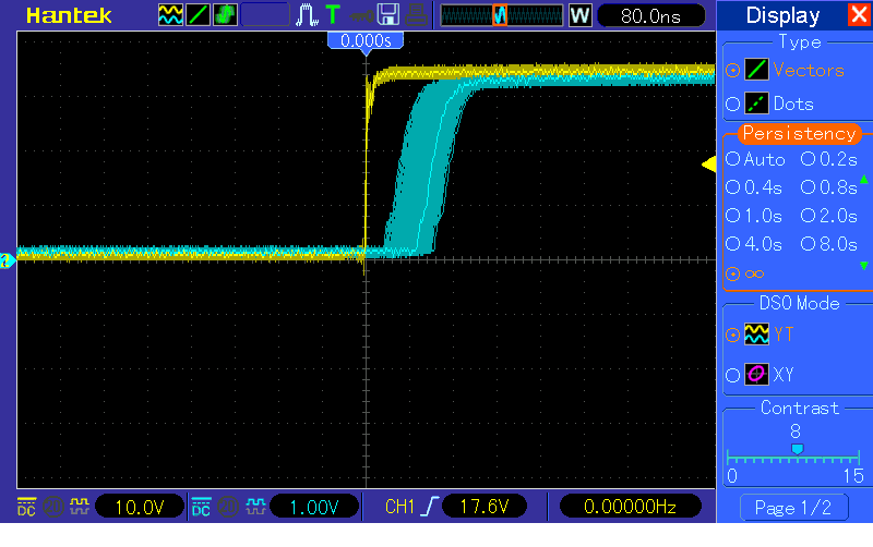
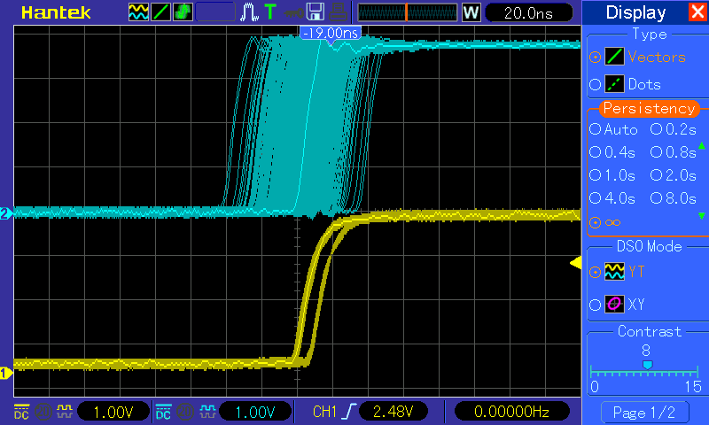
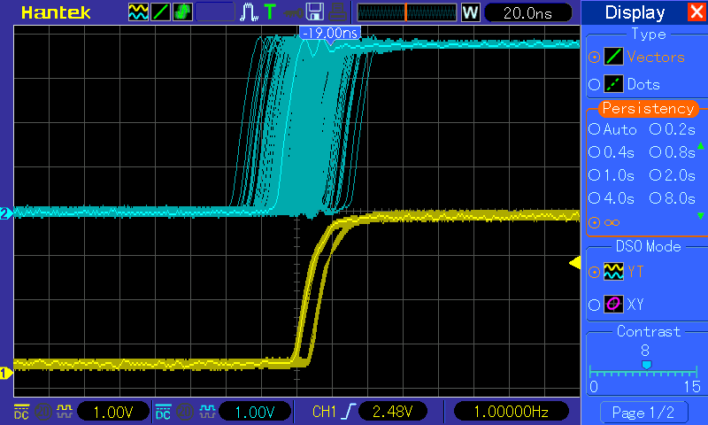
4.3.5.4. Test Results
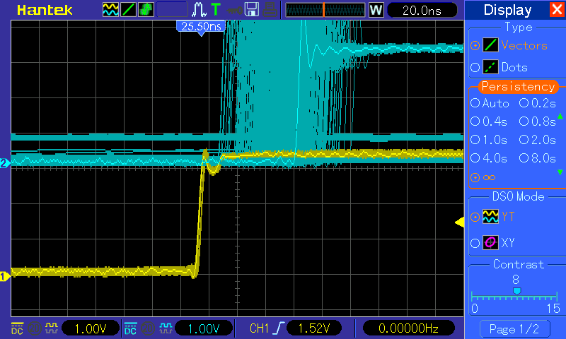
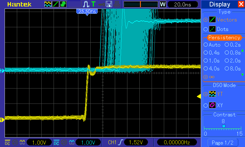
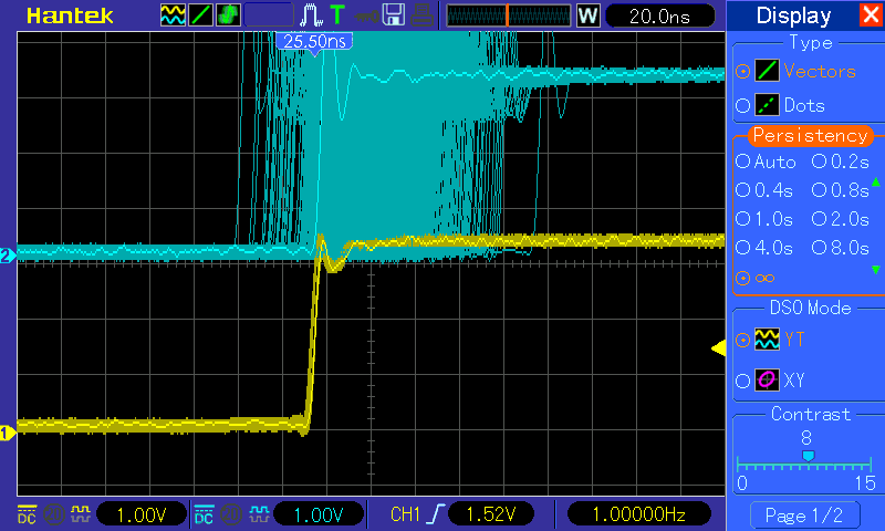
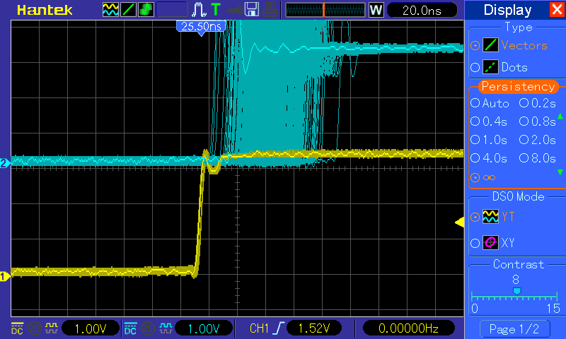
The following scope captures show the offset and jitters of the PPS signal between master and slave OC clock.
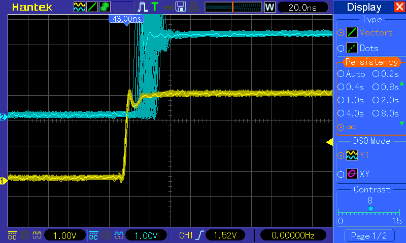
Figure 1: PPS: Oregano Master vs. PRU-ICSS Slave Port
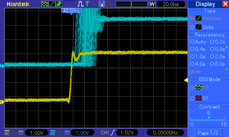
Figure 2: PPS: Oregano Master vs. GMAC Slave Port
4.3.6. PTP Boundary Clock
PTP boundary clock (BC) is supported on AM571x, AM572x and AM574x IDKs. In the case of AM571x IDK, BC with two to five ports is supported. These five ports can be any combination of GMAC and PRU ports, i.e., GMAC port, one or two ICSS1 PRU ports and one or two ICSS2 PRU ports. In the case of AM572x or AM574x IDK, BC with three ports, i.e., GMAC port and one or two ICSS2 PRU port, is supported.
4.3.6.1. Software Overview
There are four main components to the software together to provide the boundary clock functionality. These are, from low to high level, the ICSS PRU firmware, the related kernel ethernet drivers, the linuxptp ptp4l application and the linuxptp phc2sys application.
4.3.6.1.1. ICSS PRU Firmware
The ICSS PRU firmware used in BC is the PRP firmware (with PTP timestamping capability enabled) configured to run in Single Attached Node (SAN) mode or Dual Attached Node (DAN), the HSR firmware or the Dual EMAC firmware.
4.3.6.1.2. CPSW/CPTS Ethernet Driver
This is the same CPSW/CPTS Ethernet driver implemented for GMAC PTP OC.
4.3.6.1.3. ICSS-PRU/IEP Ethernet Driver
This is the same ICSS PRU Ethernet driver implemented for PTP OC.
4.3.6.1.4. BC Internal Clock Sync Monitoring Driver
A thin PTP BC driver layer is added on top of the ICSS-PRU/IEP and CPSW/CPTS Ethernet drivers in order to support the BC internal clock synchronization. This thin layer of driver is responsible for keeping track of which internal clock has its PPS enabled and giving permission to the requests by the internal clocks to generate PPS. Keeping track of PPS enablement is necessary because, at any instance of time, at most one clock can enable its PPS. For otherwise the SoC may be permanently damaged.
4.3.6.1.5. Application linuxptp ptp4l
This is the application provides the BC PTP functionality. In the AM57xx BC, the linuxptp ptp4l program is configured to run in jbod (just a bunch of device) mode, i.e., the BC PTP clock is modelled on more than one internal clocks instead of one single clock.
4.3.6.1.6. Application linuxptp phc2sys
The linuxptp phc2sys is used to perform synchronization of the internal clocks of a BC in jbod mode. For AM57xx BC, the phc2sys is enhanced to support the synchronization of the BC internal clocks by reading the timestamps of the PPS generated by the internal master clock and captured by the internal slave clocks. phc2sys then feeds the timestamps into linuxptp’s servo algorithm. The algorithm then produces the needed clock adjustment, usually in ppb of the nominal clock frequency, which is then passed to the kernel driver for clock adjustment by calling Linux PTP subsystem’s standard API.
4.3.6.1.7. Internal Clock Synchronization
Although the PTP clock time in the PTP network of the BC appears coming from one clock source, the PTP clock time available on the AM57xx ethernet ports are actually generated by different clocks internally. In particular, the PTP clock time on the CPSW GMAC port is generated by the CPTS module, and the PTP clock time on the ICSS PRU ports is generated by the corresponding IEP module on the respective ICSS. Since these clocks are running on their own separately, thus some internal synchronization mechanism is needed in order to make the AM57xx BC internal clocks appear as one clock source in the PTP network.
The internal clock synchronization can be considered in two parts. The first part is the alignment of the clock time up to within one second. This can easily be done by just reading one internal clock’s time and write it to the other internal clock by application software alone under the assumption that the whole read and write operation takes less than one second. The other part of synchronization is to align the two clocks’ time to the second boundary.
In this AM57xx BC implementation, the alignment of two internal clocks’ time to the second boundary is done by using the PPS generated by one internal (master) clock latched into another internal (slave) clock. This means that the PPS received by an internal clock is timestamped. This timestamp is then consumed by a servo application in the calculation of the adjustment needed in order to align the internal slave clock’s second boundary to that of the internal master clock.
Here the internal master clock of the BC is the internal clock that is synchronized to a PTP master clock over the PTP network, i.e., the corresponding ethernet port is in PTP slave port state.
4.3.6.2. Hardware Overview
For AM57xx IDK BC, since PPS generated by one internal clock needs to be latched into another internal clock, hardware, mainly blue wire, modifications are needed in order to achieve the latching of the PPS generated by one internal clock into another internal clock.
Refer to the Hardware Modifications
4.3.6.3. Test Setup/Procedure
4.3.6.3.1. Sample BC Setups
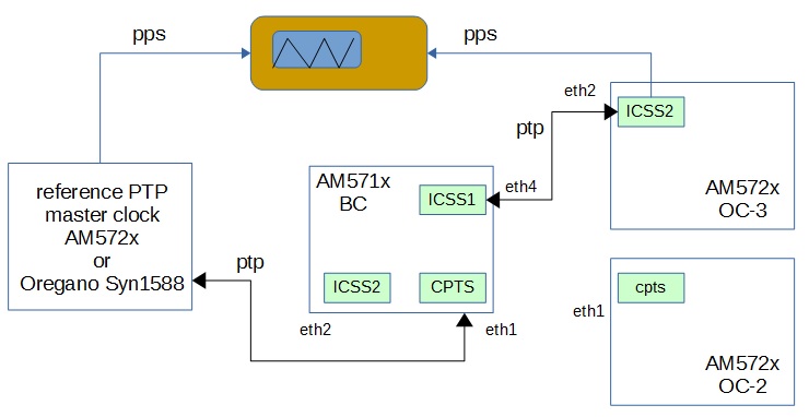
A sample set up for 3-port BC for testing purpose is shown below.
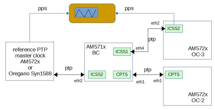
In this scenario, the BC ICSS2 PRU port (interface eth2) is in PTP slave state (ICSS2-IEP is the BC internal master clock). The other two ports, BC ICSS1 (interface eth4) and BC CPSW/CPTS (interface eth1) are in PTP master state (ICSS1-IEP and CPTS are the BC internal slave clocks).
A sample set up for BC with HSR/PRP ports for testing purpose is shown below.
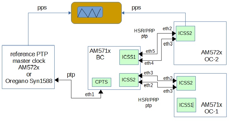
In this scenario, the BC CPSW/CPTS (interface eth1) is in PTP slave state (CPTS is the BC internal master clock). The other two ports, BC ICSS1 (interface eth4/eth5) and BC ICSS2 (interface eth2/3) are in PTP master state (ICSS1-IEP and ICSS2-IEP are the BC internal slave clocks).
Getting a PTP master clock ready
Start a reference PTP master clock that is connected in the PTP network as shown in the sample setup.
If the PTP master clock is an AM572x OC running linuxptp ptp4l, and for testing purpose, a line such as
clockClass 6
in the [global] section of the OC’s linuxptp configuration file can be helpful to make sure that the OC will be a master clock. Refer to PTP Ordinary Clock for starting an AM57xx OC.
Preparation on the AM57xx BC IDK
This section assumes that an AM571x is used. It should be similar for AM572x (or AM574x IDK) except that information about ICSS1 PRU (PRUSS1), eth4 and eth5 are not applicable.
4.3.6.3.2. Hardware
AM571x IDK
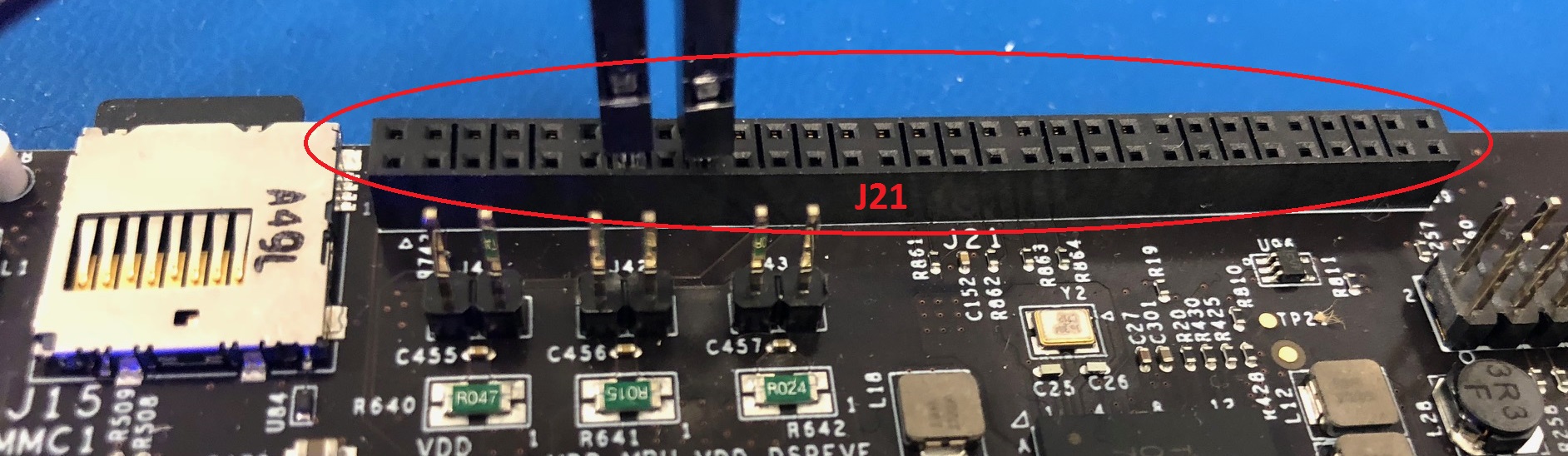
Connect the following 4 pins together. See the AM571x Mod List for more details.
| Wire on AM571x IDK | Signal |
|---|---|
| lower yellow wire | timer15 |
| J21-18 right blue wire | pr2_edc_latch0_out |
| J21-20 purple wire | pr1_edc_latch0_out |
| J21-54 left blue wire | pr1_edc_sync0_out |
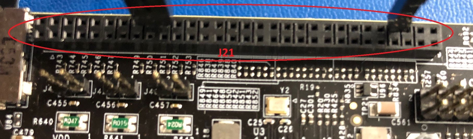
Example: See below pictures (J21 is the connector along the top right edge)
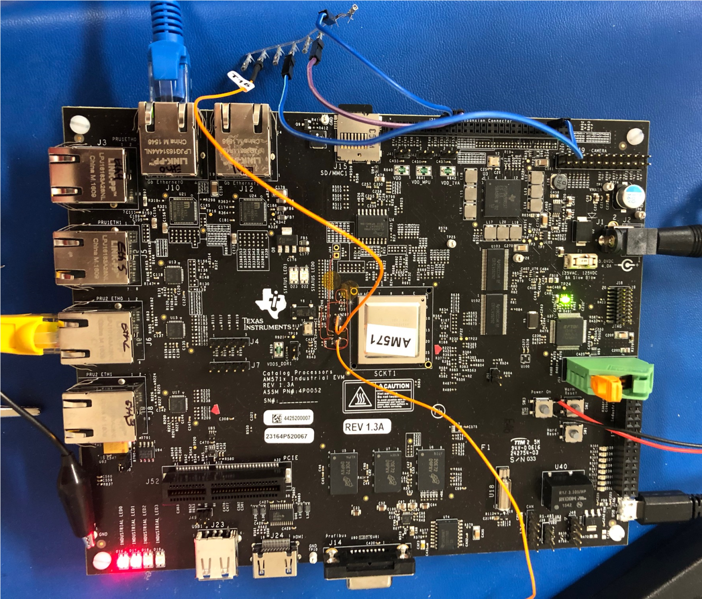
and this more J21 focused of the same picture above
AM572x and AM574x IDK
Connect the following 3 pins together. See the AM572x Mod List for more details.
| Wire on AM574x IDK | Signal |
|---|---|
| Center left black wire | timer15 |
| J21-13 black wire | pr2_edc_latch0_out |
| J21-17 white wire | pr1_edc_sync0_out |
Example: See below pictures (J21 is the connector along the top right edge)
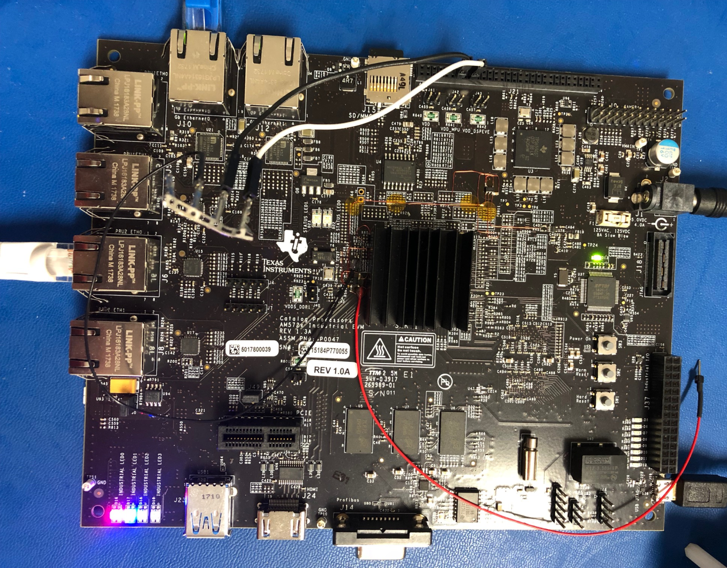
and this more J21 focused of the same picture above
4.3.6.3.3. Software
See a complete sample log for AM571x BC log here. As is shown in the log, right after the root login, the content of some shell scripts are displayed. Some of the scrits are for retrieving system information while others are for performing configurations. These sample scripts are for informational purpose only.
If using the PRP firmware, make sure to boot up the kernel with the parameters
- ti_prueth.pruss1_ethtype=2
- ti_prueth.pruss2_ethtype=2
in the bootargs. The firmware
- am57xx-pru0-pruprp-fw.elf
- am57xx-pru1-pruprp-fw.elf
will be loaded.
Make sure the following two lines appear in the start up log:
prueth pruss2_eth: TI PRU ethernet (type 2) driver initialized
prueth pruss1_eth: TI PRU ethernet (type 2) driver initialized
Once the AM57xx IDK is boot into kernel prompt, use command, for example,
$ ls /sys/devices/platform/pruss1_eth/net
  eth4/  eth5/
to see which interface is available on which ICSS. For GMAC port, use the command
$ ls /sys/devices/platform/44000000.ocp/48484000.ethernet/net
  eth0/ eth1/
If using PRP firmware configured to run in SAN mode, enable EMAC mode on each of the ICSS PRU interfaces (assuming eth2 and eth3 are on ICSS2, eth4 and eth5 are on ICSS1):
$ echo 1 > /sys/devices/platform/pruss2_eth/net/eth2/prp_emac_mode
$ echo 1 > /sys/devices/platform/pruss2_eth/net/eth3/prp_emac_mode
$ echo 1 > /sys/devices/platform/pruss1_eth/net/eth4/prp_emac_mode
$ echo 1 > /sys/devices/platform/pruss1_eth/net/eth5/prp_emac_mode
Next, configure each BC interface with a proper IP address. For example,
$ ifconfig eth1 192.168.1.1
$ ifconfig eth2 192.168.2.1
$ ifconfig eth4 192.168.4.1
If using PRP firmware configured to run in DAN mode, configure each BC interface with a proper IP address. For example,
$ ifconfig eth1 192.168.1.1
$ ifconfig eth2 hw ether 70:FF:76:1C:0E:8C
$ ifconfig eth3 hw ether 70:FF:76:1C:0E:8C
$ ethtool -K eth2 prp-rx-offload on
$ ethtool -K eth3 prp-rx-offload on
$ ifconfig eth2 up
$ ifconfig eth3 up
$ ip link add name prp0 type prp slave1 eth2 slave2 eth3 supervision 45 version 1
$ ifconfig prp0 192.168.2.1
$ ifconfig eth4 hw ether 70:FF:76:1C:0E:90
$ ifconfig eth5 hw ether 70:FF:76:1C:0E:90
$ ethtool -K eth4 prp-rx-offload on
$ ethtool -K eth5 prp-rx-offload on
$ ifconfig eth4 up
$ ifconfig eth5 up
$ ip link add name prp1 type prp slave1 eth4 slave2 eth5 supervision 45 version 1
$ ifconfig prp1 192.168.4.1
If using the HSR firmware, make sure to boot up the kernel with the parameters
- ti_prueth.pruss1_ethtype=1
- ti_prueth.pruss2_ethtype=1
in the bootargs. The firmware
- am57xx-pru0-pruhsr-fw.elf
- am57xx-pru1-pruhsr-fw.elf
will be loaded.
Make sure the following two lines appear in the start up log:
prueth pruss2_eth: TI PRU ethernet (type 1) driver initialized
prueth pruss1_eth: TI PRU ethernet (type 1) driver initialized
Once the AM57xx IDK is boot into kernel prompt, use command, for example,
$ ls /sys/devices/platform/pruss1_eth/net
  eth4/  eth5/
to see which interface is available on which ICSS. For GMAC port, use the command
$ ls /sys/devices/platform/44000000.ocp/48484000.ethernet/net
  eth0/ eth1/
Next, configure each BC interface with a proper IP address. For example,
$ ifconfig eth1 192.168.1.1
$ ifconfig eth2 hw ether 70:FF:76:1C:0E:8C
$ ifconfig eth3 hw ether 70:FF:76:1C:0E:8C
$ ethtool -K eth2 hsr-rx-offload on
$ ethtool -K eth3 hsr-rx-offload on
$ ifconfig eth2 up
$ ifconfig eth3 up
$ ip link add name hsr0 type hsr slave1 eth2 slave2 eth3 supervision 45 version 1
$ ifconfig hsr0 192.168.2.1
$ ifconfig eth4 hw ether 70:FF:76:1C:0E:90
$ ifconfig eth5 hw ether 70:FF:76:1C:0E:90
$ ethtool -K eth4 hsr-rx-offload on
$ ethtool -K eth5 hsr-rx-offload on
$ ifconfig eth4 up
$ ifconfig eth5 up
$ ip link add name hsr1 type hsr slave1 eth4 slave2 eth5 supervision 45 version 1
$ ifconfig hsr1 192.168.4.1
Starting the BC applications
Refer to the sample linuxptp BC configuration files bc.cfg, bc_hsr.cfg and bc_prp.cfg as described below:
bc.cfg: BC with GMAC and four ICSS ports
[global]
sanity_freq_limit            0
step_threshold               0.000002
tx_timestamp_timeout         10
logMinPdelayReqInterval      0
logSyncInterval              0
logAnnounceInterval          0
announceReceiptTimeout       3
syncReceiptTimeout           2
twoStepFlag                  1
summary_interval             0
doubly_attached_clock        2

[eth1]
boundary_clock_jbod          1
egressLatency                146
ingressLatency               346
delay_mechanism              P2P
network_transport            L2

[eth2]
boundary_clock_jbod          1
delay_mechanism              P2P
network_transport            L2
egressLatency                726
ingressLatency               186
fault_reset_interval         0

[eth3]
boundary_clock_jbod          1
delay_mechanism              P2P
network_transport            L2
egressLatency                726
ingressLatency               186
fault_reset_interval         0


[eth4]
boundary_clock_jbod          1
delay_mechanism              P2P
network_transport            L2
egressLatency                726
ingressLatency               186
fault_reset_interval         0

[eth5]
boundary_clock_jbod          1
delay_mechanism              P2P
network_transport            L2
egressLatency                726
ingressLatency               186
fault_reset_interval         0
bc_prp.cfg: BC with GMAC and two PRP ports:
[global]
sanity_freq_limit            0
step_threshold               0.000002
tx_timestamp_timeout         10
logMinPdelayReqInterval      0
logSyncInterval              0
logAnnounceInterval          0
announceReceiptTimeout       3
syncReceiptTimeout           2
twoStepFlag                  1
summary_interval             0
doubly_attached_clock        2

[eth1]
boundary_clock_jbod          1
egressLatency                146
ingressLatency               346
delay_mechanism              P2P
network_transport            L2

[prp0]
boundary_clock_jbod          1
redundancy                   2
delay_mechanism              P2P
network_transport            L2

[eth2]
boundary_clock_jbod          1
redundancy                   2
redundancy_master_interface  prp0
redundancy_slave_number      1

delay_mechanism              P2P
network_transport            L2
egressLatency                726
ingressLatency               186
fault_reset_interval         0

[eth3]
boundary_clock_jbod          1
redundancy                   2
redundancy_master_interface  prp0
redundancy_slave_number      2

delay_mechanism              P2P
network_transport            L2
egressLatency                726
ingressLatency               186
fault_reset_interval         0


[prp1]
boundary_clock_jbod          1
redundancy                   2
delay_mechanism              P2P
network_transport            L2

[eth4]
boundary_clock_jbod          1
redundancy                   2
redundancy_master_interface  prp1
redundancy_slave_number      1

delay_mechanism              P2P
network_transport            L2
egressLatency                726
ingressLatency               186
fault_reset_interval         0

[eth5]
boundary_clock_jbod          1
redundancy                   2
redundancy_master_interface  prp1
redundancy_slave_number      2

delay_mechanism              P2P
network_transport            L2
egressLatency                726
ingressLatency               186
fault_reset_interval         0
bc_hsr.cfg: BC with GMAC and two HSR ports:
[global]
sanity_freq_limit            0
step_threshold               0.000002
tx_timestamp_timeout         10
logMinPdelayReqInterval      0
logSyncInterval              0
logAnnounceInterval          0
announceReceiptTimeout       3
syncReceiptTimeout           2
twoStepFlag                  1
summary_interval             0
doubly_attached_clock        2

[eth1]
boundary_clock_jbod          1
egressLatency                146
ingressLatency               346
delay_mechanism              P2P
network_transport            L2

[hsr0]
boundary_clock_jbod          1
redundancy                   1
delay_mechanism              P2P
network_transport            L2

[eth2]
boundary_clock_jbod          1
redundancy                   1
redundancy_master_interface  hsr0
redundancy_slave_number      1

delay_mechanism              P2P
network_transport            L2
egressLatency                726
ingressLatency               186
fault_reset_interval         0

[eth3]
boundary_clock_jbod          1
redundancy                   1
redundancy_master_interface  hsr0
redundancy_slave_number      2

delay_mechanism              P2P
network_transport            L2
egressLatency                726
ingressLatency               186
fault_reset_interval         0


[hsr1]
boundary_clock_jbod          1
redundancy                   1
delay_mechanism              P2P
network_transport            L2

[eth4]
boundary_clock_jbod          1
redundancy                   1
redundancy_master_interface  hsr1
redundancy_slave_number      1

delay_mechanism              P2P
network_transport            L2
egressLatency                726
ingressLatency               186
fault_reset_interval         0

[eth5]
boundary_clock_jbod          1
redundancy                   1
redundancy_master_interface  hsr1
redundancy_slave_number      2

delay_mechanism              P2P
network_transport            L2
egressLatency                726
ingressLatency               186
fault_reset_interval         0
Start ptp4l in the background and with display log to stdout enabled:
$ ptp4l -f bc.cfg -m &
Wait to see the PTP slave port clock is sync and stabilized, for example, seeing similar lines:
ptp4l[304.713]: rms    7 max   12 ( -12,    1) freq  -8253 +/-   4 delay     7 +/-   1
ptp4l[305.714]: rms    2 max    4 (  -4,    2) freq  -8248 +/-   3 delay     8 +/-   0
ptp4l[306.714]: rms    2 max    3 (  -3,    3) freq  -8248 +/-   3 delay     8 +/-   0
then start phc2sys to perform the BC internal clock sync in the background
$ phc2sys -a -X -g eth1 -S 0.000002 -L 0 -m &
where the new options added in this implementation are
-X: use extts (pps) to perform BC internal clock synchronization.
-g: specify which interface is the GMAC port interface
-S: specify step threshold
-L: specify sanity frequency limit in ppb
Lines similar to the following should be displayed after a few seconds (mixed with the “ptp4l[304.713]: rms ...” lines from ptp4l) :
phc2sys[373.480]: eth4 phc offset       -14 s2 freq   -8311
phc2sys[373.500]: eth1 phc offset       -18 s2 freq   -8315
Start an AM57xx OC in slave only mode connected to a BC’s master port, for example, the AM572x OC-3 in the sample setup. To make sure the OC is started in slave only mode, the ptp4l command
$ ptp4l -2 -P -f oc.cfg -s -m
can be used. The slave OC’s PPS can then be measured against the reference PTP master clock’s PPS.
Forcing BC Port State Change (for Testing Purpose)
To force a port state change on the BC ports for testing purpose, one can bring down the current reference PTP master clock and bring up another reference PTP master clock connected to, for example, the BC’s eth1 interface in the sample setup. Or simply rearrange the cable connections in the sample setup as shown below.
See here for a sample log when the BC’s cables are reconnected. The sample log starts right before when the cable is disconnected from eth2 on BC’s ICSS2 in the sample setup.
4.3.6.4. Test Results
BC (GMAC ICSS2)
BC (GMAC ICSS1)
BC (ICSS2 GMAC)
BC (ICSS1 GMAC)
BC (ICSS2 ICSS1)
BC (ICSS1 ICSS2)
BC (GMAC ICSS1-HSR)

BC (GMAC ICSS1-PRP)
4.3.6.5. Limitations
- In the current implementation, when running more than one OC, for example, ICSS1 OC and ICSS2 OC, only one pps can be enabled through command line. In this example, if ptp1 is the device for ICSS2 OC and ptp2 is the device for ICSS1 OC, then only one of the following will be allowed:
echo 1 > /sys/devices/platform/pruss2_eth/ptp/ptp1/pps_enable
or
echo 1 > /sys/devices/platform/pruss1_eth/ptp/ptp2/pps_enable
The same is true for other combinations. The intention is to avoid having more than one PPS enabled when the IDK has the HW mod mentioned in Hardware Modifications for AM57xx IDK BC and the pins are tied together.
4.3.7. HSR OC TC
4.3.7.1. Overview
The purpose of this section and the sub-sections there in is to provide an overview of Linux PTP ordinary clock (OC) and transparent clock (TC) in a HSR network, the internal mechanism of how HSR OC and TC works on TI’s AM57xx processors, required software and hardware, test setup and procedure, and our test results. In this section boundary clock (BC) with connections in HSR network is not considered.
4.3.7.2. PTP OC, TC in HSR Network
The implementation of the HSR OC and TC on AM57xx is based on the IEEE-62439-03-2016 recommendation. Currently it supports only two-step HSR hybrid clock (OC+TC) without BMCA enhanced for HSR. Future releases will fill in the missing features.
Since HSR network is a ring topology network, the PTP clocks in such networks must handle PTP messages communicated over the two slave ports under a HSR interface. In addition to originating its own PTP messages and receiving PTP messages, a HSR clock must also forward PTP messages, except link local messages, for downstream nodes to process. In other words, a PTP clock in a HSR network must either be a standalone TC or an OC which also functions as a TC, i.e. a hybrid clock, as is defined in IEEE-62439-03-2016.
4.3.7.2.1. Hardware
On AM57xx platforms, the HSR PTP OC and TC functionalities are provided by the ICSS-PRU hardware modules.
4.3.7.2.2. Software
On the software side, the key software modules for supporting the HSR PTP clock functionalities include the HSR firmware, PRU ethernet driver, core HSR layer, core network layer and the application linuxptp. The Linux kernel modules are responsible passing timestamps and HSR tag information to application linuxptp on receive path. On transmit path, those kernel modules are also responsible for accepting HSR tag information (if passed in by application, for example, for delay corrected FOLLOW-UPs that are passing through the node) and sending frames out over a specific HSR slave port indicated by the application. Sending a PTP message over a specified HSR slave port is needed, for example, for FOLLOW-UP messages.
For OC functionality, other than handling the HSR tag information, the processing of PTP messages by the application is similar to the regular OC functionality without HSR, although the application running on a slave OC must only allow the ACTIVE port to adjust its PTP clock.
One of the key features of a TC is the capability of being able to make timestamp “corrections” in the FOLLOW-UP message for a SYNC message. This is achieved as follows. When the HSR firmware receives a SYNC message, it passes both the rx timestamp and cut-through forward tx timestamp of the SYNC message to the host driver. These timestamps are then passed to the application, along with the SYNC, by the kernel drivers. With the rx timestamp and the cut-through tx timestamp of the SYNC message, the application linuxptp can then add the residence time delay, in addtion to the peer path delay, in the correctionField of the SYNC’s FOLLOW-UP message before the FOLLOW-UP is forwarded to next hop.
4.3.7.3. Required hardware and software to setup HSR OC, TC
4.3.7.3.1. Hardware Modifications for AM57xx IDK HSR OC, TC
The hardware modifications needed for AM57xx IDK to function as HSR OC and TC are the same as those required for regular OC and BC. These modifications are for PPS generation on the AM57xx IDK.
4.3.7.3.1.1. AM571x
See the AM571x Mod List for more details of the hardware modification specification. Sample assembly photos can be found here
4.3.7.3.1.2. AM572x and AM574x
See the AM572x/AM574x Mod List for more details of the hardware modification specification.
4.3.7.3.2. Software
AM57xx HSR OC and TC are supported with limitations in ProcessorSDK Linux release starting from version 4.3.0.6. See the section Limitations below for more details.
Remark Because PPS needs to be enabled in PTP tests, so the devicetree (dtb) needs to be loaded when booting the kernel must contain the PPS configurations. But by default, after make Linux_install, the default devicetree is not the right one for enabling PPS:
$ ls -l /rel4306/rootfs/boot/am571x-idk.dtb
lrwxrwxrwx 1 user user32 Apr 20 22:54 /rel4306/rootfs/boot/am571x-idk.dtb -> devicetree-uImage-am571x-idk.dtb
The correct dtb needed for enabling pps is
$ ls -l /rel4306/rootfs/boot/am571x-idk-pps.dtb
lrwxrwxrwx 1 user user 36 Apr 20 22:54 /rel4306/rootfs/boot/am571x-idk-pps.dtb -> devicetree-uImage-am571x-idk-pps.dtb
For PTP tests, the default dtb am571x-idk.dtb needs to be replaced by am571x-idk-pps.dtb when creating the SDCard for kernel bootup.
One way to do that is, for example, in the boot directory overwrite the default dtb by the pps dtb
$ cd /rel4306/rootfs/boot/
$ rm am571x-idk.dtb
$ cp am571x-idk-pps.dtb  am571x-idk.dtb
And then follow the usual steps to create the SDCard.
Similarly for AM572x.
4.3.7.4. Test Setup/Procedure
4.3.7.4.1. Test 1. With a hybrid clock (OC+TC) between master and slave clock
4.3.7.4.1.1. A Sample 3 HSR Hybrid Clock Setup
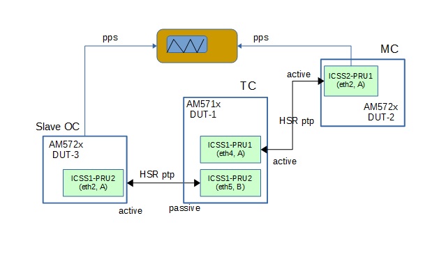
Although each clock in this setup is a HSR hybrid clock, the role that each clock plays in this test is as follows:
DUT-2 : AM572x : Master clock
DUT-1 : AM571x : Transparent clock
DUT-3 : AM572x : Slave clock
Note
In this release BMCA enhanced for HSR is not supported, hence the connection is not a HSR close-loop network.
4.3.7.4.1.2. Procedure
The script file setup_hsr.sh and clock configuration files e.g. dut_1_hsr_oc.cfg, dut_2_hsr_oc.cfg, dut_3_hsr_oc.cfg (each identical, same as listed in PTP Redundancy section for HSR) will be used in the setup of the tests.
- For each DUT-X, copy the setup script setup_hsr.sh and the clock configuration file dut_X_hsr_oc.cfg into the target filesystem of DUT-X. For the sample setup above
DUT-2 : setup_hsr.sh : dut_2_hsr_oc.cfg
DUT-1 : setup_hsr.sh : dut_1_hsr_oc.cfg
DUT-3 : setup_hsr.sh : dut_3_hsr_oc.cfg
- Connect the 3 AM57xx IDKs as shown above.
- Boot IDK into u-boot prompt and to specify HSR firmware is to be loaded, do
$ setenv pruss1_ethtype 1
$ setenv pruss2_ethtype 1
$ saveenv
- Boot IDK into kernel prompt.
- Modify the top fields in setup_hsr.sh to reflect the HSR slave ports’ MAC addresses and IP address of the DUT’s HSR interface. The ETHA or ETHB fields may also need to be modified if an ICSS different from the one shown in the picture is used.
- Run the modified setup_hsr.sh script to configure the hsr0 interface.
- After each IDK is bootup, do a ping to make sure the setup is fine.
- On DUT-2 (master OC) do
$ ptp4l -2 -P -f dut_2_hsr_oc.cfg -m
- On DUT-1 (OC+TC) do
$ ptp4l -2 -P -f dut_1_hsr_oc.cfg -m -s
- On DUT-3 (slave OC) do:
$ ptp4l -2 -P -f dut_3_hsr_oc.cfg -m -s
- Open a telnet terminal to DUT-2 and enable PPS:
$ echo 1 > /sys/devices/platform/pruss2_eth/ptp/ptp1/pps_enable
- Open a telnet terminal to DUT-3 and enable PPS:
$ echo 1 > /sys/devices/platform/pruss2_eth/ptp/ptp1/pps_enable
- Measure PPS jitter between DUT-2 (master) and DUT-3 (slave)
- See sample capture files dut_1_log.txt, dut_2_log.txt, dut_3_log,txt for more detail.
Remark: When enabling the ICSS2 PPS, the ptpX entry associated with ICSS2 on DUT-2 and DUT-3 may be different on different setups. Run the script ptpinfo.sh to find out the correct ptpX entry that is associated with ICSS2 on each platform.
From the sample display of the ptpinfo.sh script below, the ptpX entry associated with ICSS2 (PRUSS2 timer) is ptp1.
root@am57xx-evm:~# ./ptpinfo.sh
ls /sys/devices/platform/44000000.ocp/48484000.ethernet/net/
eth0  eth1
ls /sys/devices/platform/pruss2_eth/net
eth2  eth3
lrwxrwxrwx    1 root     root             0 Apr 20 19:11 ptp0 -> ../../devices/platform/44000000.ocp/48484000.ethernet/ptp/ptp0
lrwxrwxrwx    1 root     root             0 Apr 21 21:18 ptp1 -> ../../devices/platform/pruss2_eth/ptp/ptp1
ptp clock names:
/sys/class/ptp/ptp0 : CTPS timer
/sys/class/ptp/ptp1 : PRUSS2 timer
pps's ptp device:
/sys/class/pps/pps0 : ptp0
/sys/class/pps/pps1 : ptp1
root@am57xx-evm:~#
4.3.7.5. Test Results
4.3.7.5.1. Test 1. With a hybrid clock (OC+TC) between master and slave clock
4.3.7.5.2. Test 2. Without a hybrid clock between Master and Slave Clock
4.3.7.6. Limitations
The current implementation of HSR PTP OC and TC has the following limitations
- Only HSR hybrid clock is supported. Standalone TC is not supported.
- Only 2-step clock is supported.
- BMCA enhanced for HSR is not supported.
- The two slave ports of an HSR interface is assumed to have the same characteristics such as the linuxptp egressLatency and ingressLatency configurations are the same.
4.3.7.7. Known Issues
4.3.8. PTP Roadmap
The following features are not yet supported, but will be added in the future: