3.6. PRU-ICSS / PRU_ICSSG
3.6.1. Getting Started with PRU-ICSS
Overview
Note
This section covers the software aspects of getting started on the PRU-ICSS and the PRU_ICSSG. Hardware information, training material, software development resources, and more are currently located on the PRU-ICSS wiki page
The PRU Software Support Package provides support for the PRU-ICSS Subsystem in AM335x, AM437x, AM57xx, and K2G devices. This package contains:
- Support for ARM<->PRU interaction via remoteproc and rpmsg Linux
drivers
- Remoteproc supports basic control functions such as firmware load, start/halt, simple debug, and interrupt managing
- Rpmsg supports message passing
- Basic firmware examples showing simple functionality
- Register header files for easy register programming
- Library/API for controlling vrings (used for rpmsg)
Things to Obtain
- Code Composer Studio
- PRU Code Generation Tools (you can also get these tools through the CCS App Center)
- ARM running Linux
- Linux Processor SDK for AM335x, Linux Processor SDK for AM437x, Linux Processor SDK for AM57xx, Linux Processor SDK for AM65xx or Linux Processor SDK for K2G
- The PRU Software Support Package is built into the Linux Processor SDK in the ‘<%SDK_INSTALL_DIR%>/example-applications/’ folder
- ARM running RTOS
- RTOS Processor SDK for AM335x, RTOS Processor SDK for AM437x, RTOS Processor SDK for AM57xx, RTOS Processor SDK for AM65xx or RTOS Processor SDK for K2G
- PRU Software Support Package - Contains header files and register mappings
Installation of Tools
Tools installation paths are generally fairly arbitrary, but we do have a few requirements once you have installed to your preferred directory.
Linux
- Install Processor SDK to the directory of your choosing Follow the installation instructions found here. Location does not matter, but the default installation directory is strongly suggested and makes using the SDK’s scripts much easier.
- Install the PRU Software Support Package into the SDK you chose above Starting with Linux Processor SDK v2.0.1.7 the support package is built into the SDK at the ‘examples-applications/pru-icss-x.y.z/’ folder
- (Optional) Install CCS to the directory of your choosing CCS installation instruction for Linux can be found here. Makefiles are provided (in addition to CCS projects for most projects) in order to build all examples in the PRU Software Support Package. The ability to build the PRU projects using the Makefiles makes CCS completely optional in a Linux environment.
Windows
- There is no longer a standalone installer for the PRU Software Support Package You must now download the files from the public Git repository here.
- Install CCS to the directory of your choosing Installers can be found here.
How to Enable PRU Support in Kernel
How to Begin Programming
Programming the PRU core is not terribly different from programming any other core. Because we now have a C compiler we are able to write regular C code and have it perform tasks on the PRU cores. A great place to start development is to take a look at the Hands-on Labs that are provided in the PRU Software Support Package.
Register Header Files
Several register header files were created to help facilitate quick and easy configuration. In Linux, these are located in the <SDK_install_dir>/example-applications/pru-icss-x.y.z/include directory by default. In the Git repository these are located in the include folder. See the header files page for more information.
Special Considerations
There are a couple of special CPU registers available with different functionality.
- Writes to R30 control the General Purpose Output pins, and reads allow the user to determine the current state of those pins
- R31 is used to read General Purpose Input pins as well as the status
of the two PRU host interrupts (bits 30 and 31)
- Writes to R31 are used to generate interrupts - see the device-specific TRM for more information on how these work.
What Next?
For support please post questions on E2E Processor Support.
3.6.2. Header Files
Introduction
The header files for the PRU-ICSS were written in such a way so as to sit on top of the memory-mapped registers. They can be directly linked to that address range via the Linker Command File, but in the existing examples the header files are accessed via the Constant Table registers. The process of using cregister attributes to link header files to an address range through the Constant Table registers is described in the PRU Optimizing C/C++ Compiler User’s Guide. Information on cregisters are in the “Type Attributes” section. Information on the near and far keywords used in the current examples can be found in the section “The near and far Keywords”.
Layout
The register sets are grouped up into structures containing the appropriate gaps for reserved registers. Each register can be accessed as a full 32-bit register (although the ECAP peripheral does have some 16-bit registers) or at the bit-field level. This is so as to eliminate the need to do bit-masking at the register level.
Using the Headers
The process of using the headers is described in more detail in the “Type Attributes” section of the PRU Optimizing C/C++ Compiler User’s Guide.
In order to tie the structures to the appropriate Constant Table register we have to use a special trick with the PRU Code Generation Tools package. This process is described in more detail in the CGT Documentation here. For our purposes the linker command file found in each example project contains a “Memory” range for each of the Constant Table entries.
Once this is completed you will be able to access a peripheral register via the structure by accessing that structure’s members. The basic layout is like this:
union{ u32 register_name; struct { bit_field_names : bit_size; . . . } register_name_bit; }; . . . | } register_set;
Thus you can access a register programmatically through the structure (e.g., register_set.register_name[_bit.bitfield_name] = value).
3.6.3. Linux Drivers
3.6.3.1. RemoteProc and RPMsg
Introduction
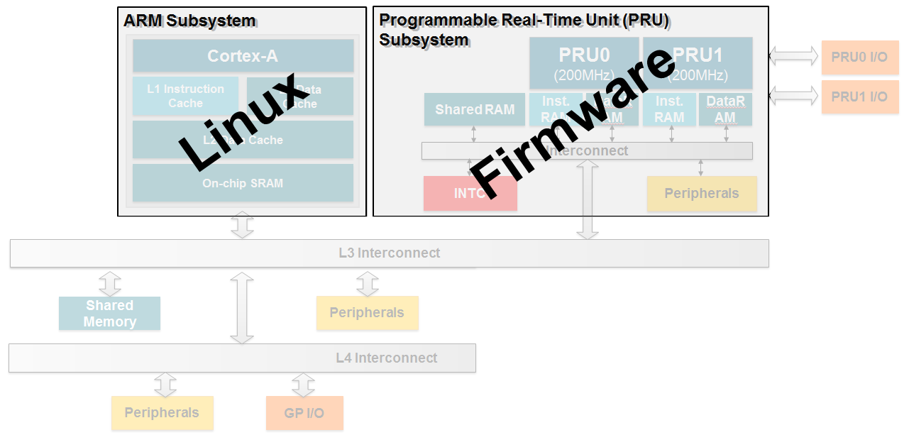
The host processor on TI’s Sitara family of devices is an ARM Cortex-A processor. Typically the ARM core is running Linux based on the Processor SDK. TI has developed custom pruss and pru_rproc (PRU Subsystem Remote Processor) drivers which will plug into this kernel. This provides an interface for the kernel to load firmware into the PRU core(s) and provides basic control such as start and halt. A message passing driver, named rpmsg_pru (remote processor message), has also been developed that allows the PRU and ARM cores to pass messages and buffers back and forth.
What do we need Linux to do?
The following is a list of services that Linux needs to provide in order to enable the PRU cores:
- Load firmware into the PRU cores
- Control PRU execution (start, stop, etc.)
- Manage resources (memory, interrupt mappings, etc.)
- Provide a method to send/receive messages
All of these services are provided through a combination of the pruss, pru_rproc, and rpmsg_pru Linux drivers that TI provides in the Processor SDK.
Remoteproc
Overview
Remoteproc is a framework that allows the ARM host processor(s) to load firmware into PRU cores, start the PRU cores, stop the PRU cores, and configure resources that the PRUs might need during their execution (such as configuring the PRUSS INTC module and providing shared buffers in DDR memory for message passing). The next section will discuss the process that happens when the remoteproc module loads the PRU cores with a firmware. Most of this happens transparently to the user when the pruss and pru_rproc modules are inserted but an understanding of the concepts below should help users to better understand how to debug problems with remoteproc should they arise.
Load Procedure
This section will walk through each step that the drivers takes as they load firmwares into the PRU cores and then run them.
Step 0
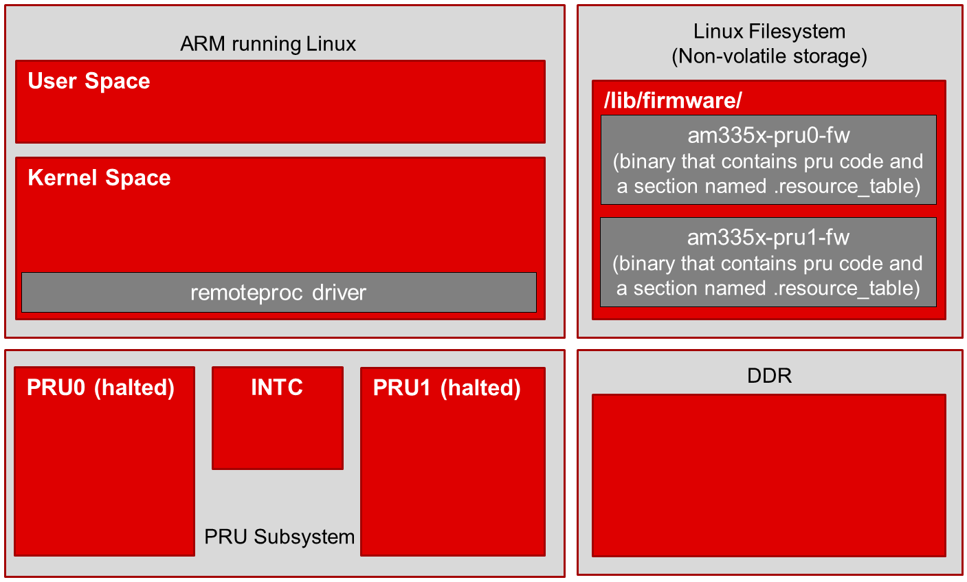
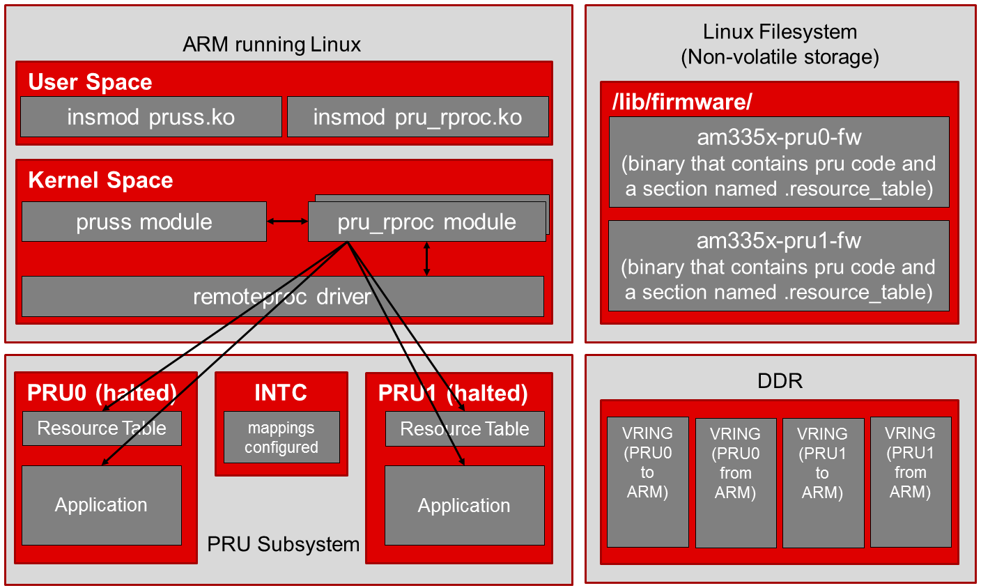
The four blocks in the image to right represent: The ARM core running Linux, the Linux filesystem where the PRU firmware binaries are initially stored, the PRU subsystem, and DDR memory. This image shows the initial state of the system before the pruss_remoteproc module is inserted.
- Remoteproc driver is included as a kernel driver. This is a core remoteproc driver that provides the load/run/halt/etc API to other more specific remoteproc drivers.
- A sysfs interface is also exposed to User Space to start/stop the PRU
cores as well as specify the firmware file to load.
- The sysfs interface is found at /sys/class/remoteproc/remoteprocN/ (e.g. remoteproc1 is PRU0 and remoteproc2 is PRU1 on the AM335x device (remoteproc0 is the M3 core used for power management functions)).
- PRU firmware binaries exist in the filesystem in the /lib/firmware/ directory.
Step 1
echo 'am335x-pru0-fw' > /sys/class/remoteproc/remoteproc1/firmwareecho 'am335x-pru1-fw' > /sys/class/remoteproc/remoteproc2/firmwareecho 'start' > /sys/class/remoteproc/remoteproc1/stateecho 'start' > /sys/class/remoteproc/remoteproc2/stateStep 2

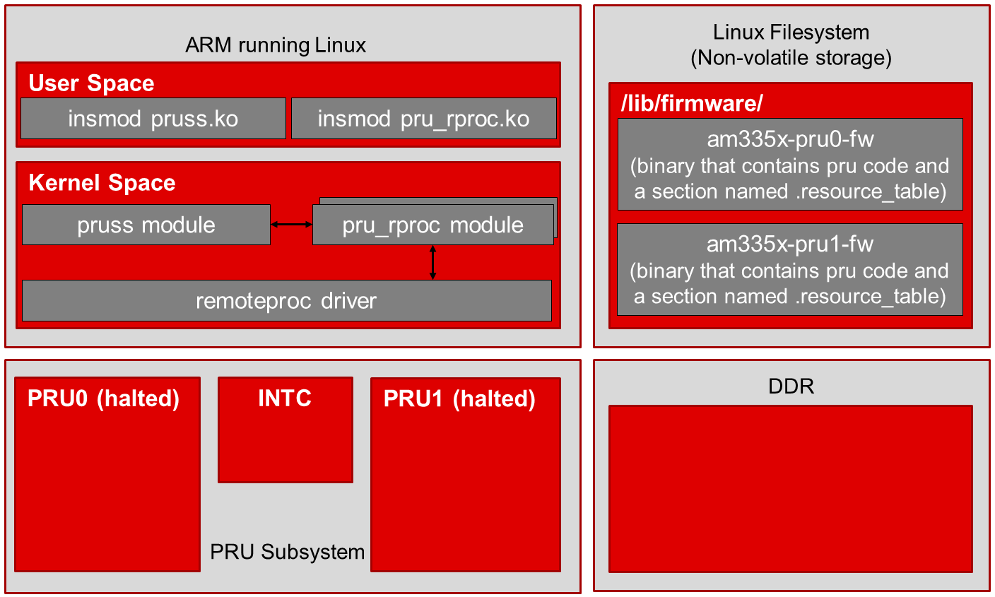
The pru_rproc module verifies two things before it proceeds with the firmware loading process.
- The pru_rproc modules checks for the existence of PRU firmware
binaries in the filesystem (as specified by the firmware entry in the
sysfs in step 1 above)
- These binaries must be located in the /lib/firmware/ directory
- am335x-pru0-fw and am335x-pru1-fw are the default names used for the AM335x device but any name can be used as long as the firmware exists in /lib/firmware/
- The pru_rproc module also parses the firmware binaries looking for a
section named .resource_table
- This .resource_table section of the firmware specifies the system resources that the PRUs will need during their program execution
Step 3
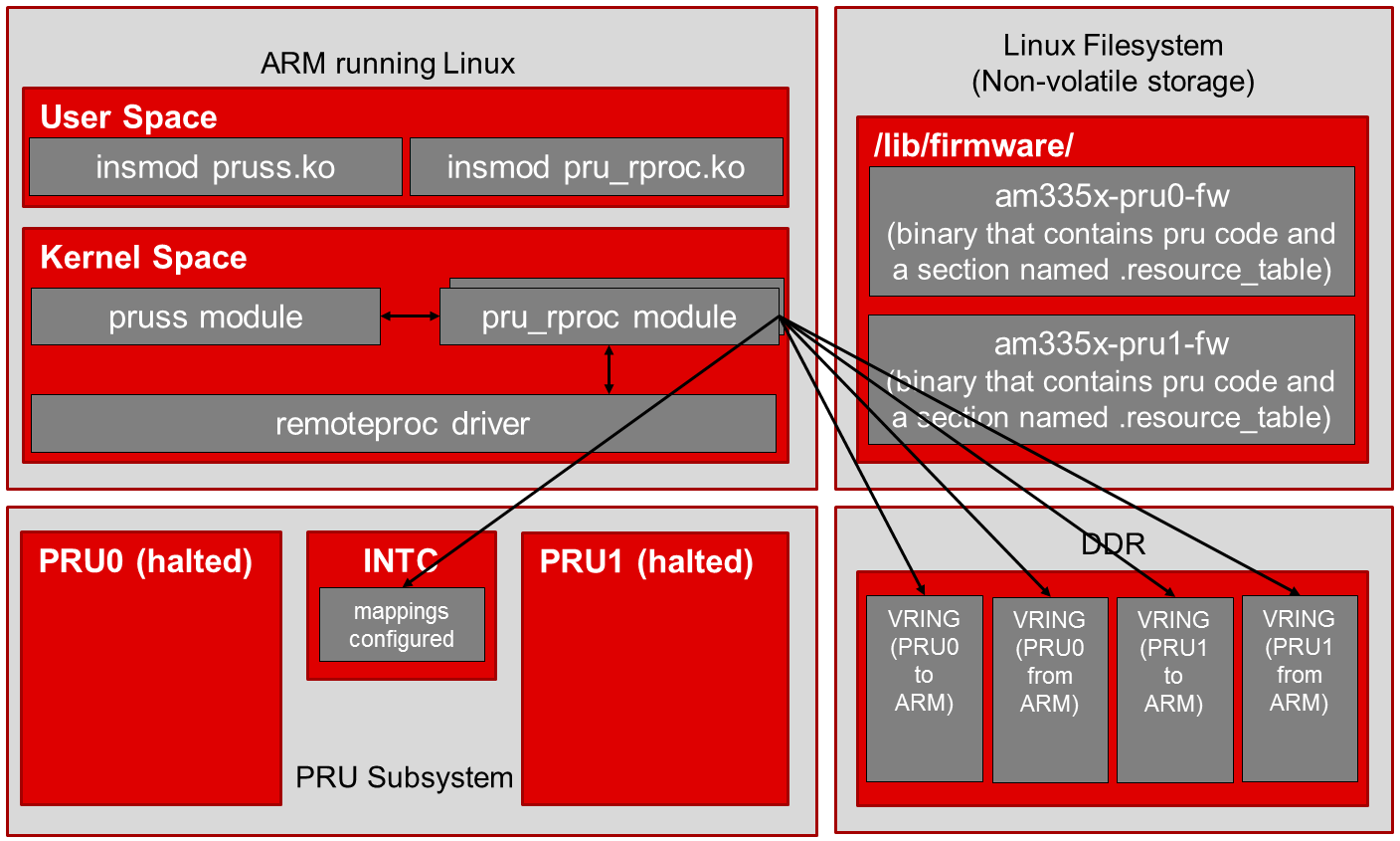
- The pru_rproc module configures all of the resources that are being requested by the firmwares
- In this case, that includes creating vrings in DDR memory for communication as well as setting up the interrupt mapping in the PRU subsystem INTC module
Step 4
Step 5

Now that everything is configured and the application code is in place, the pru_rproc module instructs the PRU cores to begin execution.
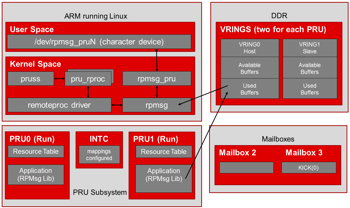
RPMsg
RPMsg is a message passing mechanism that requests resources through remoteproc and builds on top of the virtio framework. Shared buffers are requested through the resource_table and provided by the remoteproc module during PRU firmware loading (as shown in the remoteproc procedure above). The shared buffers are contained inside a vring data structure in DDR memory. There are two vrings provided per PRU core, one vring is used for messages passed to the ARM and the other vring is used for messages received from the ARM. System level mailboxes are used to notify cores (ARM or PRU) when new messages are waiting in the shared buffers.
There are two RPMsg software implementations provided in the Linux Processor SDK. On the ARM Linux side, RPMsg communication is received in kernel space. An interface module is provided (rpmsg_pru) that creates a character device in user space so that users can write/read to/from a character device in the file system to send/receive messages to/from the PRUs. On the PRU side, an RPMsg library is provided in the PRU Software Support Package that aims to abstract the communication to a point where a user’s code can just call the pru_rpmsg_receive and pru_rpmsg_send functions in order to communicate with the ARM core. Source code for the PRU RPMsg library is provided in the support package along with the ability to rebuild the library if changes are desired.
ARM to PRU
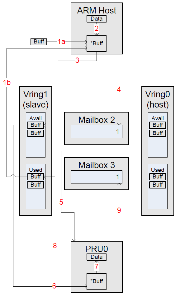
The diagram to the right shows the process that occurs when the ARM sends a message to the PRU. These steps are shown for illustrative purposes as the provided software in the SDK hides them in an abstraction layer.
- ARM Host Steps
- Step 1a: Allocate a new buffer -or-
- Step 1b: Get a Used buffer from the slave Vring
- Step 2: Copy data to be transferred into the buffer from Step 1
- Step 3: Add the newly filled buffer to the Available list in the slave Vring
- Step 4: Kick the slave Vring by writing its index (1) into a message in Mailbox 2
- PRU Steps
- Step 5: A Kick is discovered in Mailbox 2 with the index of the Kicked Vring (1). This indicates to the PRU that data is available for receive
- Step 6: Get the Available buffer from the slave Vring
- Step 7: Copy data to be received out of the buffer from Step 2
- Step 8: Add the now empty buffer to the Used list in the slave Vring
- Step 9: Kick the slave Vring by writing its index (1) into a message in Mailbox 3
PRU to ARM
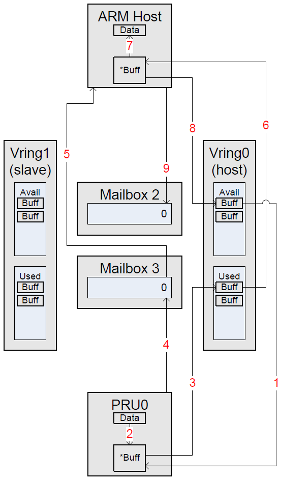
The diagram to the right shows the process that occurs when the PRU sends a message to the ARM. These steps are shown for illustrative purposes as the provided software in the SDK hides them in an abstraction layer.
- PRU Steps
- Step 1: Get an Available buffer from the host Vring
- Step 2: Copy data to be transferred into the buffer from Step 1
- Step 3: Add the newly filled buffer to the Used list in the host Vring
- Step 4: Kick the host Vring by writing its index (0) into a message in Mailbox 3
- ARM Host Steps
- Step 5: An interrupt signals that Mailbox 3 was kicked with the index of Vring (0). This indicates to the ARM Host that data is available for receive
- Step 6: Get the Used buffer from the host Vring
- Step 7: Copy data to be received out of the buffer from Step 2
- Step 8: Add the now empty buffer to the Available list in the host Vring
- Step 9: Kick the host Vring by writing its index (0) into a message in Mailbox 2
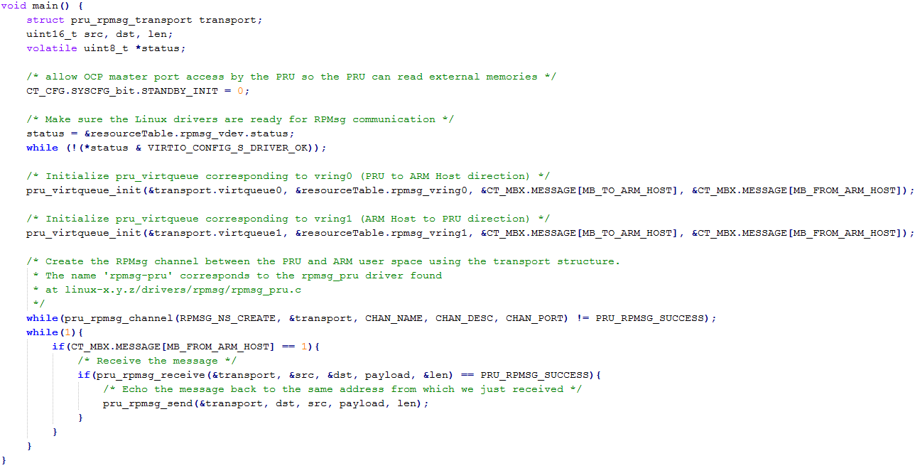
RPMsg PRU Code Example
Next Steps
To get started quickly with remoteproc and RPMsg you can use the RPMsg Quick Start Guide.
For Hands-on Labs that work with the BeagleBone Black and a PRU Cape start here.
3.6.3.2. PRU-ICSS Ethernet
Introduction
As of version 3.1.0.6 of the Linux Processor SDK, the evaluation modules listed below support additional 100 Mbps Ethernet ports through the PRU-ICSS while running Linux as your host operating system.
This page DOES NOT cover any of the industrial protocols that are supported by the PRU-ICSS while running other host operating systems (bare metal, StarterWare, TI RTOS, third party, etc).
For previous versions of the Linux Processor SDK, please see the Archives section at the bottom of this page.
Boards Supported
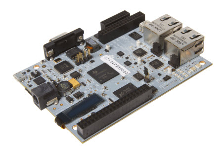
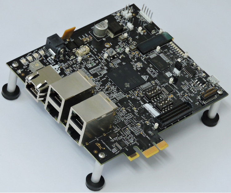
AM3359 Industrial Communications Engine (ICE)
The AM3359 Industrial Communications Engine (ICE) is a development platform targeted for systems that specifically focus on the industrial communications capabilities of the Sitara AM335x ARM® Cortex™-A8 Processors
The AM335x ARM Cortex-A8 Processors integrate the Programmable Real-time Unit (PRU) that has been architected to implement the real-time communication technologies used in a broad range of industrial automation equipment. It enables low foot print designs with minimal external components and with best in class low power performance.
AM437x Industrial Development Kit (IDK)
The AM437x Industrial Development Kit (IDK) is an application development platform for evaluating the industrial communication and control capabilities of Sitara™ AM4379 and AM4377 processors for industrial applications.
The AM4379 and AM4377 processors are ideal for industrial communications, industrial control, and industrial drives applications. The AM437x processors integrate a quad-core Programmable Real-time Unit (PRU) that has been architected to implement the real-time communication technologies used in a broad range of industrial automation equipment. It enables low foot print designs with minimal external components and with best in class low power performance.
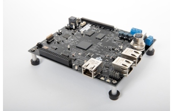
AM571x Industrial Development Kit (IDK)
The AM571x IDK is a standalone test, development, and evaluation module that enables developers to write software and develop hardware for industrial control and industrial communications applications. It has been equipped with a TI AM5718 processor and a defined set of features to allow you to experience industrial communication solutions using various serial or Ethernet based interfaces. Using standard interfaces, the AM571x IDK may interface to other processors or systems and act as a communication gateway or controller. In addition, it can directly operate as a standard remote I/O system or a sensor connected to an industrial communication network.
Note
Due to pin muxing between the optional LCD and the PRUSS1 Ethernet ports, the AM571x IDK supports two configurations. The first configuration is 4-port Ethernet + LCD. In this configuration, two Ethernet ports are provided by the CPSW, two Ethernet ports are provided by PRUSS2, and the LCD is enabled. To use this configuration, place a jumper across J51 on the board. The second configuration is 6-port Ethernet. In this configuration, two Ethernet ports are provided by the CPSW, two Ethernet ports are provided by PRUSS1, two Ethernet ports are provided by PRUSS2, and the LCD is disabled. To use this configuration, leave J51 open.
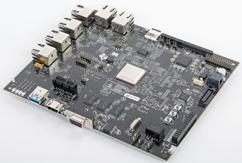
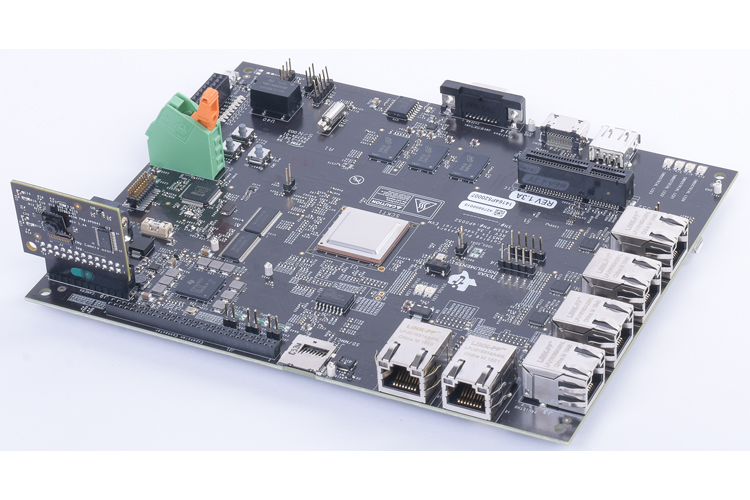
AM572x Industrial Development Kit (IDK)
The AM572x Industrial Development Kit (IDK) is a development platform for evaluating the industrial communication and control capabilities of Sitara AM572x processors for applications in factory automation, drives, robotics, grid infrastructure, and more. AM572x processors include dual PRU-ICSS (Programmable Real-time Unit for Industrial Communications) sub-systems which can be used for industrial Ethernet protocols such as Profinet, EtherCAT, Ethernet/IP, and others. The TMDXIDK5728 breaks out six ports of Ethernet, four of which can be used concurrently: 2x Gb Ethernet ports and 2x 10/100 Ethernet ports from the PRU-ICSS subsystems.
Note
Due to changes in the PRU-ICSS between silicon revisions, the PRU Ethernet firmwares provided for the AM5728 device are only meant to be used on silicon revision SR 2.0.
K2G Industrial Communication Engine (ICE)
The K2G Industrial Communications Engine (ICE) enables 66AK2Gx processor developers to immediately start development, demonstration and test of industrial communication protocols for products such as PLC, bus controllers, motion control and other real-time industrial networked applications. The evaluation module is supported by Processor SDK for RT Linux and TI-RTOS operating systems and is supplied with an SD micro card for easy boot up and out of box experience. The two PRU-ICSS subystems can be used for industrial Ethernet protocols such as Profinet, EtherCAT, Ethernet/IP, and others.
What You Get
With the PRU-ICSS Ethernet support, you get two (or four, on the AM571x IDK and K2G ICE) additional 100 Mbps Ethernet interfaces that show up just like any other Ethernet interface in Linux. These interfaces are there ‘out-of-the-box’ in the latest Linux Processor SDK when ran on any of the boards shown above. All you need to do is plug in an Ethernet cable and bring the interface up from the console (discussed below).
The current implementation does not support Ethernet switching within the PRU-ICSS. The provided PRU firmwares only support ‘dual emac’ mode in this release of the Linux Processor SDK.
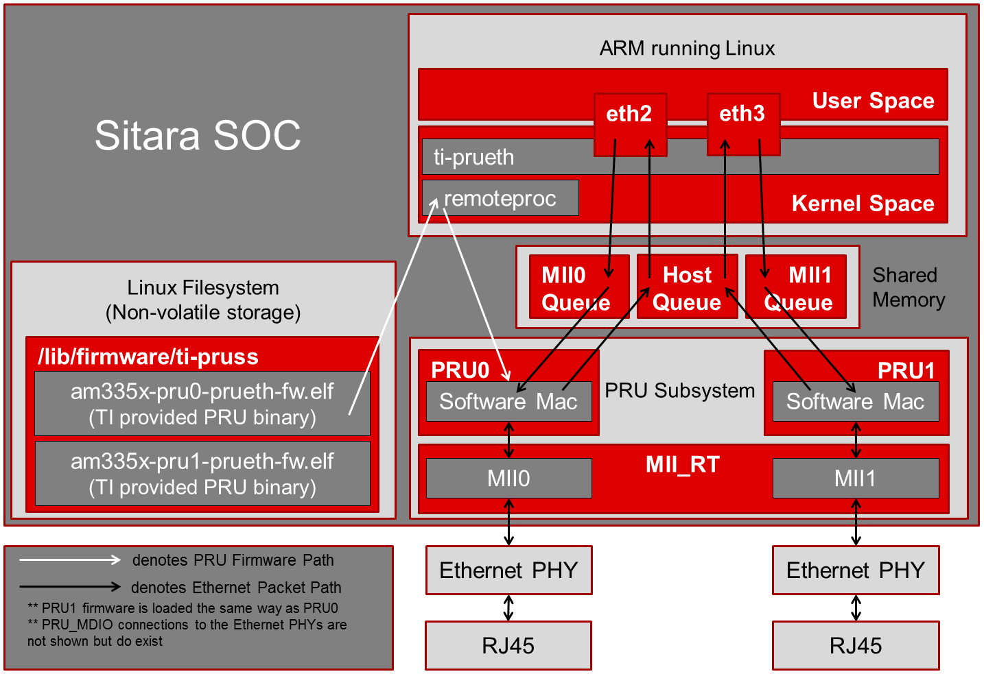
How It Works
Texas Instruments provides all of the necessary software and firmware in the Linux Processor SDK to enable the PRU-ICSS Ethernet ports. The PRU firmware binaries can be found in the /lib/firmware/ti-pruss/ folder in the filesystem. A Linux kernel networking driver is provided that can be found at <%LINUX_PROC_SDK_X_X_X_X%>/board-support/linux-x.y.z..../drivers/net/ethernet/ti/prueth.c. The required device tree modifications are also given in the dts files of the supported boards from above.
As the boards boot, the prussN_eth device tree node causes the ti-prueth driver to be probed. This probe function does several things to prepare the PRU-ICSS Ethernet ports:
- Configures the mux mode of the PRU pins for MII mode
- Requests ownership of the PRUSS memory regions from the pruss driver
- Allocates a pool of memory in OCMC SRAM for the Ethernet buffers to be passed from the PRU to Linux
- Initializes a netdev devices
- Registers the network device with Linux
At this point the Linux driver is ready for the new Ethernet interface to be started. Once the user issues the interface up command (‘ifup eth2’ for example), the emac_ndo_open function is called in the ti-prueth driver which uses the remoteproc interface to boot the PRU cores with the firmware provided in the /lib/firmware/ti-pruss/ folder of the EVM filesystem. The PRUs running this firmware, coupled with the ti-prueth Linux driver, allows up to 2 (or 4, on the AM571x IDK) additional 100 Mbps Ethernet interfaces to be exposed to the user.
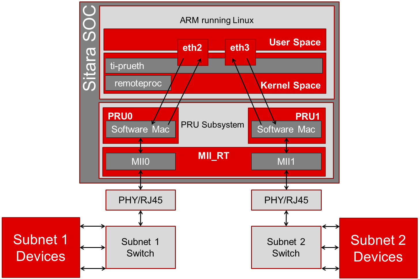
Block Diagram
Try It Out
Here are the steps needed to test out the new Ethernet interfaces:
Get your hands on one of the industrial boards
Download the Linux Processor SDK (v3.1.0.6 or higher)
Run the ‘create SD card’ script provided in the SDK to create a bootable SD card
- Plug your SD card into your Ubuntu development machine with a USB card reader
- cd <%LINUX_PROC_SDK_X_X_X_X%>/bin/
- sudo ./create-sdcard.sh
- follow the script directions to format your SD card and then install the pre-built binaries from the SDK
- for more information on creating an SD card: Processor_SDK_Linux_create_SD_card_script
Boot from the newly created SD card
Put the SD card into your board, power it on, and wait for the login prompt then type root to log in.
Note
You’ll need to clear the SPI flash on the AM3359 ICE board before you can boot from an SD card: AM3359 ICE clear SPI flash
Plug an Ethernet cable into the ports supported by the PRU-ICSS
On the AM3359 ICE there are only two Ethernet ports on the board
- In order to use the PRU-ICSS with these ports (instead of the
CPSW) you need to correctly configure both of the jumpers that
are located right next to the RJ45 jacks
- Jumpers J18 and J19 both need to be set to MII to use PRU-ICSS on the ports, you need to reboot the device for jumper changes to take effect
- If you set both of these jumpers to RMII then the CPSW will drive the ports, not the PRU-ICSS
- It is not supported to set the two jumpers to different values. Both need to be MII (PRU-ICSS) or both need to be RMII (CPSW).
- In order to use the PRU-ICSS with these ports (instead of the
CPSW) you need to correctly configure both of the jumpers that
are located right next to the RJ45 jacks
On the AM437x IDK the silkscreen says PRUETH0 and PRUETH1 for the supported PRU ports
On the AM571x IDK the silkscreen says PRU1 ETH0, PRU1 ETH1, PRU2 ETH0, and PRU2 ETH1 for the supported PRU ports
Note
On the AM571x IDK board, the pins used for PRU1 ETH0 and PRU1 ETH1 are shared with pins used for the optional LCD touchscreen. U-Boot uses jumper J51 to determine if the LCD touchscreen should be enabled or not. If J51 is closed (jumper is present across the two pins), then U-Boot will load a device tree that enables the LCD touchscreen and disables PRUSS1 Ethernet ports. This means that only PRU2 ETH0 and PRU2 ETH1 will be supported if jumper J51 is closed. If J51 is open (jumper is not present across the two pins), then U-Boot will load a device tree that enables all four PRUSS Ethernet ports, two from PRUSS1 and two from PRUSS2. In this mode, the LCD touchscreen is disabled.
On the AM572x IDK the silkscreen says PRU2 ETH0 and PRU2 ETH1 for the supported PRU ports
On the K2G ICE the supported PRU ports are the two stacked RJ45 connectors
Bring up the PRU Ethernet interface in Linux
Depending on your board and the contents of your /etc/networking/interfaces file, the PRU-ICSS Ethernet ports may already be brought up. If not:
On the AM3359 ICE type ifup eth0 to bring up Ethernet_0 and type ifup eth1 to bring up Ethernet_1
On the AM437x IDK type ifup eth1 to bring up PRUETH0 and type ifup eth2 to bring up PRUETH1
On the AM571x IDK type ifup eth2 to bring up PRU1 ETH0, type ifup eth3 to bring up PRU1 ETH1, type ifup eth4 to bring up PRU2 ETH0, and type ifup eth5 to bring up PRU2 ETH1
Note
As mentioned in the note above, jumper J51 on the board determines if two or four PRUSS Ethernet ports are supported. If J51 is closed then only two of the four interfaces listed here will be available for use.
On the AM572x IDK type ifup eth2 to bring up PRU2 ETH0 and type ifup eth3 to bring up PRU2 ETH1
On the K2G ICE type ifup eth1, ifup eth2, ifup eth3, and ifup eth4 to bring up the PRU Ethernet interfaces
If all goes well you should see the PRU-ICSS ports in the output of the ifconfig command
Network Topologies
The following network topologies are possible with the PRU-ICSS Ethernet ports.
Single Port Mode
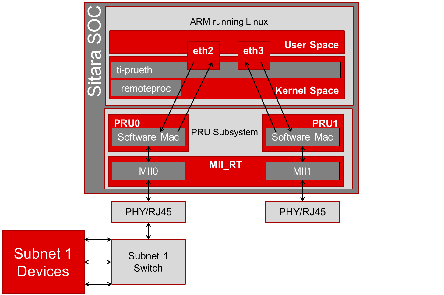
Dual MAC Mode (Gateway)
One use case made possible with two ports on the same device is to allow your device to act as a gateway between two different subnets. In this use case you just need to bring up both ports and then plug them into the two subnets as shown below.
Note
It is not a normal use case to plug both PRU-ICSS Ethernet ports into the same switch (same subnet) out-of-the-box. While it may appear to work at first, it will lead to unexpected behavior including (but not limited to) packets entering/exiting the device on the opposite port that you would expect due to ARP broadcasts and other topics that are outside the scope of this wiki page. If you would like to use both ports on the same subnet, keep scrolling to the Bonding section below.
Dual MAC Mode (Bonding)
Bonding, also called link aggregation or port trunking, is a networking feature that uses multiple Ethernet ports to provide link redundancy or an increase in throughput.
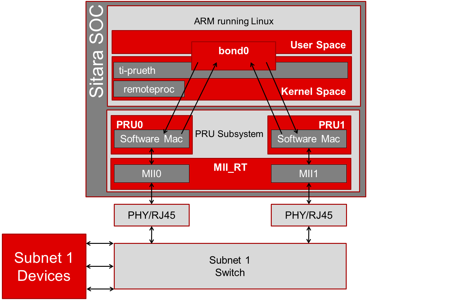
To learn even more about bonding see the Wikipedia Link aggregation page.
Steps to enable ‘active-backup’ bonding mode
While testing the below steps, I plugged both PRU-ICSS Ethernet ports into the same switch that has access to a DHCP server. During boot and bonding setup I left the cables connected. I only started unplugging cables when I was testing the bond0 interface for redundancy in the last step.
On your Linux development machine
- Enable Bonding driver support using menuconfig, rebuild Linux,
and boot your board
- The menuconfig option can be found under Device Drivers -> Network device support -> Bonding driver support’
- You can either configure the driver as built-in to the kernel (*) or as a module (M). Keep in mind that if you build the driver into the kernel that you will not be able to pass any parameters to it as it is loaded. For the example shown here, we will be using the sysfs interface to configure the bonding so it doesn’t matter which method you choose (we used the module (M) method though).
- Once Bonding driver support is enabled, rebuild your Linux
kernel and modules
- If you need help, see this page: Linux_Kernel_Users_Guide
- Now boot your board with the new kernel and bonding driver built above
On your development board console
Insert the bonding module (unless you built it into the kernel above, then it’s already there)
- modprobe bonding
Get the IP address and netmask of one of your PRU-ICSS Ethernet ports (we will need it in a second)
If the ports are already up
- ifconfig
If the ports are not up yet
ifup eth2 where 2 is the interface number for one of your PRU-ICSS Ethernet ports (this is board dependent)
ifconfig
Note
AM3359ICE: eth0 and eth1 are the PRU-ICSS Ethernet ports
AM437x IDK: eth1 and eth2 are the PRU-ICSS Ethernet ports
AM572x IDK: eth2 and eth3 are the PRU-ICSS Ethernet ports
Take down your PRU-ICSS Ethernet ports (this is necesary for bonding)
- ifconfig eth2 down
- ifconfig eth3 down
Configure bonding to use mode 1: active-backup mode
- echo 1 > /sys/class/net/bond0/bonding/mode
Configure the MII link monitoring frequency in milliseconds
- echo 100 > /sys/class/net/bond0/bonding/miimon
Bring up the bond0 interface using the IP address and netmask that you noted down from above
- ifconfig bond0 192.168.0.100 netmask 255.255.254.0 up
Bind your two PRU-ICSS Ethernet ports to the bond0 interface
- echo +eth2 > /sys/class/net/bond0/bonding/slaves
- echo +eth3 > /sys/class/net/bond0/bonding/slaves
Test out the link redundancy of the bond0 interface
- Start a ping test between your board and your development machine
- Watch the board’s console and unplug one of the Ethernet cables
- Now plug that cable back in and unplug the other Ethernet cable
- You should observe the ping program continuously receiving responses despite the cables being plugged and unplugged
- The console output will show when an interface goes does down as well as if the active interface changes
Frequently Asked Questions
Are the HSR or PRP protocols supported?
Yes! The HSR and PRP protocols are currently supported on the AM572x IDK board. To learn more about the HSR and PRP PRU firmware implementation click here. To learn more about running the protocols/firmwares while using the Linux Processor SDK click here.
HSR stands for High Availability Seamless Redundancy. This is a protocol used to support redundant networks needed for industrial applications such as factory automation, substation automation etc. The standard is defined in IEC 62439-3 clause 5.
PRP stands for Parallel Redundancy Protocol which is another redundancy protocol defined by IEC 62439-3 clause 4.
I am using the AM571x IDK, why do I only see 4 Ethernet interfaces instead of 6?
Due to pin sharing between the optional LCD and the PRUSS1 Ethernet pins, the AM571x IDK supports two different configurations: 4-port Ethernet + LCD or 6-port Ethernet with no LCD. Jumper J51 controls which configuration is selected. If J51 is closed then the 4-port + LCD configuration is selected and if J51 is open then the 6-port Ethernet configuration is selected and the LCD is disabled.
What if I want the PRU-ICSS to run a custom firmware (not Ethernet) on one of these industrial boards?
The pru_rproc driver uses the of_machine_is_compatible() function to check if the device that it is running on is compatible with one of the boards above. If it is compatible, then the pru_rproc driver loads the Texas Instruments provided PRU-ICSS Ethernet firmwares. If you would like to run your own PRU firmwares on one of the IDKs or the ICE board then you will need to modify the device tree file to remove the IDK or ICE compatibility declaration:
- AM3359 ICE board
- Remove the “ti,am3359-icev2” compatible declaration at the top of the arch/arm/boot/dts/am335x-icev2.dts file
- AM437x IDK board
- Remove the “ti,am437x-idk-evm” compatible declaration at the top of the arch/arm/boot/dts/am437x-idk-evm.dts file
- AM572x IDK board
- Remove the “ti,am5718-idk” compatible declaration at the top of the arch/arm/boot/dts/am571x-idk.dts file
- AM572x IDK board
- Remove the “ti,am5728-idk” compatible declaration at the top of the arch/arm/boot/dts/am572x-idk.dts file
Once these compatibility declarations are removed you will need to rebuild your .dtb file and place it wherever it needs to be when you reboot your board (filesystem, nfs directory, tftp directory, etc.)
Keep in mind that the PRU pin muxing on these boards is configured to bring the MII pins out of the device. Changing the pin muxing to accommodate your custom PRU firmware will be left as an exercise for the user.
What is the expected PRU-ICSS Ethernet throughput? How can I test the throughput on my setup?
The maximum bandwidth of the PRU-ICSS Ethernet ports is 100 Mbps. The observed throughput that I have achieved consistently is around 94 Mbps using TCP or UDP and testing with iperf. Here are the commands needed to test for yourself (this assumes you’ve followed the steps on this page to get your PRU-ICSS interface up and running already):
- Make sure that your board and your Linux development machine can ‘see’ each other on the network (I connect both to the same switch and allow them to use DHCP to acquire IP addresses on the same network)
- Use ifconfig on both your Linux development machine and your
board and note down each IP address
- For the purposes of this example I will use 192.168.0.105 as the Linux host IP and 192.168.1.110 as the board’s IP
- Testing TCP transmit throughput
- Start an iperf server on your Linux development machine (sudo
apt-get install iperf if you don’t already have iperf installed)
- iperf -s
- Run the iperf client from your board to connect to the iperf
server you just started
- iperf -c 192.168.0.105
- You should see your board connect to the server and a few seconds
later both the server and the client will output the Bandwidth
achieved
- For me this is output is around 94 Mbits/sec
- Quit the iperf server that is running on your Linux development
machine
- Ctrl + c
- Start an iperf server on your Linux development machine (sudo
apt-get install iperf if you don’t already have iperf installed)
- Testing TCP receive throughput
- Use the same procedure as provided for testing TCP transmit throughput except swap the commands on the two devices (iperf -s from the board and iperf -c 192.168.1.110 from the Linux development machine)
- Testing UDP transmit throughput
- Start a UDP iperf server on your Linux development machine
- iperf -s -u
- Run a UDP iperf client from your board and specify the bandwidth
you’d like to achieve
- iperf -c 192.168.0.105 -u -b 100M
- Once again my results are around 94 Mbit/sec
- Quit the iperf server that is running on your Linux development
machine
- Ctrl + c
- Start a UDP iperf server on your Linux development machine
- Testing UDP receive throughput
- Use the same procedure as provided for testing UDP transmit throughput except swap the commands on the two devices (iperf -s -u from the board and iperf -c 192.168.0.110 -u -b 100M from the Linux development machine)
Is flow control supported in the PRU-ICSS Ethernet ports?
Are multicast and VLAN filtering as well as storm prevention supported in the PRU-ICSS Ethernet ports?
Yes, the Dual EMAC firmware supports per port multicast and VLAN filtering, as well as network storm prevention. These features also exist in the HSR/PRP firmware and are detailed for both HSR/PRP and Dual EMAC here: HSR/PRP Linux Software
How do I check the link status and hardware statistics of my PRU-ICSS Ethernet ports?
You can use the ethtool utility:
- ethtool eth2 (for link status)
- ethtool -S eth2 (for hardware statistics)
3.6.4. Linux User Space
3.6.4.1. ICSS_EMAC
Overview
The ICSS_EMAC (Industrial Communications SubSystem Ethernet Media Access Controller) driver provides APIs to transmit and receive packets with a firmware based Ethernet switch that has been implemented on TI’s PRU-ICSS (Programmable Real-Time Unit Subsystem and Industrial Communication SubSystem) 32-bit RISC cores. The user space ICSS-EMAC driver has the same software architecture and features as the RTOS ICSS-EMAC, but implements the memory access and interrupt handling through Linux Userspace I/O (UIO) driver.
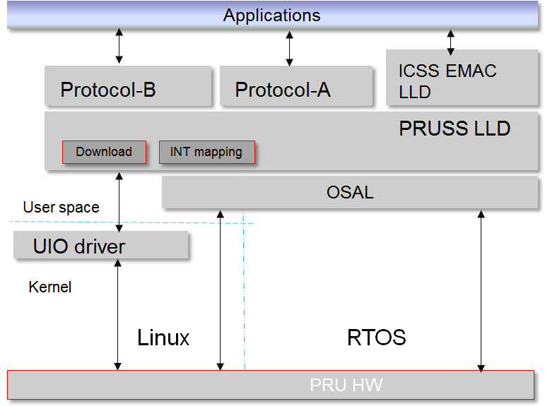
Software Stack
The picture below illustrates the software stack of ICSS-EMAC Linux user space. Majority of the upper layer components are common between RTOS and Linux user space, with the difference on Linux OS with the UIO driver vs. RTOS.
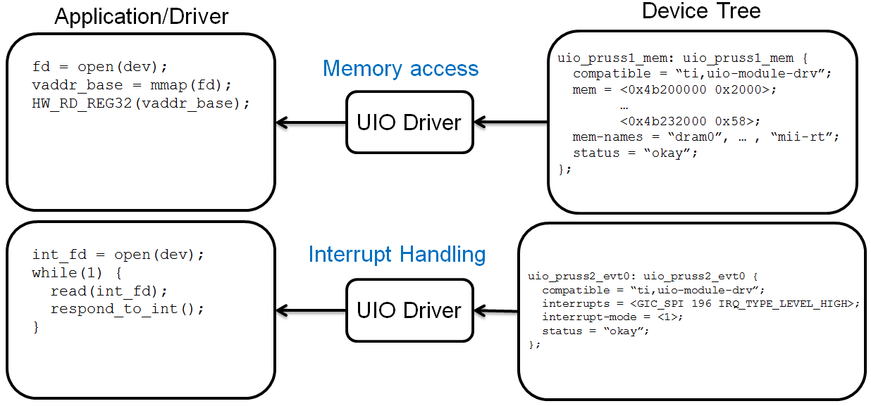
Memory Access and Interrupt Handling through UIO
While RTOS can directly access memory locations, e.g., HW_RD_REG32(0x4b220000), Linux needs memory mapping of memory regions to user space, and this is done using the UIO driver with linux file-I/O like API such as open(), close(), read(), write(), and etc.
As for the interrupt handling, RTOS registers interrupt service routines (ISRs) that are triggered when an interrupt occurs, while Linux must have a thread that waits (read()) on the file descriptor for an interrupt. Device interrupts are accessed from Linux user-space, and linux file-I/O like API such as open(), close(), read(), write(), and etc. are used here also.
The picture below shows how the memory regions and interrupts are defined in kernel device tree, and how the application/driver can map and access the memory regions, as well as handle the interrupts through the UIO driver.
Rebuild ICSS-EMAC in Linux User Space
Processor SDK Linux has packaged the pre-built binary for ICSS-EMAC LLD unit test, which can be found on filesystem at /usr/bin/icss_emacMainTest_[platform].out.
The source code of the ICSS-EMAC LLD and the unit test can be found at https://git.ti.com/keystone-rtos/icss-emac. The changes specific to Linux user space can be found by looking for the define of “__LINUX_USER_SPACE”. The files to implement the UIO based memory access and interrupt handling are placed under the test/src/armv7/linux directory.
When there is need to modify the source code of the ICSS-EMAC LLD and/or the unit test, the LLD and the unit test can be rebuilt through Yocto recipes. In order to do so, please refer to Processor SDK Building The SDK to set up the build environment, and Processor SDK Yocto Recipes to bitbake the recipes and install the newly built packages for icss-emac-lld and icss-emac-lld-test.
For example, the commands below are for rebuilding icss-emac-lld and icss-emac-lld-test for AM57xx.
MACHINE=am57xx-evm bitbake icss-emac-lld
MACHINE=am57xx-evm bitbake icss-emac-lld-test
After the bitbake commands above are successfully done, the icss-emac-lld lib and the icss-emac-lld-test binaries can found from ./build/arago-tmp-external-linaro-toolchain/work/am57xx_evm-linux-gnueabi/icss-emac-lld/<ver_number>/packages-split/icss-emac-lld/usr/lib and ./build/arago-tmp-external-linaro-toolchain/work/am57xx_evm-linux-gnueabi/icss-emac-lld-test/<ver_number>/packages-split/icss-emac-lld-test/usr/bin directories, respectively.
Running ICSS-EMAC Unit Test in Linux User Space
ICSS-EMAC unit test demonstrates loopback capability by sending dummy broadcast packets, which are then looped back with loopback cables. Unit test registers receive packet callback routine with LLD to be called for RX packet. Call back routine will extract packet received, perform simple memory comparison against packet sent for integrity check. Unit test will iterate 10 times for packet transmission and reception check. It also demonstrates time trigger send (TTS) after broadcast packets send/receive are completed. At the end of unit test, “All tests have passed” will be printed on console.
Note
Please note that time trigger send (TTS) is supported for PROCESSOR-SDK-LINUX-RT builds only due to its real-time requirement. Running TTS with PROCESSOR-SDK-LINUX builds can fail with “Packet cyclic timestamp error”.
ICSS-EMAC user space driver and unit test are now supported on multiple TI platforms, including
- AM335x ICE V2
- AM437x IDK
- AM571x IDK
- AM572x IDK
- K2G ICE
The sections below describe the procedure and sample logs of running the ICSS-EMAC unit test on these platforms.
AM335x ICE V2
Before powering up the AM335x ICE V2 EVM, ensure that Pin 2 and Pin 3 of the two CPSW/ICSS Jumpers are connected. Location of these two jumpers can be found from https://processors.wiki.ti.com/index.php/AM335x_Industrial_Communication_Engine_EVM_Rev2_1_HW_User_Guide#Component_Positions.
- Plug in loopback cables to the two ICSS-EMAC ports of AM335x ICEv2 EVM
- On the filesystem under /boot directory, link am335x-icev2-pru-excl-uio.dtb as the default dtb to support PRUSS Ethernet ports, i.e., am335x-icev2-prueth.dtb.
- Reboot the EVM
- Run “icss_emacMainTest_am335x.out”
AM437x IDK
- Plug in loopback cables to the two ICSS-EMAC ports of AM4 IDK EVM
- On the filesystem under /boot directory, link am437x-idk-pru-excl-uio.dtb as the default dtb file, i.e., am437x-idk-evm.dtb
- Reboot the EVM
- Run “icss_emacMainTest_am437x.out”
AM571x IDK
First ensure that Jumper J51 is not placed. That selects between LCD function (J51 placed) and ICSS1 Ethernet (J51 removed). This also indicates that ICSS-EMAC unit test cannot run with LCD connected on the AM571x IDK board.
- Plug in four loopback cables to the four ICSS-EMAC ports
- On the filesystem under /boot directory, link am571x-idk-pru-excl-uio.dtb as the default dtb file, e.g., am571x-idk.dtb when using AM571x IDK without LCD display
- Reboot the EVM
- Run “icss_emacMainTest_am571x.out”
AM572x IDK
- Reserve core 1 for the unit test, and this can be done by adding “isolcpus=1” in uEnv.txt (under boot partition).
- On the filesystem under /boot directory, link am572x-idk-pru-excl-uio.dtb as the default dtb file, e.g., am572x-idk.dtb.
- Reboot the EVM.
- Before running the unit test, open an SSH window to the EVM.
- From console 1: run “icss_emacMainTest_am572x.out”. It will display a message and wait for the keyboard input.
- From console 2: set affinity of the unit test process to core 1: first find pid from the output log of “ps aux | grep icss”, and then run “taskset -p 2 [pid]”.
- From console 1: continue running “icss_emacMainTest_am572x.out” by pressing any keys.
K2G ICE
- Plug in loopback cables to the four ICSS-EMAC ports of K2G ICE EVM
- On the filesystem under /boot directory, link keystone-k2g-ice-pru-excl-uio.dtb as the default dtb file, i.e., keystone-k2g-ice.dtb
- Reboot the EVM
- Run “icss_emacMainTest_k2g.out”
Sample Log from AM572x IDK
- Console 1
root@am57xx-evm:~# icss_emacMainTest_am572x.out
Set core affinity before continuing the process: taskset -p 2 [pid]
Enter character:
- Console 2
root@am57xx-evm:~# ps aux | grep icss
root      1425  0.0  0.0   1472  1068 ttyS2    S+   18:24   0:00 icss_emacMainTest_am572x.out
root      1427  0.0  0.0   1968  1100 pts/0    S+   18:30   0:00 grep icss
root@am57xx-evm:~# taskset -p 2 1425
pid 1425's current affinity mask: 3
pid 1425's new affinity mask: 2
- Console 1 after hitting any key to continue the test:
ICSS_EMAC_testTaskPruss2: ICSS_EMAC_testPgVersion: 0x2
ICSS_EMAC_testTaskPruss2: PRU2 ETH0: LINK IS UP, eth0 state: 1, link up count: 1
packet transmission complete for packet(ICSS_EMAC_TEST_PRU2ETH0): 0
ICSS_EMAC_testTaskPruss1(PRU2 ETH0): received pkt: 0
packet transmission complete for packet(ICSS_EMAC_TEST_PRU2ETH0): 1
ICSS_EMAC_testTaskPruss1(PRU2 ETH0): received pkt: 1
packet transmission complete for packet(ICSS_EMAC_TEST_PRU2ETH0): 2
ICSS_EMAC_testTaskPruss1(PRU2 ETH0): received pkt: 2
ICSS_EMAC_testTaskPruss1(PRU2 ETH0): received pkt: 3
packet transmission complete for packet(ICSS_EMAC_TEST_PRU2ETH0): 3
ICSS_EMAC_testTaskPruss1(PRU2 ETH0): received pkt: 4
packet transmission complete for packet(ICSS_EMAC_TEST_PRU2ETH0): 4
ICSS_EMAC_testTaskPruss1(PRU2 ETH0): received pkt: 5
packet transmission complete for packet(ICSS_EMAC_TEST_PRU2ETH0): 5
ICSS_EMAC_testTaskPruss1(PRU2 ETH0): received pkt: 6
packet transmission complete for packet(ICSS_EMAC_TEST_PRU2ETH0): 6
packet transmission complete for packet(ICSS_EMAC_TEST_PRU2ETH0): 7
ICSS_EMAC_testTaskPruss1(PRU2 ETH0): received pkt: 7
packet transmission complete for packet(ICSS_EMAC_TEST_PRU2ETH0): 8
ICSS_EMAC_testTaskPruss1(PRU2 ETH0): received pkt: 8
packet transmission complete for packet(ICSS_EMAC_TEST_PRU2ETH0): 9
ICSS_EMAC_testTaskPruss1(PRU2 ETH0): received pkt: 9
ICSS_EMAC_testTaskPruss2: PRU2 ETH1: LINK IS UP, eth0 state: 1, link up count: 2
packet transmission complete for packet(ICSS_EMAC_TEST_PRU2ETH1): 0
ICSS_EMAC_testTaskPruss1(PRU2 ETH1): received pkt: 10
packet transmission complete for packet(ICSS_EMAC_TEST_PRU2ETH1): 1
ICSS_EMAC_testTaskPruss1(PRU2 ETH1): received pkt: 11
packet transmission complete for packet(ICSS_EMAC_TEST_PRU2ETH1): 2
ICSS_EMAC_testTaskPruss1(PRU2 ETH1): received pkt: 12
ICSS_EMAC_testTaskPruss1(PRU2 ETH1): received pkt: 13
packet transmission complete for packet(ICSS_EMAC_TEST_PRU2ETH1): 3
ICSS_EMAC_testTaskPruss1(PRU2 ETH1): received pkt: 14
packet transmission complete for packet(ICSS_EMAC_TEST_PRU2ETH1): 4
ICSS_EMAC_testTaskPruss1(PRU2 ETH1): received pkt: 15
packet transmission complete for packet(ICSS_EMAC_TEST_PRU2ETH1): 5
ICSS_EMAC_testTaskPruss1(PRU2 ETH1): received pkt: 16
packet transmission complete for packet(ICSS_EMAC_TEST_PRU2ETH1): 6
packet transmission complete for packet(ICSS_EMAC_TEST_PRU2ETH1): 7
ICSS_EMAC_testTaskPruss1(PRU2 ETH1): received pkt: 17
packet transmission complete for packet(ICSS_EMAC_TEST_PRU2ETH1): 8
ICSS_EMAC_testTaskPruss1(PRU2 ETH1): received pkt: 18
packet transmission complete for packet(ICSS_EMAC_TEST_PRU2ETH1): 9
ICSS_EMAC_testTaskPruss1(PRU2 ETH1): received pkt: 19

============================================================
Initiating TTS tests on ICSS_EMAC_TEST_PRU2ETH0 and ICSS_EMAC_TEST_PRU2ETH1
============================================================
TTS Port 1: Test Passed!!
Programmed Cycle Period: 800000 ns
Average Cycle Period: 799999 ns
Maximum Jitter: 40 ns
============================================================
TTS Port 2: Test Passed!!
Programmed Cycle Period: 800000 ns
Average Cycle Period: 799999 ns
Maximum Jitter: 40 ns
============================================================
TTS Port 1: Test Passed!!
Programmed Cycle Period: 800000 ns
Average Cycle Period: 800000 ns
Maximum Jitter: 40 ns
============================================================
TTS Port 2: Test Passed!!
Programmed Cycle Period: 800000 ns
Average Cycle Period: 799999 ns
Maximum Jitter: 40 ns
============================================================
TTS Port 1: Test Passed!!
Programmed Cycle Period: 800000 ns
Average Cycle Period: 799999 ns
Maximum Jitter: 40 ns
============================================================
TTS Port 2: Test Passed!!
Programmed Cycle Period: 800000 ns
Average Cycle Period: 799999 ns
Maximum Jitter: 40 ns
============================================================
TTS Port 1: Test Passed!!
Programmed Cycle Period: 800000 ns
Average Cycle Period: 800000 ns
Maximum Jitter: 40 ns
============================================================
TTS Port 2: Test Passed!!
Programmed Cycle Period: 800000 ns
Average Cycle Period: 800000 ns
Maximum Jitter: 40 ns
============================================================
TTS tests finished on ICSS_EMAC_TEST_PRU2ETH0 and ICSS_EMAC_TEST_PRU2ETH1
============================================================
Done with PRU-ICSS Instance 2 Testing

PRU-ICSS STATS for PRU2ETH0
txBcast:0xa
txMcast:0x18a88
txUcast:0x0
txOctets:0x789d80
rxBcast:0xa
rxMcast:0x18a88
rxUcast:0x0
rxOctets:0x789d80
tx64byte:0x186aa
tx65_127byte:0x0
tx128_255byte:0x0
tx512_1023byte:0x0
tx1024byte:0x3e8
rx64byte:0x186aa
rx65_127byte:0x0
rx128_255byte:0x0
rx512_1023byte:0x0
rx1024byte:0x3e8
lateColl:0x0
singleColl:0x0
multiColl:0x0
excessColl:0x0
rxMisAlignmentFrames:0x0
stormPrevCounter:0x0
macRxError:0x0
SFDError:0x0
defTx:0x0
macTxError:0x0
rxOverSizedFrames:0x0
rxUnderSizedFrames:0x0
rxCRCFrames:0x0
droppedPackets:0x0
txOverFlow:0x0
txUnderFlow:0x0
sqeTestError:0x0
TXqueueLevel:0x0
CSError:0x0


PRU-ICSS STATS for PRU2ETH1
txBcast:0xa
txMcast:0x18a88
txUcast:0x0
txOctets:0x789d80
rxBcast:0xa
rxMcast:0x18a88
rxUcast:0x0
rxOctets:0x789d80
tx64byte:0x186aa
tx65_127byte:0x0
tx128_255byte:0x0
tx512_1023byte:0x0
tx1024byte:0x3e8
rx64byte:0x186aa
rx65_127byte:0x0
rx128_255byte:0x0
rx512_1023byte:0x0
rx1024byte:0x3e8
lateColl:0x0
singleColl:0x0
multiColl:0x0
excessColl:0x0
rxMisAlignmentFrames:0x0
stormPrevCounter:0x0
macRxError:0x0
SFDError:0x0
defTx:0x0
macTxError:0x0
rxOverSizedFrames:0x0
rxUnderSizedFrames:0x0
rxCRCFrames:0x0
droppedPackets:0x0
txOverFlow:0x0
txUnderFlow:0x0
sqeTestError:0x0
TXqueueLevel:0x0
CSError:0x0

All tests have passed