6. How to Guides
6.1. Target
6.1.1. How to Recalibrate the Touchscreen
Non-Weston based Graphic System
Where is the pointercal file?
The Processor SDK Linux moves the calibration file for the touchscreen from the default location of /etc/pointercal to instead be placed at /run/media/mmcblk0p1/pointercal if the SD device is present. This was done to allow user’s to easily delete this file and force a recalibration without requiring a Linux PC to mount the file system or a serial console to access the device. In this case the pointercal file is now written to a FAT partition of the SD card, which can be mounted on both Windows or Linux.
If the pointercal file is created at /run/media/mmcblk0p1/pointercal, and there is not already a file in /etc/pointercal then the file is also copied to the old default location. This is to prevent requiring the export of the TSLIB_CALIBFILE variable as described in later sections of this document.
In the case that there is no SD card available then the pointercal file will be written to the default /etc/pointercal location.
Recalibrating by Deleting pointercal
Because the pointercal file is now written to the FAT partition of the SD card recalibrating the touchscreen can be done by simply inserting the SD card into a PC and deleting the pointercal file found on the first partition (assuming the first partition is a FAT partition). When the system is then rebooted you will be asked to calibrate the touchscreen.
Recalibrating over Serial Console
If you do have access to the serial console you can always recalibrate the touchscreen using the ts_calibrate command as normal. However, in this case if you already have a pointercal file on the SD card you will need to export the TSLIB_CALIBFILE variable to point to that location before you run ts_calibrate. i.e.
target# export TSLIB_CALIBFILE=/run/media/mmcblk0p1/pointercal
target# ts_calibrate
NOTE: If you have Matrix or any other GUI application already running you should stop that application (How to Stop Matrix) before running ts_calibrate so that you can see the calibration screen.
Exporting TSLIB_CALIBFILE
The environment variable TSLIB_CALIBFILE is used by the tslib package to indicate the location of the pointercal file. The default value for TSLIB_CALIBFILE is /etc/pointercal. If you are writing a program that uses tslib you should make sure that you export TSLIB_CALIBFILE to point to the location of your pointercal file (as indicated in the previous section), or that you place a copy of the pointercal file at the default /etc/pointercal location.
Weston based Graphic System
Where is the ws-calibrate.rules file?
The Processor SDK Linux moves the Weston calibration file for the touchscreen from the default location of /etc/udev/rules.d/ws-calibrate.rules to instead be placed at /run/media/mmcblk0p1/ws-calibrate.rules if the SD device is present. This was done to allow user’s to easily delete this file and force a recalibration without requiring a Linux PC to mount the file system or a serial console to access the device. In this case the ws-calibrate.rules file is now written to a FAT partition of the SD card, which can be mounted on both Windows or Linux.
If the ws-calibrate.rules file is created at /run/media/mmcblk0p1/ws-calibrate.rules, and there is not already a file in /etc/udev/rules.d/ws-calibrate.rules then the file is also copied to the old default location.
In the case that there is no SD card available then the ws-calibrate.rules file will be written to the default /etc/udev/rules.d/ws-calibrate.rules.
Recalibrating by Deleting ws-calibrate.rules
To trigger touchscreen re-calibration, both ws-calbration.rules files need to be deleted. The ws-calbration.rules file which is now written to the FAT partition of the SD card can be deleted by simply inserting the SD card into a PC and deleting the ws-calbration.rules file found on the first partition (assuming the first partition is a FAT partition) and we also need to delete /etc/udev/rules.d/ws-calibrate.rules from the filesystem. After both ws-calibration.rules files are removed, you will be asked to calibrate the touchscreen when the Weston is launched at the first time or relaunched by issuing “/etc/init.d/weston start” command at the console.
Alternatively, you may delete the above listed files directly from the EVM’s console by issuing the following commands at EVM’s Linux prompt, and reboot the EVM to allow recalibration of the LCD.
rm /etc/udev/rules.d/ws-calibrate.rules
rm /run/media/mmcblk0p1/ws-calibrate.rules
reboot
6.1.2. SDK File System Optimization/Customization
Purpose
The purpose of this article is to explain the file systems that are delivered as part of the Processor SDK Linux and how those file systems can be modified to customize them for your use case. The tools discussed in this article are installed by default in the Processor SDK Linux file system for your convenience.
Pre-built File Systems
The Processor SDK Linux ships with two default file systems. They are:
- base-rootfs-<machine>.tar.gz - This file system is the simple file system that forms the base of the SDK file system. It has some basic utilities installed but is intended to be rather small and light weight.
- tisdk-rootfs-<machine>.tar.gz - This file system is created by taking the base file system and adding all the additional SDK components such as 3D graphics, matrix, profiling tools, etc. It is a larger file system but is meant to have most of the tools developers would need when working with TI processors.
Both of these file systems contain the opkg package manager and can be used as a starting point for system optimization as discussed in the next sections.
The Basics of OPKG
opkg - list commands
opkg is the package manager used in the SDK file systems to install and remove packages. You can get a list of the full commands supported by opkg by running the following command on the target device:
target# opkg
opkg - list installed packages
To the list of packages are part of the file system and the version of each package you can run the following command on the target device:
target# opkg list-installed
Note
This list only contains information about packages that were installed using the package manager. Applications that were built and copied to the file system and not installed as a .ipk package are not tracked by opkg
opkg - list package contents
Sometimes it is useful to know what files a package has installed. To do this you can use the following command:
target# opkg files <pkgname>
Where <pkgname> is the name of the package as given in the opkg list-installed output. This command will produce a list of all the files on the file system that belong to the given package.
opkg - find a file owner
Sometimes you may find a file on the target file system that you want to remove, or just know where it came from. In this case you can use the following command:
target# opkg search <file>
This command will find which package installed the given file. This may be useful later when you want to remove an particular file because this command can help you find the package to remove.
opkg - finding dependencies
Sometimes when you want to remove a package it is useful to find out what other packages depend on the package you are removing. While the opkg remove command will tell you the immediate dependencies you can find the longer list of dependencies using:
target# opkg whatdepends <pkgname>
This command will print the list of packages the depend on the package you entered, as well as the packages that depend on those packages, and so forth.
Removing Packages
One of the simplest ways to modify the contents of the file system is to use the opkg utility to remove packages (or install if you have pre-built packages). Removing a package is often as simple as:
target# opkg remove <pkgname>
However, sometimes a package is a DEPENDENCY of another package. In this case you have the following options:
- Use the –force-depends option
- This option will force the removal of the package but will leave any packages that depend on this package installed. This can be useful in the case that you want to remove a particular package, but that package is depended on by some other package that you do not want removed.
- Use the –force-removal-of-dependent-packages option
- This option will go up the dependency list and remove all packages in the dependency chain. You should check all the packages being removed to make sure they are indeed packages you want to remove and do not contain other files you want.
- Remove the individual packages that depend on this package first
- This way you can control exactly which dependent packages are removed and which are left in place.
target# opkg remove --force-removal-of-dependent-packages <pkgname>
Note
opkg will print the packages that depend on the package being removed. It is usually a good idea to use the opkg files command for the packages that depend on the one being removed so that you can make sure that no files you really want to keep are going to be removed.
Note
You can also use the whatdepends option discussed above to see the dependency list for a package
By using the opkg remove command in conjunction with the commands for listing packages, finding file owners, and listing package contents, you can quickly strip down a full file system into something smaller and more optimized for your use case. However, once a package is removed it cannot currently be re-installed without generating the .ipk file to install it.
Adding Applications
In most cases installing additional applications can be as simple as copying the the binary executable to the file system. However, if you have built your own .ipk packages you can use opkg to install those ipks into the target file system. One major advantage of using the package manager is the ability to track the package and it’s content with the opkg package manager. More details will be coming about how to build your own packages, but for now please refer to Building the SDK and this link to learn more about building custom file systems with Arago.
6.1.3. How to add a JVM
Introduction
This article shows the steps necessary to add an Oracle Hotspot Java Virtual Machine (JVM) to your Sitara SDK. Due to the licensing of this JVM, it can not be delivered with the Sitara SDK. You must download it and install it separately. Customers wishing to evaluate this JVM should also investigate and evaluate the Oracle Hotspot license. You must download the JVM that matches the ABI of the SDK version you are using. (see Download for more information)
Download the JVM
- Select the version that matches your processor.
- ARMv7 for Cortex-A8
- ARMv5 for ARM9
- Select a version that matches the ABI of the SDK, either hard float
or soft float.
- Hard float - for SDK 06.00 and later
- Soft float - for SDK 05.07 and earlier
- Select the headless version. To use the full capabilites of the headful version, you need to have some windowing support like X11 in your filesystem. Sitara SDK currently does not support X11. However if you download the headful version, you can run Caffeinemark, but you will not be able to use the display capabilites.
- Before you can download, you have to agree to their license and click through a few required inputs.
- Download the JVM
This can be done from the Oracle link:
For soft float: https://www.oracle.com/technetwork/java/embedded/downloads/javase/index.html
For Early Access Release for the Hard float ABI: link: https://jdk8.java.net/download.html
Install the JVM
Untar the JVM to your target filesystem. It can go anyplace you want. For this wiki we are assuming you install at /home/root
- See this article if you’re not sure how to untar
Setup your PATH environment variable on your target filesystem to point to the location of the “java” executable which can be found in the “bin” directory located in the root directory of the JVM.
to automate setting of the PATH, add the following line to the file: /etc/profile (NOTE: for this example version 1.7.0_04 was used, your version may be different)
PATH=$PATH:/home/root/ejre1.7.0_04/bin
add the above line before the following line which is found near the bottom of /etc/profile
export PATH PS1 OPIEDIR QPEDIR QTDIR EDITOR TERM
Now each time you login, your path will be automatically set up to include the “java” executable from your installed JVM. By typing “java -version”, you can verify you are setup correctly.
- you should see the JVM version displayed similar to the results below. Your version may be different depending on which one you downloaded:
root@am335x-evm:~# java -version
java version "1.7.0_04-ea"
Java(TM) SE Runtime Environment for Embedded (build 1.7.0_04-ea-b20, headless)
Java HotSpot(TM) Embedded Client VM (build 23.0-b21, mixed mode)
Running a benchmark - Pendragon Software’s CaffeineMark(tm) ver. 3.0
Caffeinemark is a Opensource benchmark which can be downloaded here: http://www.benchmarkhq.ru/cm30/info.html
Download the embedded version to your target file system.
To run:
java CaffeineMarkEmbeddedApp
Benchmark information:
- There are 6 tests associated with the Embedded version. Each tests runs for about the same amount of time and reports back how many iterations of the test could be completed in allocated time period. The higher the score the better. There is also an overall result which takes in to account all the test results.
Results for Caffeinemark running on Sitara
The following results were performed without independent verification by Pendragon Software and Pendragon Software makes no representations or warranties as to the result of the test
AM37x EVM running with a MPU clock rate of 1GHz
AM37x EVM achieved a CaffeineMark(tm) 3.0 score of 16046 running on linux-2.6.37
root@am37x-evm:~/ttt# java CaffeineMarkEmbeddedApp
Sieve score = 13991 (98)
Loop score = 29054 (2017)
Logic score = 24167 (0)
String score = 8910 (708)
Float score = 10483 (185)
Method score = 18603 (166650)
Overall score = 16046
AM335x EVM running with a MPU clock rate of 720MHz
AM335x EVM achieved a CaffeineMark(tm) 3.0 score of 11172 running on linux-3.2
root@am335x-evm:~/ttt# java CaffeineMarkEmbeddedApp
Sieve score = 9747 (98)
Loop score = 20384 (2017)
Logic score = 17383 (0)
String score = 6047 (708)
Float score = 7091 (185)
Method score = 13136 (166650)
Overall score = 11172
AM180x EVM running with a MPU clock rate of 300MHz
AM180x EVM achieved a CaffeineMark(tm) 3.0 score of 2213 running on linux-2.6.37
root@am180x-evm:~/CaffieneMark# ../ejre1.7.0_06/bin/java -version
java version "1.7.0_06"
Java(TM) SE Embedded Runtime Environment (build 1.7.0_06-b24, headless)
Java HotSpot(TM) Embedded Client VM (build 23.2-b09, mixed mode)
root@am180x-evm:~/CaffieneMark# ../ejre1.7.0_06/bin/java CaffeineMarkEmbeddedApp
Sieve score = 2185 (98)
Loop score = 4852 (2017)
Logic score = 3624 (0)
String score = 1533 (708)
Float score = 570 (185)
Method score = 3502 (166650)
Overall score = 2213
6.1.4. How to use a Mouse instead of the Touchscreen with Matrix
Introduction
A mouse can be used instead of touchscreen input with the Matrix GUI by following these steps. It is also possible to use touchscreen and mouse input simultaneously.
Restrictions: For AM37x and AM35x: The mouse must be connected through a USB 2.0 hub to the EVM. It must not be connected directly to the EVM.
Enable Mouse
On your Target File system, edit the file: /etc/init.d/matrix-gui-2.0 This script file will set Mouse support by default, but if it detects a touchscreen, then it will setup touchscreen support. If you comment out the touchscreen support then the default will remain mouse support. Use the ‘#’ to comment out the line below:
For Mouse support, Replace:
if [ -e /dev/input/touchscreen0 ]
then
    export QWS_MOUSE_PROTO=Tslib:/dev/input/touchscreen0
fi
with
#   if [ -e /dev/input/touchscreen0 ]
#   then
#       export QWS_MOUSE_PROTO=Tslib:/dev/input/touchscreen0
#   fi
To Enable both Mouse and touchscreen simultaneously: Replace
export QWS_MOUSE_PROTO=Tslib:/dev/input/touchscreen0
with
export QWS_MOUSE_PROTO="Tslib:/dev/input/touchscreen0 Auto"
Warning: If you enable both, the touchscreen now requires a double touch instead of a single touch.
Kernel
The Kernel has been configured to enable mouse support in your SDK, so this step is not necessary if you are using the SDK.
If you have built your own kernel: The kernel must be configured to include the PS/2 mouse support. To verify this, run the menuconfig utility.
Device Drivers —> Input device support —> <*> Mouse interface
Device Drivers —> Input device support —> <*> Mice —>
If mouse support is not already included in the kernel, enable the above two configuration by typing ‘y’ and rebuild the kernel. You can find instructions for rebuilding kernel here:
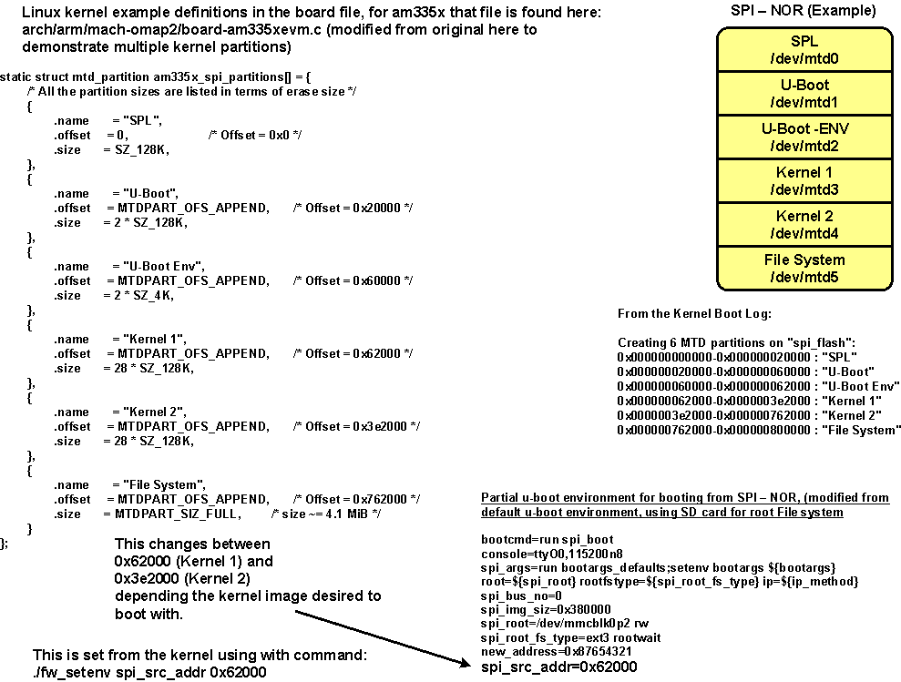
6.1.5. Update U-Boot Environment Variables stored in SPI Flash from Linux
Purpose
The purpose of this article is to demonstrate how the U-Boot Environment variables stored in SPI Flash can be accessed from a Linux command line using a tool provided from U-Boot.
Assumptions
- This example is based on the AMSDK, AM335x GP EVM and the User is has the latest version of the AMSDK installed
Summary/Checklist
- Build(Cross Compile) fw_printenv/fw_setenv U-Boot Tool provided with U-Boot source in the AMSDK
- Prepare configuration file for U-Boot Tool fw_printenv/fw_setenv
- Load fw_printenv/fw_setenv into target file system
- Test fw_printenv/fw_setenv tool
Overview
To access the environment variables from Linux one of the tools from u-boot must be cross compiled and copied into the file system. This tool is located in the board-support/u-boot<version>/tools/env directory of the latest AMSDK.
Build(Cross Compile) fw_printenv/fw_setenv U-Boot Tool
Please note that all paths are refereneced to the u-boot source within the AMSDK, ti-sdk-am335x-<version>/board-support/u-boot<version>.....
Prior to building the The flag in board-support/u-boot<version>/tools/envfw_env.h “HAVE_REDUND” must be undefined as only a single env partition has been defined in the AMSDK SPI MTD partitioning.
Please note that the CROSS_COMPILE flag is not used by the u-boot makefile here, the HOSTCC= variable must be set.
host# make HOSTCC=arm-arago-linux-gnueabi-gcc env
This command is issued from the top of the u-boot source directory. Please be sure to see that the cross compiler was actually called and not just gcc.
Prepare configuration file for U-Boot Tool fw_printenv/fw_setenv
After building the executable a configuration file must be created and placed into a specific directory that is called in fw_env.h in the board-support/u-boot<version>/tools/env directory. The default location for the configuration file (fw_env.config) is /etc/.
/dev/mtd2 0x0000 0x2000 0x1000
Load fw_printenv/fw_setenv into target file system
This creates the executable fw_printenv, this file must be copied into the target file system, place in /sbin or the user’s directory.
You must copy fw_printenv to fw_setenv to be able to set variables. The program detects the name it was called as and sets the context it will run in.
Test fw_printenv/fw_setenv tool
The executable fw_printenv will dump the entire environment space, individual variables can be read by:
target# ./fw_printenv autoload
To set an environment variable use fw_setenv . This example will set the variable autoload to no, use fw_printenv to read back the change.
target# ./fw_setenv autoload no
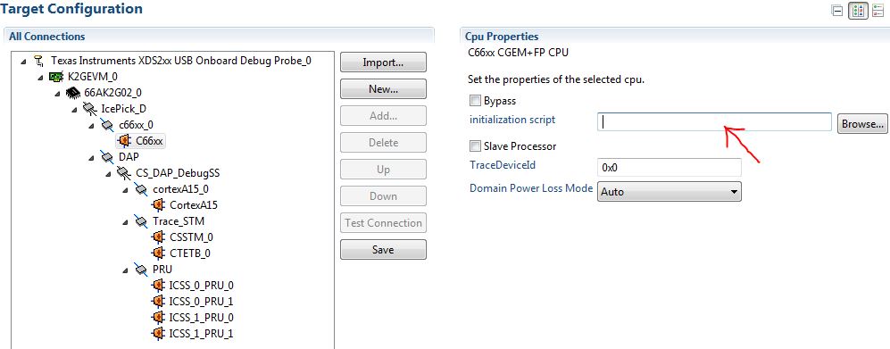
6.1.6. Taking the C66x Out Of Reset with Linux Running on the ARM A15
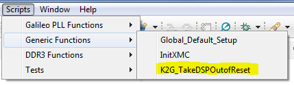
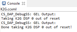
How to take the C66x DSP out of reset with Linux running on A15
This document describes the procedure to bring the C66x core out of reset after booting Linux, or at the u-boot prompt. These steps are necessary in to order to load an application on the C66x core, without interfering with the operation of Linux running on the A15.
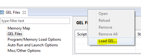
NOTE Prior to proceeding with the below instructions, please ensure that the latest Emulation package is downloaded/installed through CCS. This will ensure the GEL files in your machine has the reset routines described below.
- Once Linux has booted, launch the target configuration.
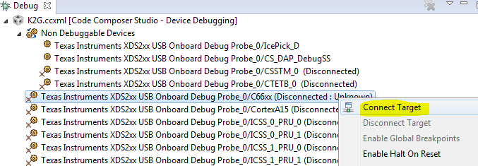
NOTE Once the DSP core is connected following the above out of reset routine, the DDR and PLL settings done by u-boot would be overwritten by what’s in the GEL. In order to avoid this, please ensure that the gel is NOT preloaded on the DSP core in the ccxml by leaving the initialization script blank.
6.1.7. How to Change dtb File
Introduction
In some scenarios, it is required to manually change the dtb file used by the target. For example, AM437X GP EVM uses LCD display by default. But it also supports HDMI display. In order to switch from LCD display to HDMI display, user needs to set the dtb file as desired.
Specify dtb File
The dtb files are located on the target filesystem under “/boot” directory. First, identify the dtb file to be used, e.g., am437x-gp-evm-hdmi.dtb for AM437X GP EVM with HDMI display.
Then, modify “uEnv.txt” on the boot partition (“/run/media/mmcblk0p1” directory on filesystem) to specify fdtfile with the desired dtb file name.
Using AM4 as the example, the default uEnv.txt has the lines below. Follow the instructions to set fdtfile so that HDMI display can be enabled. In order to go back to LCD dispaly, unset fdtfile to use the default am437x-gp-evm.dtb.
# Uncomment the following line to enable HDMI display and disable LCD display.
#fdtfile=am437x-gp-evm-hdmi.dtb
After the dtb file is changed, reboot the EVM so that the new dtb file will be used for booting the EVM.
6.1.8. How to Set Display for AM572x GP EVM
Introduction
AM572x GP EVM can have two active displays at the same time: LCD and HDMI. By default, LCD is the primary display. This wiki page describes the procedure/options of enabling/disabling the displays as well as changing the primary/secondary order of the displays.
Set Displays for AM572x GP EVM
With 0 for LCD and 1 for HDMI, the following options are available:
- omapdrm.displays=0,1: represents the original order (LCD is the primary display, while HDMI is the secondary display)
- omapdrm.displays=1,0: represents reverse order (HDMI is the primary display, while LCD is the secondary display)
- omapdrm.displays=0: only the LCD is enabled
- omapdrm.displays=1: only the HDMI is enabled
- omapdrm.displays=-1: disable all displays
To set one of the options above, stop at u-boot, and setenv for optargs. Run saveenv to save the setting if needed. For example, the
setenv below will use HDMI as the primary display.
setenv optargs omapdrm.displays=1,0
6.1.9. How to Boot Beagle Bone Black with Processor SDK Linux
Introduction
By default, BeagleBone Black EVM boots with the Debian image on eMMC. This page describes two ways to boot a BeagleBone Black EVM with Processor SDK Linux. First, create an SD card with processor SDK Linux (SDK Create SD Card Script, Creating a SD Card with Windows). Then, choose either of the two procedures below to boot with Processor SDK Linux.
Press S2 Button
With the SD card plugged in, simply keep button S2 pressed while powering up the BeagleBone Black EVM. This needs to be executed every time powering up the EVM to use Processor SDK Linux.
Erase eMMC
With the SD card plugged in, stop at uboot. Then run the following two commands to erase eMMC.
mmc dev 1
mmc erase 100 2800
With eMMC erased (one-time change), the booting falls back to use the SD card. Power cycle the BeagleBone Black EVM to boot with Processor SDK Linux.
6.2. Host
6.2.1. How to Develop with 3D Graphics
Please refer to Graphics & Display chapter for details.
6.2.2. How to Develop accelerated Multimedia using GStreamer on AM57xx
Please refer to Multimedia chapter for details.
6.2.3. How to Build a Ubuntu Linux host under VMware
Warning
This content is no longer maintained. It has been left here in case it can help someone, but it will not be maintained and will eventually move out of date. If you choose to use a Virtual Machine to host your development version of Linux on a PC, the VM provider will provide up to date information that is better and more complete than what we’ve provided here.
Introduction
This guide demonstrates how to get a virtual Ubuntu Linux machine running with VMware under Windows 7. Please use only the 32-bit Ubuntu 14.04 release as this is what is called an LTS (Long Term Support). There are SDK scripts that will be checking for this release identity.
Requirements:
- Windows 7 host with internet connection, at least 1G of RAM and 40G of free hard drive space.
The instructions here are for setting up a 40G virtual machine. The entire 40G is not taken at once, but as the machine is used and software is installed, the machine can grow and take up as much as 40G.
Download the Ubuntu 14.04 LTS ISO image
Get the Ubuntu 14.04 LTS CD ISO image from: https://releases.ubuntu.com/14.04/. Select PC (Intel x86) desktop CD under the Desktop CD section.
Click download and the follow instructions to download and save the ISO image somewhere. Remember where you save this - you will need the ISO soon!(CD image).
Download VMware and install
Get VMware from: https://www.vmware.com
Vmware Player is a free download from the website and enables the user to create an entire virtual machine from scratch using just the ISO image downloaded from Ubuntu. It is necessary to sign up for an account at VMware in order to get to the download areas. The general steps to getting VMware are as follows:
- Login to the vmware website
- Select VMware Player from the products menu
- Follow the steps to download VMware Player
NOTE - We have tested with v7.0.0 with no known issues. As of Feburary, 2015, v7.0.0 is the latest version.
- Run the executable to install VMware
- Accept license and all default settings.
Create a New Virtual Machine with VMware
Before starting a new installation it is assumed that the Windows host has a proper internet connection to a DHCP server and that the Windows host has enough hard drive space for the new virtual machine.
The following steps are performed with VMware 7.0.0. The exact steps with other versions may vary slightly
- Start VMware.
- From the File menu select “Create a New Virtual Machine...”
- Choose to install the operating system later. Click “Next”.
- Select Linux as the “Guest Operating System” and then choose Ubuntu as the “Version”. Click “next”.
- Provide a “Virtual machine name” and “Location” where the machine will be stored on the Windows host. The defaults are fine here. Click “Next”.
- For “Maximum disk size (GB)” it is good to start with 40G if possible. This means that it will take up 40G on the Windows host. Make sure that the Windows host has at least this much before proceeding. It is also a good practice to tell VMware to split the virtual disk into 2G files. This will makes the image easier to copy and transport if necessary. Click “Next”.
- Click “Finish” to complete the creation of the virtual machine.
The machine name will now be listed under the home page of VMware. It is necessary to modify some machine settings before playing the machine for the first time. Select the machine in the home page and then click on “Edit virtual machine settings” on the right.
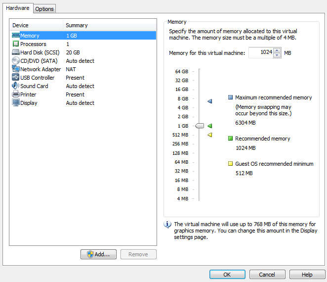
Click on CD/DVD and change the connection to “Use ISO image file”. Click on “Browse...” and select the Ubuntu ISO image file that was previously downloaded. Click on Network Adapter and change the Network connection to “Bridged” and then check the box to “Replicate physical network connection state”.
Adding a serial port to the virtual machine
If you plan to use a serial terminal application, a serial port must be added to the virtual machine. This port must be a physical serial port which exists on the host PC. Click on “Add...” and select “Serial Port”. Click “Next”. Choose “Use physical serial port on host”. Click “Next”. Click Finish. Click “Ok”.
Since this is a physical port on the host PC, it cannot be used by the host PC and the virtual machine at the same time. When the virtual machine is started, the serial port will be unavailable for use by the host PC. If the serial port is being used at the time that the virtual machine is started, the virtual machine will not be able to access the serial port after it is booted up. So if you want the virtual machine to gain control of the physical serial port of the host PC, there can not be any application like hyperterminal or teraterm running on the host PC at the time that the virtual machine is started.
Further instructions for using the serial port with minicom inside of Ubuntu are here.
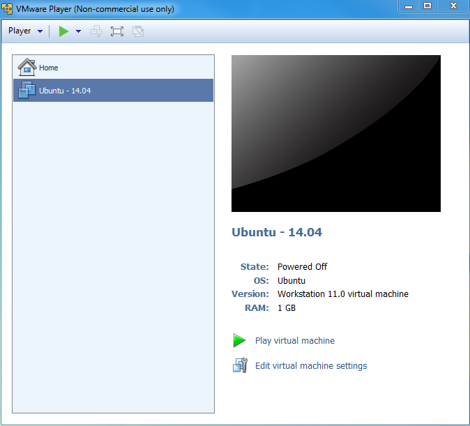
Now click on “Play virtual machine”. Since this is the first time starting the machine and the Ubuntu ISO image is in the virtual CD drive, the Ubuntu OS will install itself in the virtual machine.
Click through the Ubuntu installation, making the appropriate choices as you go. This will help with SDK installation scripts.
After the machine reboots into Ubuntu it is helpful to take the Ubuntu ISO out of the virtual CD drive. Click on the VM menu and select “Settings...”. Click on CD/DVD and change the connection from “Use ISO image file” to “Use physical drive”. The actual drive letter can be selected from the drop down list. If there is no physical drive on the host machine, the CD/DVD device can be simply removed from the machine.
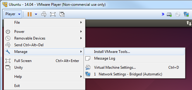
Install VMware Tools
VMware tools is a very useful addition to VMware. It allows you to resize the VMware screen ,cut-and-paste of text and drag and drop files from the Ubuntu machine to and from the Windows host.
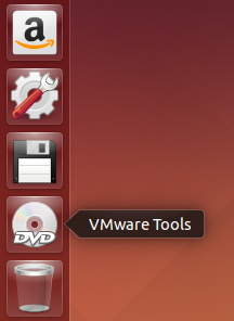
Within the virtual machine window click the Player -> Manage -> Install VMware Tools
The VMware tools are contained in an ISO image that VMware will automatically mount. This drive will show up on the Ubuntu desktop as if it were a disk in a DVD drive.
There will be a single tarball on the drive named VMwareTools-9.9.0-2304977.tar.gz (or with a slightly different version number). Extract the tarball somewhere in your /home/<user> directory. You will see that a vmware-tools-distrib folder was created and a file name vmware-install.pl inside. Execute vmware-install.pl to install VMware Tools. The Perl script must be executed as a super-user. This is done in Ubuntu by pre-pending the command with “sudo”. When prompted for a password, enter the password for the user account. In Ubuntu, there is no “root” account. However, the first user account created when Ubuntu is installed can become a super-user with the “sudo” command. Select all of defaults during installation of VMware Tools.
An example is shown below.
sitara@sitara-virtual-machine:~$ cd
sitara@sitara-virtual-machine:~$ tar -xzvf /media/sitara/VMware\ Tools/VMwareTools-9.9.0-2304977.tar.gz
sitara@sitara-virtual-machine:~$ sudo ./vmware-tools-distrib/vmware-install.pl
Confirming a Valid Network Connection
After logging into the machine for the first time, bring up a terminal window. This can be found under the Applications menu in Ubuntu. Applications –> Accessories –> Terminal. Type pwd in this terminal. This should return /home/<user>. Now type ifconfig. This should return information about the network connection. Under eth0 the IP address should be similar (but not the same) as the IP address owned by the Windows host.
sitara@sitara-virtual-machine:~$ ifconfig
eth0 Link encap:Ethernet HWaddr 00:0c:29:da:a8:6e
inet addr:128.247.107.65 Bcast:128.247.107.255 Mask:255.255.254.0
inet6 addr: fe80::20c:29ff:feda:a86e/64 Scope:Link
UP BROADCAST RUNNING MULTICAST MTU:1500 Metric:1
RX packets:759 errors:0 dropped:0 overruns:0 frame:0
TX packets:32 errors:0 dropped:0 overruns:0 carrier:0
collisions:0 txqueuelen:1000
RX bytes:62873 (62.8 KB) TX bytes:4937 (4.9 KB)
Interrupt:19 Base address:0x2024

lo Link encap:Local Loopback
inet addr:127.0.0.1 Mask:255.0.0.0
inet6 addr: ::1/128 Scope:Host
UP LOOPBACK RUNNING MTU:16436 Metric:1
RX packets:12 errors:0 dropped:0 overruns:0 frame:0
TX packets:12 errors:0 dropped:0 overruns:0 carrier:0
collisions:0 txqueuelen:0
RX bytes:720 (720.0 B) TX bytes:720 (720.0 B)
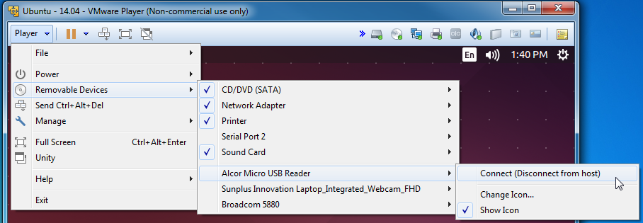
How to Read a USB SD Card Reader in VMware
6.2.4. Connect to an EVM via Telnet
Using Telnet
The initialization file (/etc/init.d/rcS) starts a telnet server. If your development host is in the same sub-net as the EVM, you can telnet to it using the IP address assigned in the U-boot environment. The following is an example from a Linux host.
$ telnet 192.168.1.10
You will be prompted for a user name and password. The user name should be root and the password should be left blank (just hit Enter).
From a Windows XP host, click the Start button, then click Run... Type telnet and click OK. This will open a telnet window.
Type “o < ip-addr >” and hit enter. Example:
Microsoft Telnet> o 128.247.107.12
Type root for the password and leave the password blank (just hit Enter)
6.2.5. How to Setup a Samba Server
Introduction
When using a Virtual machine you may share files & folders via the Share Foldr feature of that partoicular Virtual Machine. Another alternative, especially if you are using a dedicated Linux host, is to configure a Samba server on your Linux host.
Samba allows a host to interact with a Microsoft Windows client or server as if it is a Windows file and print server. In other words, if you are installing software on a Windows machine, you can easily transfer/modify files to the host machine by accessing it (the host machine) through windows.
Installing a Samba Server
1. Samba can be installed by opening a terminal. (Applications -> System Tools -> Terminal)
2. Switch to root user by typing su and entering the password you set during the install.
- On Fedora install Samba with the yum command: system-config-samba
- Open the Samba GUI (System -> Administration -> Samba).
- Configure the share
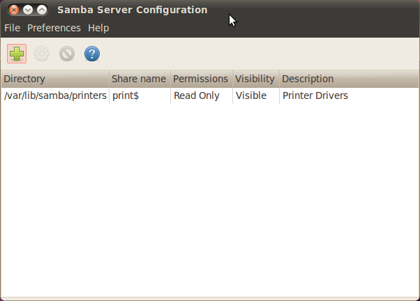
- Click on “Add Share”
- Specify the directory you want to share. For example, /home/<username>
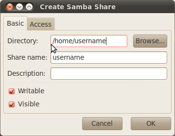
- Check both the Writable and Visable boxes
- On the “Access” tab, select the Allow access to everyone option
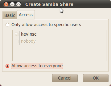
- Select “OK”
- Set up the workgroup
- From the toolbar, select Preferences -> Server Settings
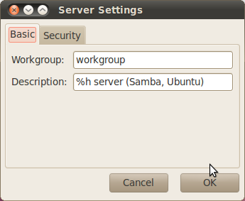
- Specify the “Workgroup” to match the workgroup on your Windows environment
- Select “OK”
- Add a user
- From the toolbar, select Preferences -> Samba Users
- Click “Add User”
- From the “Unix Username” dropdown box, select the username you set up
- In the “Windows Username” and password boxes, enter the Unix Username and password for that user, respectively.
- Select “OK”
- Turn off the firewall
- System -> Administration -> Firewall
- Select the “Disable” button
NOTE - If you are within your company’s firewall you may need to configure the network proxy.
- Enable the Samba and NFS services
- System -> Administration -> Services (NOTE - Not available in Ubuntu 10.04 LTS. However the Samba service should start automatically)
- Enable the services by browsing through the list on the left and locating nfs and smb. If they are not already enabled, enable them by clicking the “Enable” button.
- Test the configuration
- From a terminal on the Linux workstation, type the command <prompt> ifconfig and note the IP address
- From your Windows machine, go to Start -> Run and type \\<IP_ADDR> replacing <IP_ADDR> with the IP address of the Linux system
6.2.6. Boot Sequence
Introduction
This page describes the boot sequence of an OMAP3 EVM.
General Boot Sequence (Linux system)
Boot sequence (in order)
- Boot ROM
- X-loader
- U-boot
- Linux
At power-up an OMAP3 device begins booting from internal Boot ROM. This code is fixed during the manufacturing process and cannot be altered. The Boot ROM reads boot configuration pins (SW4 on the OMAP3 EVM) which tell the Boot ROM where to look for the first external bootloader. The choices include NAND, UART, and SD/MMC Card. Control is then passed to this first external bootloader called x-loader. The x-loader application is included in the Linux PSP provided by TI and can be modified by the end user. The x-loader application passes control to u-boot. U-boot is also a bootloader and is considered the second external bootloader in this case.
U-boot is the application which passes control to the Linux system. The main goal of u-boot is to retrieve the Linux kernel and provide the kernel with information about the location of the Linux filesystem. U-boot can be configured to retrieve the kernel from NAND, SD/MMC Card, UART or Ethernet (via TFTP). U-boot can also specify a root filesystem that is located in NAND (jffs2), SRAM (ramdisk), SD/MMC card (ext3 partition) or mounted over IP (NFS).
U-boot then boots the Linux kernel. The Linux kernel mounts the Linux root filesystem.
Booting TI SDK
The OMAP3 EVM which includes the TI SDK will come with an SD card. This card has been formatted and partition in such a way that the entire system comes from this card. There is a bootable FAT partition which contains x-loader (MLO), u-boot (u-boot.bin )and the Linux kernel (uImage). There is a separate ext3 partition which contains the Linux root filesystem.
A tutorial for making this SD card can be found here:
The actual file names of the binaries on the FAT partition will be as follows:
| Application or Script | Actual Filename on SD card |
|---|---|
| X-loader | MLO |
| U-boot | u-boot.bin |
| Linux kernel | uImage |
| boot script | boot.scr |
Table: Files on boot (FAT) partition of SD card
When booting from an SD card, the OMAP3 Boot ROM code will search the SD card for the filename “MLO” when looking for x-loader.
To boot from this SD card, the switches on SW4 should be set to SD/MMC boot.
- SW4 = 00100111 (high to low, i.e. SW4.1 = 1)
- 1 = “On” position on the switch
Texas Instruments X-Loader 1.45 (Mar 19 2010 - 19:44:19)
Starting X-loader on MMC
Reading boot sector

212504 Bytes Read from MMC
Starting OS Bootloader from MMC...
Starting OS Bootloader...
X-loader then passes control to u-boot. U-boot expects to find “environment variables” in NAND flash. When a board is booted for the first time or if the NAND has been erased, u-boot will indicate a Warning about bad NAND. U-boot will write a default environment that it will then use to continue the boot process.
U-Boot 2009.11 (May 06 2010 - 16:57:54)

OMAP34xx/35xx-GP ES1.0, CPU-OPP2 L3-165MHz
OMAP3 EVM board + LPDDR/NAND
I2C: ready
DRAM: 128 MB
NAND: 256 MiB
*** Warning - bad CRC or NAND, using default environment

In: serial
Out: serial
Err: serial
Read back SMSC id 0x92200000
Die ID #731c0000000000000156087c0a023021
Net: smc911x-0
Hit any key to stop autoboot: 0
The default environment is designed to boot the Linux system from the SD card, so it is not necessary to stop the boot process. And the next time that the EVM is booted the default environment will exist in NAND so the “bad NAND” warning will not be displayed.
U-boot allows the user a 2-3 seconds window to stop the boot process. Hit any key in the UART terminal application and the u-boot prompt will be displayed as shown below:
OMAP3_EVM #
There are several useful commands to remember here. To display the environment variables, type “printenv” or just “pri”.
OMAP3_EVM #
OMAP3_EVM # printenv
bootcmd=if mmc init; then if run loadbootscript; then run bootscript; else if run loaduimage; then run mmcboot; else run nandboot; f
i; fi; else run nandboot; fi
bootdelay=2
baudrate=115200
bootfile=uImage
loadaddr=0x82000000
usbtty=cdc_acm
console=ttyS0,115200n8
mmcargs=setenv bootargs console=${console} root=/dev/mmcblk0p2 rw rootfstype=ext3 rootwait
nandargs=setenv bootargs console=${console} root=/dev/mtdblock4 rw rootfstype=jffs2
loadbootscript=fatload mmc 0 ${loadaddr} boot.scr
bootscript=echo Running bootscript from mmc ...; source ${loadaddr}
loaduimage=fatload mmc 0 ${loadaddr} uImage
mmcboot=echo Booting from mmc ...; run mmcargs; bootm ${loadaddr}
nandboot=echo Booting from nand ...; run nandargs; onenand read ${loadaddr} 280000 400000; bootm ${loadaddr}
stdin=serial
stdout=serial
stderr=serial
dieid#=731c0000000000000156087c0a023021
ethact=smc911x-0

Environment size: 873/131068 bytes
OMAP3_EVM #
OMAP3_EVM # boot
## Booting kernel from Legacy Image at 80000000 ...
Image Name: Linux-2.6.32
Image Type: ARM Linux Kernel Image (uncompressed)
Data Size: 2396212 Bytes = 2.3 MB
Load Address: 80008000
Entry Point: 80008000
Verifying Checksum ... OK
Loading Kernel Image ... OK
OK

Starting kernel ...

Uncompressing Linux.....................................................................................................
.................................................. done, booting the kernel.
dm3730-am3715-evm login:
Closer Look At bootcmd
The bootcmd environment variable is a set of nested conditional statements.
bootcmd=if mmc init; then if run loadbootscript; then run bootscript; else if run loaduimage; then run mmcboot; else run nandboot; f
i; fi; else run nandboot; fi
6.2.7. Moving Files to the Target System
Introduction
This guide discusses how applications or other files can be moved to the target file system of the EVM.
File System on SD card
The SD card which comes with the TI SDK has a Linux ext3 partition that is used as the target file system. This partition is readable from a Linux host. In Ubuntu 10.04 this partition will be mounted on /media/rootfs when the card is used with an SD card reader inserted into a USB port on the Ubuntu host.
When the SD card is mounted with a card reader in the Linux host it is possible to perform “cp” commands from the host into sub-directories under /media/rootfs or just use a browser window to drag and drop the files from the host to the SD card.
Switching the SD card back and forth from the EVM to the SD card reader is time consuming during development. Using a NFS during development is the preferred method and makes moving files between the host and target trivial.
File System on Network File System (NFS)
When the target file system is served from the Linux development host machine it is trivial to move files between the host and target. The NFS directory is set up on the host machine by the SDK installer. The default location in the Ubuntu 10.04 development environment is /home/user/ti-sdk-AM3715-evm-4.0.0.0/filesystem. This could vary depending on the version of the SDK and how it was installed. An “ls -l” of this directory in the host system will show what will be the root directory of the target when it boots up.
user@U1004GT:~/ti-sdk-AM3715-evm-4.0.0.0/filesystem$ pwd
/home/user/ti-sdk-AM3715-evm-4.0.0.0/filesystem
user@U1004GT:~/ti-sdk-AM3715-evm-4.0.0.0/filesystem$ ls -l
total 60
drwxr-xr-x  2 root root 4096 2010-05-07 07:51 bin
drwxr-xr-x  2 root root 4096 2010-05-07 00:30 boot
drwxr-xr-x  2 root root 4096 2010-05-05 16:28 dev
drwxr-xr-x 24 root root 4096 2010-05-14 10:46 etc
drwxr-xr-x  3 root root 4096 2010-05-07 00:29 home
drwxr-xr-x  4 root root 4096 2010-05-07 00:30 lib
lrwxrwxrwx  1 root root   12 2010-05-13 09:35 linuxrc -> /bin/busybox
drwxr-xr-x 13 root root 4096 2010-05-14 11:01 media
drwxr-xr-x  2 root root 4096 2010-05-07 00:29 mnt
drwxr-xr-x  2 root root 4096 2010-05-05 16:28 proc
drwxr-xr-x  2 root root 4096 2010-05-07 07:51 sbin
drwxr-xr-x  2 root root 4096 2010-05-07 07:51 Settings
drwxr-xr-x  3 root root 4096 2010-05-07 00:29 srv
drwxr-xr-x  2 root root 4096 2010-05-05 16:28 sys
lrwxrwxrwx  1 root root    8 2010-05-13 09:35 tmp -> /var/tmp
drwxr-xr-x 10 root root 4096 2010-05-07 08:43 usr
drwxr-xr-x  7 root root 4096 2010-05-04 21:54 var
user@U1004GT:~/ti-sdk-AM3715-evm-4.0.0.0/filesystem$
So from the perspective of the host, the target filesystem is just a sub-directory of the host. If the file is in ./filesystem on the host, then the same file will show up in the root directory of the target after the target boots into the NFS. And if the file is in a subdirectory of ./filesystem (example ./filesystem/sub-dir) then it will show up in the /sub-dir directory of the target after the target boots into the NFS.
The top level makefile of the TI SDK supports an install target that will copy applications into the NFS of the SDK. See the README file at the top level of the SDK for information about the install target.
6.2.8. How to Flash Linux System from U-boot
Application
This article applies to Sitara SDK 4.0.1 which uses the Platform Support Package (PSP) software version 03.01.00.06
for AM35x and AM37x devices. This information is obsolete as newer software has different NAND ECC requirements.
Introduction
This guide will show how use u-boot to flash the NAND of an OMAP3 EVM (for AM37x, DM37x or OMAP35xx devices) or an AM3517EVM (for AM35x devices) with Linux system binaries.
- Assumptions:
- SD card with system binaries (x-loader, u-boot, Linux kernel) on boot partition
- Linux root filesystem in rootfs partition of SD card or root filesystem available via NFS
Caution
The procedures here will erase the NAND flash of the EVM. This includes all u-boot environment variables. Use the “printenv” command (or just “pri”) in u-boot to print a complete list of environment variables. Copy and paste these to a text file for safe keeping.
Boot EVM into SD/MMC card boot mode
The SD card must at least have the files MLO, u-boot.bin, and uImage. All of these files can also be found in the ”./psp/prebuilt-images” directory in the Sitara SDK installation (with names that include the platform name and software revision info). The MLO file is simply a re-named copy of the file x-load.bin.ift that is produced by rebuilding x-loader and signing the file. When the board is booted in SD/MMC card boot mode, the ROM code looks specifically for the file with the name MLO as the primary bootloader.
To boot from this SD card, the boot switches should be set to SD/MMC boot:
For Mistral OMAP EVM (AM37x, DM37x or OMAP35xx devices)
Start the board and interrupt the boot process when prompted by hitting any key in the UART terminal application:
Texas Instruments X-Loader 1.45 (Mar 19 2010 - 19:44:19)
Starting X-loader on MMC
Reading boot sector

212504 Bytes Read from MMC
Starting OS Bootloader from MMC...
Starting OS Bootloader...
U-Boot 2009.11 (May 06 2010 - 16:57:54)

OMAP34xx/35xx-GP ES1.0, CPU-OPP2 L3-165MHz
OMAP3 EVM board + LPDDR/NAND
I2C: ready
DRAM: 128 MB
NAND: 256 MiB
*** Warning - bad CRC or NAND, using default environment

In: serial
Out: serial
Err: serial
Read back SMSC id 0x92200000
Die ID #731c0000000000000156087c0a023021
Net: smc911x-0
Hit any key to stop autoboot: 0
OMAP3_EVM #
OMAP3_EVM #
All of the commands in this guide are performed at the u-boot prompt.
Run the u-boot commands to flash the NAND
All of the following commands are performed at the u-boot prompt.
These commands are actually a series of u-boot commands that are connected together with semicolons. The individual commands can be entered separately or simple pasted from here.
- Complete xloader write from MMC to NAND (only erases one block=128k).
mw.b 0x81600000 0xff 0x20000;nand erase 0 20000;mmc init;fatload mmc 0 0x81600000 x-load.bin.ift;nandecc hw; nand write.i 0x81600000 0 20000
- Complete uboot write from MMC to NAND (only erases two blocks=256k)
mw.b 0x81600000 0xff 0x40000;nand erase 80000 40000;mmc init;fatload mmc 0 0x81600000 u-boot.bin;nandecc sw; nand write.i 0x81600000 80000 40000
- Complete kernel write from MMC to NAND (erases 3M)
mw.b 0x81600000 0xff 0x1400000;nand erase 280000 300000;mmc init;fatload mmc 0 0x81600000 uImage;nandecc sw; nand write.i 0x81600000 280000 300000
Put the EVM in NAND boot mode
With the EVM in NAND boot mode and the images flashed in NAND as detailed above, the SD card does not need to be in the EVM at boot up. X-loader and u-boot will run from NAND. In order to also pull the Linux kernel (uImage) from NAND it will be necessary to halt the boot process and edit some u-boot environment variables.
For Mistral OMAP EVM (AM37x, DM37x or OMAP35xx devices)
Set SW4 switches #2, #4 and #6 to the ON position and all others OFF (NAND, UART3 boot order)
For LogicPD AM3517EVM (AM35x device)
Set SW7 with switches #1 thru #8 all to the OFF position. (NAND, EMAC, USB, MMC1 boot order)
- Save off the original boot command
setenv bootcmd_original ${bootcmd}
saveenv
- Create command for reading the kernel from NAND and then another command for doing the boot where the kernel is pulled from NAND and the root filesystem is from the SD/MMC card.
setenv nand_kernel 'nand read.i ${loadaddr} 280000 300000'
setenv nand_mmc_boot 'run nand_kernel;setenv bootargs ${mmcargs}; bootm'
Run this last command to actually perform the boot. And always save the environment after making changes.
saveenv
run nand_mmc_boot
Flashing the Root File System to NAND
A jffs2 file system can be copied into NAND flash. Copy the file rootfs.tar.gz to the /home/root directory on the SD Card. Boot the EVM to Linux and enter the following commands:
[prompt]$ flash_eraseall –j /dev/mtd4
[prompt]$ mount /dev/mtdblock4 /media/nand –t jffs2
[prompt]$ cd /media/nand
[prompt]$ tar xzf /home/root/rootfs.tar.gz
[prompt]$ reboot –f
The bootargs under u-boot must be altered to use this new NAND file system.
NOTE:After the reboot the board is now running in u-boot, remember to stop the autoboot sequence by typing any key. The following are u-boot commands:
setenv bootargs 'mem=128M console=ttyS0,115200n8 noinitrd root=/dev/mtdblock4 rw rootfstype=jffs2 ip=dhcp'
bootm
Mounting File System from NFS
The file system can also be mounted as a Network File System (NFS). The NFS is simply a sub-directory of the Linux host development system.
Another command can be made to pull the root filesystem via NFS. This command can be combine with the one to pull the bootloaders and kernel from NAND. (The IP address and path to the NFS is an example and should be changed by the user).
setenv serverip <ip address of nfs host>
setenv nfsargs 'setenv bootargs mem=128M console=ttyS0,115200n8 noinitrd rw ip=dhcp root=/dev/nfs nfsroot=${serverip}:/home/user/ti-sdk-AM3715-evm-4.0.0.0/rfs,nolock,rsize=1024,wsize=1024'
setenv nand_nfs_boot 'run nand_kernel;run nfsargs; bootm ${loadaddr}'
saveenv
run nand_nfs_boot
Default NAND partitioning (from x-loader)
- Block size = 0x00020000 (128k) * Page size = 0x00000800 (2k) */
6.2.9. Preventing BeagleBone board reset on JTAG Connect
6.2.10. Customizing the SDK Splash Screen
Overview
This article discusses how to customize the splash screen for the Linux SDK. The info was derived from this e2e forum post.
Steps
The “psplash” user space application is called at boot time, showing the TI logo splash screen. In order to change the displayed image, you need to first download the “psplash” package source code from here. The next steps are as follows:
1. Use the ./make-image-header.sh script included in the package to create a new header file with your new image: (you need to install libgdk-pixbuf2.0-dev library first)
./make-image-header.sh <path_to_image_file> <NAME>
Note: The <NAME> argument can be whatever you want it to be, but for the fastest approach you should use “POKY” as this is what is used by default in the psplash.c file. Unfortunately this isn’t configurable and you have to edit the file manually if you wish to use different name.
- The above command will generate the header file with the image contents (<your_logo_filename>-img.h).
- Open the psplash.c file and replace the file name in the following line at the top of the file:
#include "psplash-poky-img.h"
with
#include "<your_logo_filename>-img.h"
2.Export the needed variables and then configure and build psplash:
export CROSS_COMPILE=arm-linux-gnueabihf-
export ARCH=arm
export PATH=$PATH:$HOME/ti-sdk-am335x-evm-06.00.00.00/linux-devkit/sysroots/i686-arago-linux/usr/bin
./autogen.sh --host=arm-linux CC=arm-linux-gnueabihf-gcc
make
3. Replace the /usr/bin/psplash file in your root file system with the generated psplash file.
6.2.11. AM335x ICEv2 flash erase
Introduction
The AM3359 ICE development board from Texas Instruments comes pre-loaded with a default application in the on-board SPI flash device. In order to boot Linux from the SD card you will need to clear the SPI flash so that the boot process will fall back to SD card boot mode. The following steps will clear the SPI flash. I performed these steps with CCS v6.1.3 on a Ubuntu 14.04 host system
Steps
Mare sure pins 1 and 2 of Jumper J5 (sysboot) are connected on the board
Make sure that USB cable is connected from the AM3359 ICE board to your host development machine
Launch Code Composer Studio (CCS)
- If you do not have CCS, download it here: CCS Download
Create a target configuration file in CCS to connect to the AM3359 ICE board
NOTE If you already have a target configuration for your AM3359 ICE board you may skip this step
- Click File -> New-> Target Configuration File
- Filename : AM3359-ice-v2.ccxml. Check “Use shared location” to be
available to anyone who uses the workspace. Click Finish. A window
opens up which is to configure the connection details
- Connection: “Texas Instruments XDS100v2 USB Debug Probe”
- Device: ICE_AM3359
- Click Save
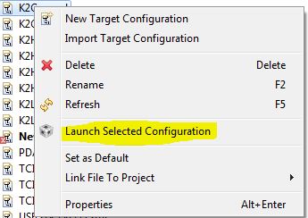
Launch your AM3359 ICE Target Configuration
- Click Window -> Show View -> Target Configurations
- Right click on the AM3359-ice-v2.ccxml file and the click Launch Selected Configuration
- This should switch your current perspective to the CCS Debug perspective. If it doesn’t, click View -> Debug to get to the CCS Debug perspective
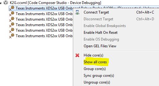
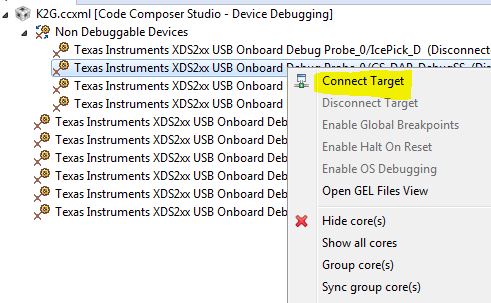
Connect the debugger to the CortexA8 core
- Right click on Texas Instruments XDS100v2 USB Debug Probe_0/CortxA8 listed in the Debug view and select Connect Target
Load the SPI flash programmer into the CortexA8 core
- Download the SPI flash programmer and unzip it: File:Isdk spi flasher.zip
- Highlight the Texas Instruments XDS100v2 USB Debug Probe_0/CortxA8 by clicking on it
- Click Run -> Load -> Load Program
- Browse to the isdk_spi_flasher.out file (that you just downloaded and unzipped) and click OK
Run the SPI flash programmer on the CortexA8
- Highlight the Texas Instruments XDS100v2 USB Debug Probe_0/CortxA8 by clicking on it
- Click Run -> Resume
At this point the SPI flash programmer is running on the CortexA8 and we just need to follow the prompts to clear the flash
- If it isn’t opened already, open the Console view by clicking Window -> Show View -> Console
- The program will give you the following prompts, type the
responses and press Enter
- Enter Operation [1 - Flash ] [2 - Erase] : 2
- Enter the offset [in Hex]: 0
- Enter size to be erased in Kilo bytes: 64
Once the program outputs ‘Erase complete. Exiting’ then you are finished! You can now disconnect the debugger and close CCS. Then, power down the board, and connect back pins 2 and 3 on Jumper J5 (sysboot). After that, you can put your SD card loaded with Linux into the ICE board and reset it to boot Linux.
6.2.12. Processor SDK IPC Quick Start Guide
Please refer to IPC Quick Started Guide chapter for details.
6.2.13. Create DSP and IPU firmware using PDK drivers and IPC to load from ARM Linux
Please refer to IPC on AM57xx chapter for details.
6.3. Hardware Setup with CCS
6.3.1. AM572x GP EVM Hardware Setup
Description
The AM572x Evaluation Module provides an affordable platform to quickly start evaluation of Sitara™ ARM® Cortex®-A15 AM57x Processors (AM5728, AM5726, AM5718, AM5716) and accelerate development for HMI, machine vision, networking, medical imaging and many other industrial applications. It is a development platform based on the dual ARM Cortex-A15, dual C66x DSP processor that is integrated with tons of connectivity such as PCIe, SATA, HDMI, USB 3.0/2.0, Dual Gigabit Ethernet, and more.
The AM572x Evaluation Module also integrates video and 3D/2D graphics acceleration, as well as a qual-core Programmable Real-time Unit (PRU) and dual ARM Cortex-M4 cores.
Contents of the kit
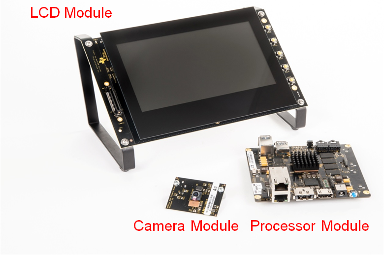
Module:
- Processor Module
- LCD Module
- Camera Module
Other components:
- µSD card with Linux SDK
- USB-to-serial debug cable
- HDMI cable for optional external display
- LCD brackets
Printed documentation:
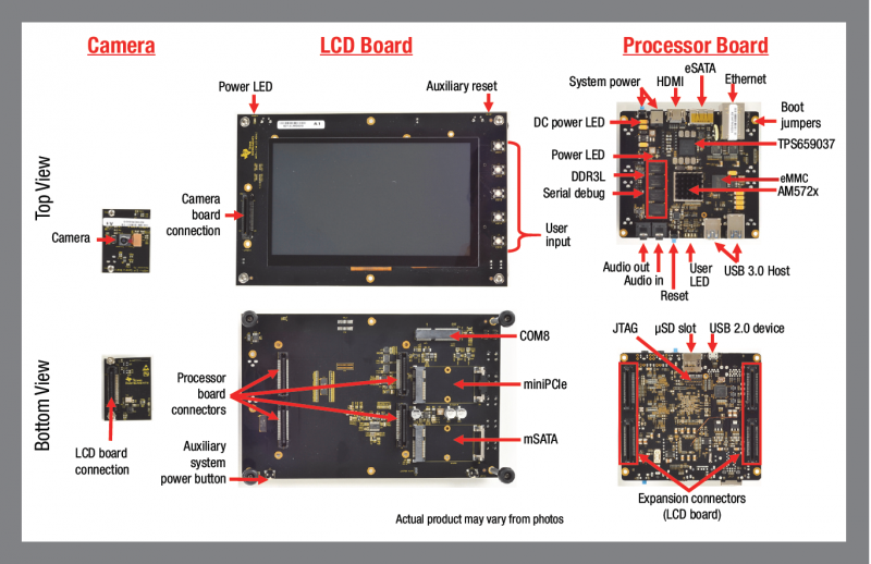
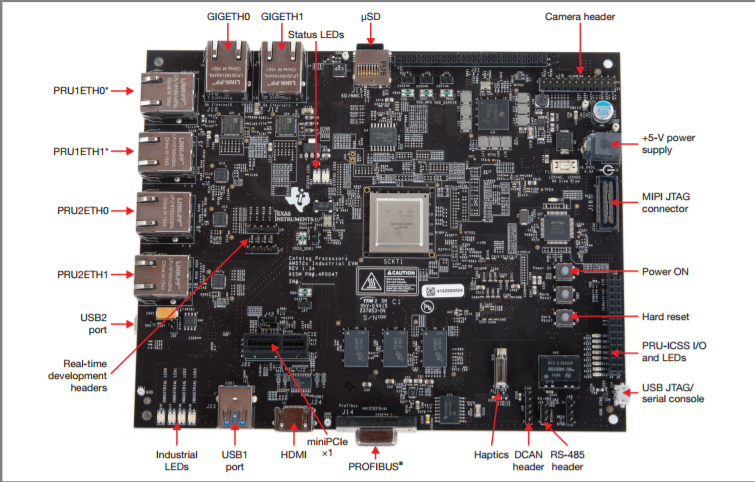
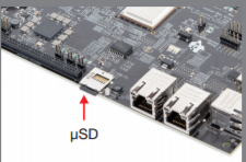
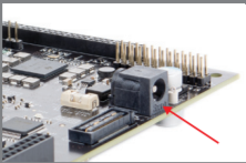
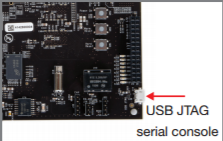
EVM Layout and Key Components
JTAG debug probes (aka Emulators) supported
List of standalone JTAG debug probes supported:
- XDS100-class JTAG debug probes (low cost, low performance). XDS100v1 is not supported.
- XDS200-class JTAG debug probes (recommended)
- XDS560v2-class JTAG debug probes (high performance)
Host Drivers
Download and install Virtual COM Port Drivers for TTL-232R-3V3 USB to UART cable from the FTDI website:
Minimal EVM setup
Setting boot switches
Other Boot Pin configurations: GP EVM Boot Options
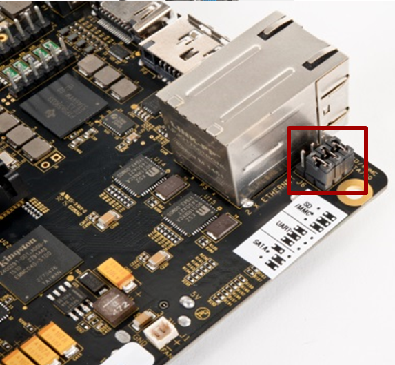
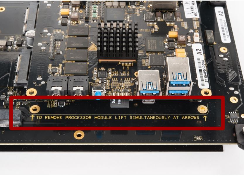
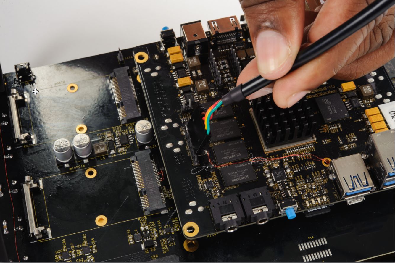
Connecting Emulator
Note: This EVM setup is only required for developers who need to connect to cores using Code Composer studio to load application.
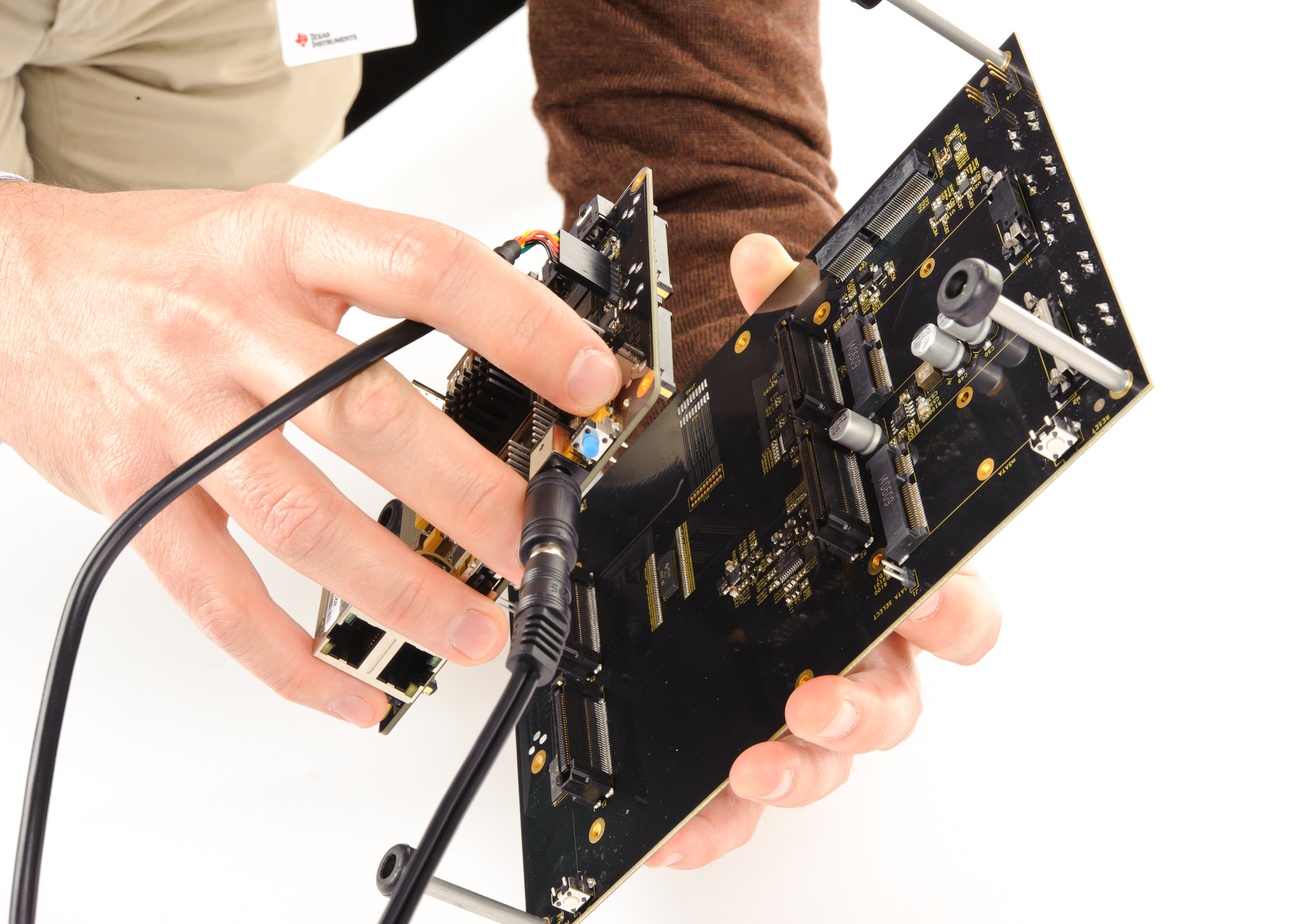
The JTAG emulation pins for the EVM are on the back of the processor module. User need to carefully unmount the processor module from the LCD panel in order to get access to the JTAG pins.
Refer to the image below for how to safely separate the processor module from the LCD panel.
|
|
Powering up the EVM
Power Supply specifications
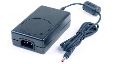
Please note that a power supply is NOT included with the AM572x Evaluation Module and needs to be purchased separately. A power supply with the following specs is needed:
- 12V DC output
- 5A output
- Positive inner and negative outer terminals
- Female barrel with 2.5mm inner diameter and 5.5mm outer diameter
- Isolated power supply
PMIC auto-off after seven seconds
The Power Management Integrated Circuit (PMIC) on the TMDSEVM572X turns off the board in seven seconds after power on to work around a hardware errata. After seven seconds, the PMIC powers off unless software writes to a PMIC register to keep it on.
In emulation setup, the GEL file will keep the PMIC on after you connect to the A15 core on the SoC. While booting from ROM bootloader user application software, would need to keep the PMIC ON while initializing the board.
In Linux boot, the uboot code keeps the PMIC On and in the TI RTOS boot scenario, the SBL component provides the same functionality
NOTE
- To allow quicker execution of the GEL before the PMIC shuts off, you can increase the JTAG TCLK Frequency in Advance settings of your target configuration to 15Mhz or to the maximum (20Mhz).
- If the above CCS connect sequence does not work in the first attempt, it means that the PMIC switched off before the GEL could initialize I2C and modify the PMIC settings. In that case, the connection has failed, hit connect in CCS debug view without removing the power cable and then immediately hit the power switch besides the power plug.
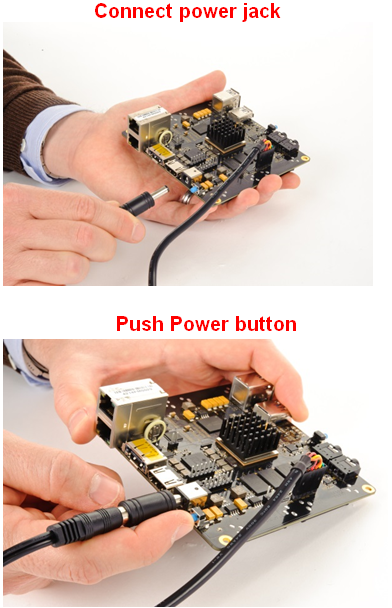
Connect Power to the EVM
CCS Setup
There are two scenarios while connecting to the EVM :
- Connect to EVM without a SD card boot image to boot the EVM
- Connect to EVM after booting an image from the SD card.
Connect without a SD card boot image
Configuring target configuration files
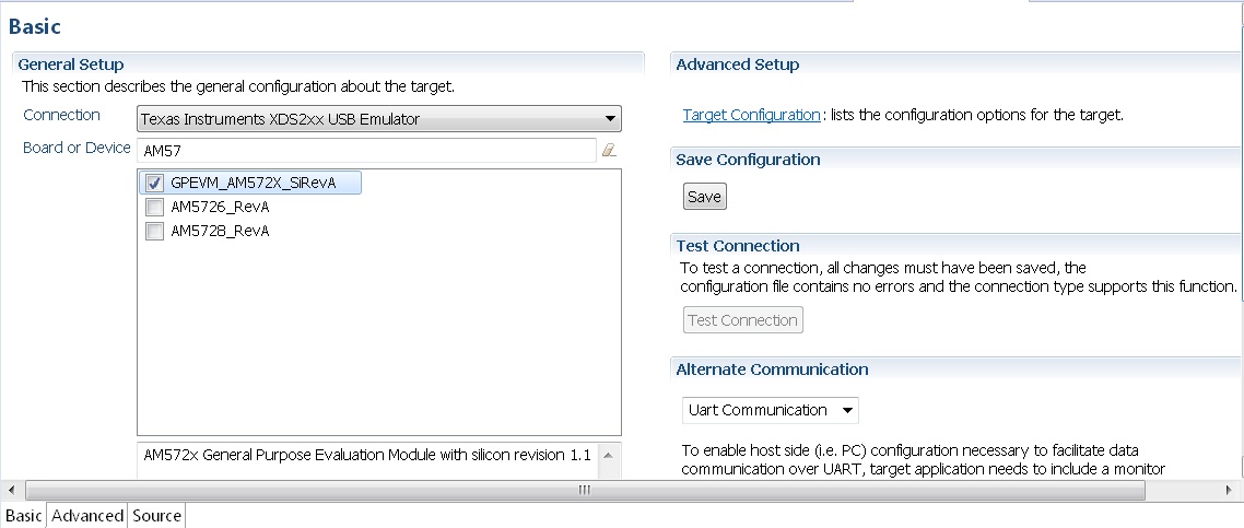
Launch CCS and create new target configuration(File->New->Target Configuration file) as shown in the images below and provide appropriate name to the configuration. Select Spectrum digital XDS200 emulator and target as GPEVM_AM572x_SiRevA.
Note: For older revisions of CCSv6, If you don`t find the GPEVM_AM572x_SiRevA target make sure you have installed the CCSv6 package with support for Sitara Processors and done the software update correctly from the Help Menu to get the latest Sitara CSP package.
In advance settings, make sure that the gel files are populated correctly. The following GEL files and their corresponding cores are provided below:
- IcePick_D: AM572x_ICEPickD_Utility.gel
- CS_DAP_DebugSS: AM572x_dap_startup.gel
- CS_DAP_PC: AM572x_CS_DAP_PC_Utility.gel
- A15_0: AM572x_cortexa15_cpu0_startup.gel
- A15_1: AM572x_cortexa15_cpu1_startup.gel
- C66x_0: AM572x_dsp_startup.gel
- C66x_1: AM572x_dsp_startup.gel
- M4_IPU_1_C0: AM572x_cortexM4_startup.gel
- M4_IPU_1_C1: AM572x_cortexM4_startup.gel
- M4_IPU_2_C0: AM572x_cortexM4_startup.gel
- M4_IPU_2_C1: AM572x_cortexM4_startup.gel
- IVAHD: AM572x_ivahd_startup.gel
Connecting to target
Step1 : Download Code composer Studio and AM572x Sitara CSP package as described in the wiki article mentioned below:
Install Code composer Studio v6 for AM572x
Step2: AM572x EVM doesn`t have any boot switches to configure for emulation mode. so configure the boot switches to SD Boot Mode. Dont Populate the uSD card when the intent is to connect and load code over emulator and not to boot the device using uSD card.
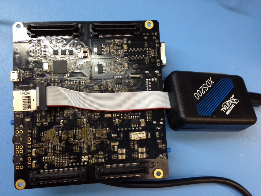
Step3: Connect an XDS200 Emulator to emulation pins at the back of the GP EVM as shown in section.Connecting_Emulator
Step4: Launch CCS and create new target configuration as discussed in the previous section.
IcePick_D: GEL Output: IVAHD ICONT1 is released from Wait-In-Reset.
IcePick_D: GEL Output: IVAHD ICONT2 is released from Wait-In-Reset.
CS_DAP_DebugSS: GEL Output: --->>> CONFIGURE DEBUG DPLL settings to 1.9 GHZs  <<<---
CS_DAP_DebugSS: GEL Output: > Setup DebugSS 1.9GHz in progress...
CS_DAP_DebugSS: GEL Output: < Done with Setup DebugSS Trace export clock (TPIU) to 97MHz
CS_DAP_DebugSS: GEL Output: < Done with Setup DebugSS PLL Clocking 1.9GHz
CS_DAP_DebugSS: GEL Output: < Done with Setup DebugSS ATB Clocking 380MHz
CS_DAP_DebugSS: GEL Output: < Done with Setup DebugSS Trace export clock (TPIU) to 97MHz
CS_DAP_DebugSS: GEL Output: --->>> TURNING ON L3_INSTR and L3_3 clocks required for debug instrumention <<<<<<----
CS_DAP_DebugSS: GEL Output: ---<<< L3 instrumentation clocks are enabled >>>> ---
CS_DAP_DebugSS: GEL Output: --->>> Mapping TIMER supsend sources to default cores <<<<<<----
CS_DAP_PC: GEL Output: Cortex-A15 1 is not in WIR mode so nothing to do.
CortexA15_0: GEL Output: --->>> AM572x GP EVM <<<---
CortexA15_0: GEL Output: --->>> AM572x Target Connect Sequence Begins ... <<<---
CortexA15_0: GEL Output: --->>> I2C Init <<<---
CortexA15_0: GEL Output: --->>> AM572x Begin MMC2 Pad Configuration <<<---
CortexA15_0: GEL Output: --->>> AM572x End MMC2 Pad Configuration <<<---
CortexA15_0: GEL Output: --->>> AM572x PG2.0 GP device <<<---
CortexA15_0: GEL Output: --->>> PRCM Clock Configuration for OPPNOM in progress... <<<---
CortexA15_0: GEL Output:    Cortex A15 DPLL OPP 0 clock config is in progress...
CortexA15_0: GEL Output:    Cortex A15 DPLL is already locked, now unlocking...
CortexA15_0: GEL Output:    Cortex A15 DPLL OPP 0 is DONE!
CortexA15_0: GEL Output:    IVA DPLL OPP 0 clock config is in progress...
CortexA15_0: GEL Output:    IVA DPLL OPP 0 is DONE!
CortexA15_0: GEL Output:    PER DPLL OPP 0 clock config in progress...
CortexA15_0: GEL Output:    PER DPLL already locked, now unlocking
CortexA15_0: GEL Output:    PER DPLL OPP 0 is DONE!
CortexA15_0: GEL Output:    CORE DPLL OPP 0 clock config is in progress...
CortexA15_0: GEL Output:    CORE DPLL OPP  already locked, now unlocking....
CortexA15_0: GEL Output:    CORE DPLL OPP 0 is DONE!
CortexA15_0: GEL Output:    ABE DPLL OPP 0 clock config in progress...
CortexA15_0: GEL Output:    ABE DPLL OPP 0 is DONE!
CortexA15_0: GEL Output:    GMAC DPLL OPP 0 clock config is in progress...
CortexA15_0: GEL Output:    GMAC DPLL OPP 0 is DONE!
CortexA15_0: GEL Output:    GPU DPLL OPP 0 clock config is in progress...
CortexA15_0: GEL Output:    GPU DPLL OPP 0 is DONE!
CortexA15_0: GEL Output:    DSP DPLL OPP 0 clock config is in progress...
CortexA15_0: GEL Output:    DSP DPLL OPP 0 is DONE!
CortexA15_0: GEL Output:    PCIE_REF DPLL OPP 0 clock config is in progress...
CortexA15_0: GEL Output:    PCIE_REF DPLL OPP 0 is DONE!
CortexA15_0: GEL Output: --->>> PRCM Clock Configuration for OPP 0 is DONE! <<<---
CortexA15_0: GEL Output: --->>> PRCM Configuration for all modules in progress... <<<---
CortexA15_0: GEL Output: --->>> PRCM Configuration for all modules is DONE! <<<---
CortexA15_0: GEL Output: --->>> DDR3 Initialization is in progress ... <<<---
CortexA15_0: GEL Output:    DDR DPLL clock config for 532MHz is in progress...
CortexA15_0: GEL Output:    DDR DPLL clock config for 532MHz is in DONE!
CortexA15_0: GEL Output:        Launch full leveling
CortexA15_0: GEL Output:        Updating slave ratios in PHY_STATUSx registers
CortexA15_0: GEL Output:        as per HW leveling output
CortexA15_0: GEL Output:        HW leveling is now disabled. Using slave ratios from
CortexA15_0: GEL Output:        PHY_STATUSx registers
CortexA15_0: GEL Output:        Two EMIFs in interleaved mode - (2GB total)
CortexA15_0: GEL Output: --->>> DDR3 Initialization is DONE! <<<---
CortexA15_0: GEL Output: --->>> AM572x Target Connect Sequence DONE !!!!!  <<<---
CortexA15_0: GEL Output: --->>> IPU1SS Initialization is in progress ... <<<---
CortexA15_0: GEL Output: --->>> IPU1SS Initialization is DONE! <<<---
CortexA15_0: GEL Output: --->>> IPU2SS Initialization is in progress ... <<<---
CortexA15_0: GEL Output: --->>> IPU2SS Initialization is DONE! <<<---
CortexA15_0: GEL Output: --->>> DSP1SS Initialization is in progress ... <<<---
CortexA15_0: GEL Output: DEBUG: Clock is active ...
CortexA15_0: GEL Output: DEBUG: Checking for data integrity in DSPSS L2RAM ...
CortexA15_0: GEL Output: DEBUG: Data integrity check in GEM L2RAM is sucessful!
CortexA15_0: GEL Output: --->>> DSP1SS Initialization is DONE! <<<---
CortexA15_0: GEL Output: >> START ==> Enable L3 Clk
CortexA15_0: GEL Output: >> Change Suspend source for GPTimer5 to DSP1
CortexA15_0: GEL Output: --->>> DSP2SS Initialization is in progress ... <<<---
CortexA15_0: GEL Output: DEBUG: Clock is active ...
CortexA15_0: GEL Output: DEBUG: Checking for data integrity in DSPSS L2RAM ...
CortexA15_0: GEL Output: DEBUG: Data integrity check in GEM L2RAM is sucessful!
CortexA15_0: GEL Output: --->>> DSP2SS Initialization is DONE! <<<---
CortexA15_0: GEL Output: --->>> IVAHD Initialization is in progress ... <<<---
CortexA15_0: GEL Output: DEBUG: Clock is active ...
CortexA15_0: GEL Output: --->>> IVAHD Initialization is DONE! ... <<<---
CortexA15_0: GEL Output: --->>> PRUSS 1 and 2 Initialization is in progress ... <<<---
CortexA15_0: GEL Output: --->>> PRUSS 1 and 2 Initialization is in complete ... <<<---
Multi-core Initialization
After connecting to the boot master core – typically the ARM core – you may need to connect to a slave core in order to run code. Depending on your SOC, the slave core can be
- DSP C66x
- ARM M4
- PRUSS
- IVAHD
Typically the slave cores will wait in reset state until the master core
wakes up the slave core to run code. To connect to the slave core on
AM57x, go to Scripts menu in CCS Debug View and under AM572x
MULTICORE Initialization enable the corresponding sub system clock.
For example, enable DSP11SSClkEnable_API for the first DSP core.
After running the clock enable option, you can connect to the core.
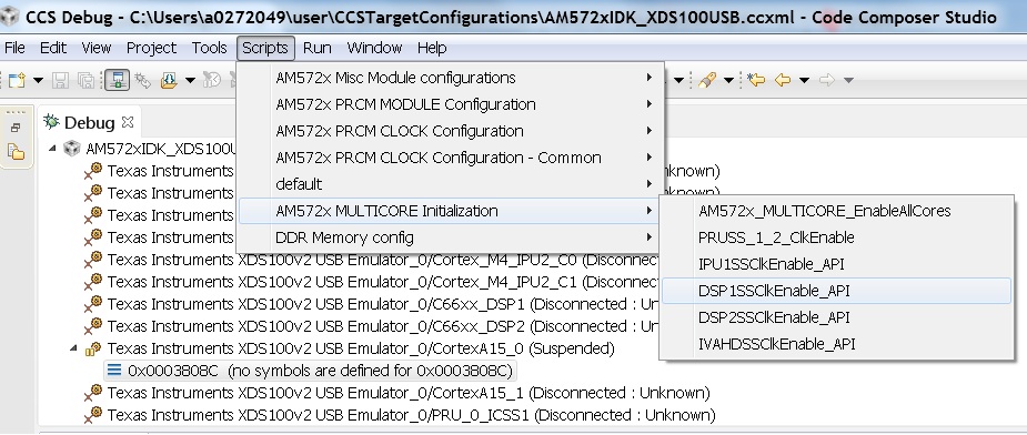
If you wish to run TI RTOS code on DSP, please also run the Timer Suspend Control Options.
Connect after booting from SD card
When you boot an image from the SD card, the secondary boot loader will configure the device clocks, DDR and wake up the slave cores on the AM572x processor on GP EVM hence you don`t need the GEL initialization scripts to redo the clock and DDR settings.
Note: If you are running the Image processing demo or have created an SD card with the SBL (mlo) for booting the board then please follow the following procedure
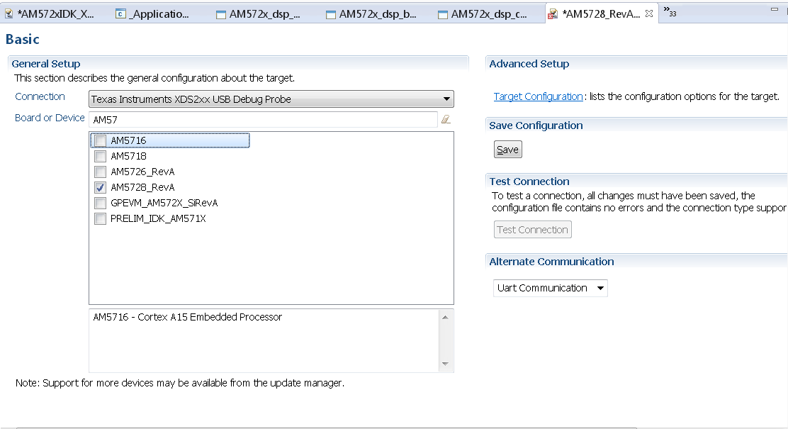
Configuring target configuration files
Launch CCS and create new target configuration(File->New->Target Configuration file) as shown in the images below and provide appropriate name to the configuration. Select Spectrum digital XDS200 emulator and target as AM5728_RevA. This target setting will not populate the GEL files when you connect to the target
Note: If you don`t find the AM572x_RevA target make sure you have installed the CCSv6.1.1 package and done the software update correctly.
GEL file options
Changing SoC Operating point
The GEL file for setting the clocks on the SoC provides 3 Operating points OPP_NOM, OPP_OD and OPP_HIGH.
OPP_NOM PLL Settings:
- ARM = 1000 MHz
- DSP = 600 Mhz
- IVA = 532 Mhz
OPP_OD PLL Settings:
- ARM = 1176 MHz
- DSP = 600 Mhz
- IVA = 430 Mhz
- GPU =500 Mhz
OPP_HIGH PLL Settings:
- ARM = 1500 MHz
- DSP = 700 Mhz
- GPU = 425 Mhz
- IVA = 388.3 Mhz
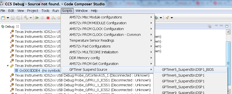
Timer Suspend Control Options for DSP
On AM57xx devices, all the timers on the chip have their suspend control signal routed to the A15 core. Which means that if any of the slave cores are using these timers, the timers will continue to run even when the slave core has been paused. The timer will only pause when the A15 core is halted.
This is confusing while debugging code on slave cores if you are relying on timer for logging, inserting delays or if the timer keeps firing interrupts even when the core is halted. One such scenario occurs with GPtimer5 when DSP developers are using SYS/BIOS. The OS uses GPtimer5 on the DSP and forces a frequency check to confirm the timer configuration, however the OS can’t gain access to the timer due to the hook up of the suspend control signals.
Due to this issue the SYS/BIOS developers will need to configure an additional CCS configuration check to connect the GPTimer suspend control signal to the DSP as shown in the image below:
Other How-To Options
Connecting the UART
Connecting FTDI cable to the 6 pin UART header for serial debug
Note: Pin 1 corresponds to ground.
Connect the USB end to the host. If you connect to the EVM UART, use the following host configuration setup in the serial terminal software (Minicom, Teraterm, etc) Baud Rate: 115200 Data Bits: 8 Parity: None Flow Control: Off
Connect Ethernet cable to enable Network Connectivity
For ethernet connectivity connect the ethernet cable to the top serial port which is port 0 on the GP EVM.
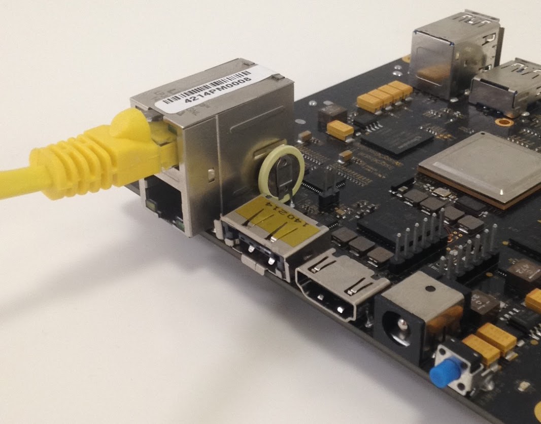
You can connect the other end of the cable directly to the host or through a network switch based on the configuration required for your test setup.
6.3.2. TMDXIDK5728 Hardware Setup
Description
The TMDXIDK5728 is a standalone test, development, and evaluation module system that enables developers to write software and develop hardware for industrial communication type applications. It has been equipped with a TI AM572x processor and a defined set of features to allow the user to experience industrial communication solutions using serial or Ethernet based interfaces. Using standard interfaces, the IDK may interface to other processors or systems and act as a communication gateway in this case. In addition it can directly operate as a standard remote I/O system or simple sensor connected to an industrial communication network. The embedded emulation logic allows emulation and debug using standard development tools such as TI’s Code Composer Studio by just using the supplied USB cable.
EVM Layout and key components
- PRU1ETH0 and PRU2ETH0 are not enabled by default
Quick Start Guide
This section talks about how to quickly setup the AM572x Industrial Development Kit (IDK) EVM. This guide is a Beta version and it is designed to help you through the initial setup of the EVM.
| 1. Once you have received the TI-RTOS or Linux™ software from your TI representative, create a bootable µSD card (using the included blank µSD) and insert it into the EVM |
|
| 2. Connect the power cable to the power jack on the board and plug in to an AC power source |
|
Note: When powering this IDK, always use the recommended power supply (GlobTek Part Number TR9CA6500LCP-N, Model Number GT-43008-3306-1.0-T3) or equivalent model having output voltage of +5VDC and output current max 6.5 Amp as well as the applicable regional product regulatory/safety certification requirements requirements such as (by example) UL, CSA, VDE, CCC, PSE, etc.
| 3. Connect the microUSB cable to USB JTAG/Console port on the EVM and connect to the USB on the host. Connect Ethernet cable to GIG ETH0 if Network connectivity is required |
|
Note: The serial port will not show up on the host PC until you power on the EVM.
| 4. Select the power ON button to run power the IDK. |
|
After, you power on the EVM the Status, Industrial LED2, Industrial LED3 will turn on. If the microUSB cable is pluged in then the LED corresponding to FTDI UARTtoUSB will be turned on.
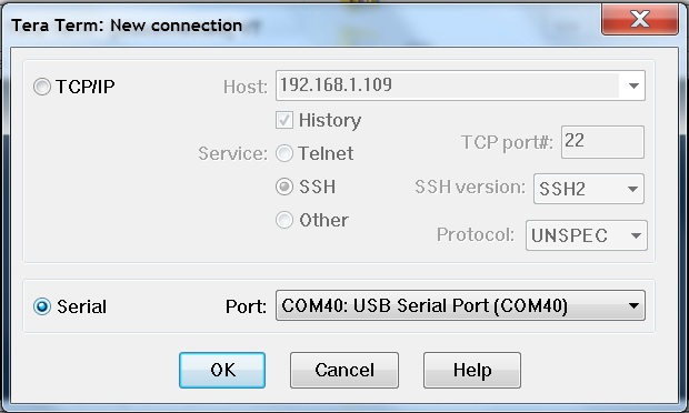
| 5. Users can now connect to UART and the on board XDS100 emulator from the host machine.For UART port connections set the serial terminal software Tera term/minicom/hyperterminal to baudrate 115200 to see log messages. Connecting to target using emulator has been discussed in the section below. | |
|

|
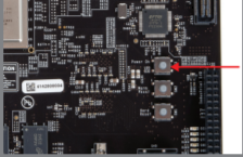
Connecting IDK EVM to Code Composer Studio
Step1 : Download Code composer Studio and AM572x Sitara CSP package as described in the wiki article mentioned below:
Install Code composer Studio for AM572x
Step2: Connect IDK EVM as described in the Quick Start Guide. Populating the uSD card is not required as the intent is to connect and load code over emulator and not to boot the device using uSD card. AM572x IDK doesn`t have any boot switches to configure for emulation mode.
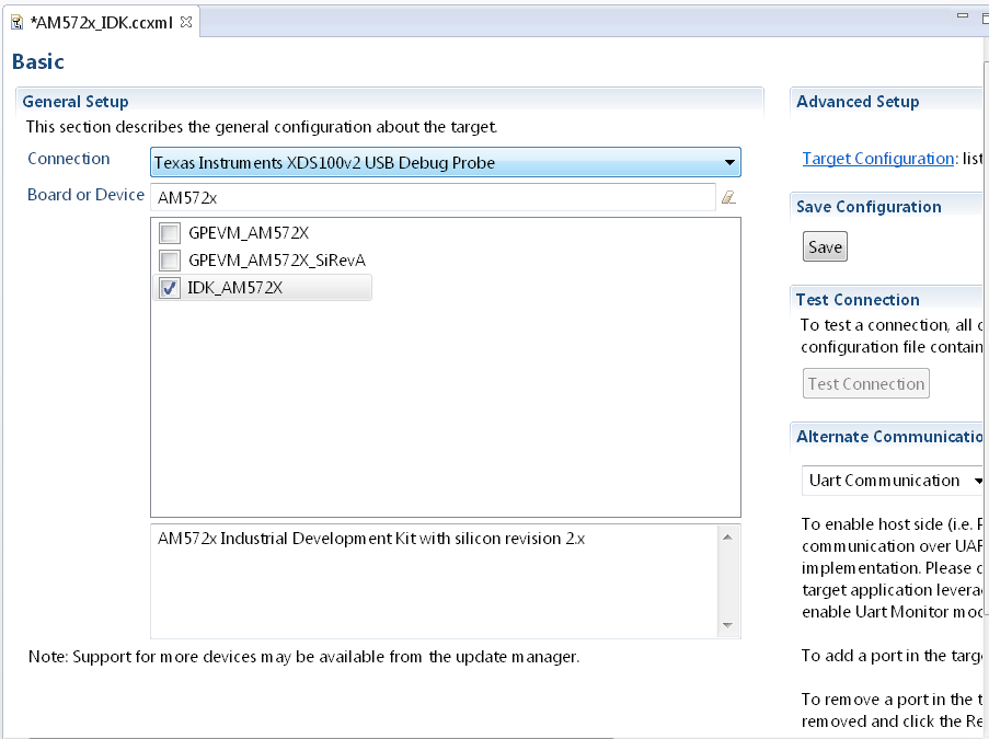
Step3: Launch CCS and create new target configuration(File->New->Target Configuration file) as shown in the images below and provide appropriate name to the configuration. Select Texas Instuments XDS100v2 emulator and target as IDK_AM572x.
NOTE If you don`t find the IDK_AM572x target make sure you have installed the Sitara Device support version 1.3.x package correctly
- Cortex_A15_0: ..\..\emulation\boards\am572x\gel\idk_am572x.gel
- C66x_DSP1: ..\..\emulation\boards\am572x\gel\AM572x_dsp_startup.gel
- Cortex_M4_IPU1_C0: ..\..\emulation\boards\am572x\gel\AM572x_cortexM4_startup.gel
Note: GEL files are located under ccsv6\ccs_base\emulation\boards\am572x\gel after the CSP package is installed
CortexA15_0: GEL Output: --->>> AM572x Target Connect Sequence Begins ... <<<---
CortexA15_0: GEL Output: --->>> AM572x Begin MMC2 Pad Configuration <<<---
CortexA15_0: GEL Output: --->>> AM572x End MMC2 Pad Configuration <<<---
CortexA15_0: GEL Output: --->>> AM572x PG1.1 GP device <<<---
CortexA15_0: GEL Output: --->>> I2C Init <<<---
CortexA15_0: GEL Output: --->>> PRCM Clock Configuration for OPPNOM in progress... <<<---
CortexA15_0: GEL Output:    Cortex A15 DPLL OPP 0 clock config is in progress...
CortexA15_0: GEL Output:    Cortex A15 DPLL is already locked, now unlocking...
CortexA15_0: GEL Output:    Cortex A15 DPLL OPP 0 is DONE!
CortexA15_0: GEL Output:    IVA DPLL OPP 0 clock config is in progress...
CortexA15_0: GEL Output:    IVA DPLL OPP 0 is DONE!
CortexA15_0: GEL Output:    PER DPLL OPP 0 clock config in progress...
CortexA15_0: GEL Output:    PER DPLL already locked, now unlocking
CortexA15_0: GEL Output:    PER DPLL OPP 0 is DONE!
CortexA15_0: GEL Output:    CORE DPLL OPP 0 clock config is in progress...
CortexA15_0: GEL Output:    CORE DPLL OPP  already locked, now unlocking....
CortexA15_0: GEL Output:    CORE DPLL OPP 0 is DONE!
CortexA15_0: GEL Output:    ABE DPLL OPP 0 clock config in progress...
CortexA15_0: GEL Output:    ABE DPLL OPP 0 is DONE!
CortexA15_0: GEL Output:    GMAC DPLL OPP 0 clock config is in progress...
CortexA15_0: GEL Output:    GMAC DPLL OPP 0 is DONE!
CortexA15_0: GEL Output:    GPU DPLL OPP 0 clock config is in progress...
CortexA15_0: GEL Output:    GPU DPLL OPP 0 is DONE!
CortexA15_0: GEL Output:    DSP DPLL OPP 0 clock config is in progress...
CortexA15_0: GEL Output:    DSP DPLL OPP 0 is DONE!
CortexA15_0: GEL Output:    PCIE_REF DPLL OPP 0 clock config is in progress...
CortexA15_0: GEL Output:    PCIE_REF DPLL OPP 0 is DONE!
CortexA15_0: GEL Output: --->>> PRCM Clock Configuration for OPP 0 is DONE! <<<---
CortexA15_0: GEL Output: --->>> PRCM Configuration for all modules in progress... <<<---
CortexA15_0: GEL Output: --->>> PRCM Configuration for all modules is DONE! <<<---
CortexA15_0: GEL Output: --->>> DDR3 Initialization is in progress ... <<<---
CortexA15_0: GEL Output:    DDR DPLL clock config for 532MHz is in progress...
CortexA15_0: GEL Output:    DDR DPLL clock config for 532MHz is in DONE!
CortexA15_0: GEL Output: DEBUG: Overall DDR configuration
CortexA15_0: GEL Output: DEBUG: EMIF1 and EMIF1 DDR IOs config (CTRL_MODULE_CORE_PAD module)
CortexA15_0: GEL Output: DEBUG: DDR PHY config (CTRL_MODULE_WKUP module)
CortexA15_0: GEL Output: DEBUG: EMIF1 ctrl + associated DDR PHYs initial config (EMIF1 module)
CortexA15_0: GEL Output: DEBUG: EMIF1 channel - Launch full levelling
CortexA15_0: GEL Output: DEBUG: EMIF2 ctrl + associated DDR PHYs initial config (EMIF2 module)
CortexA15_0: GEL Output: DEBUG: EMIF1 channel - Launch full levelling
CortexA15_0: GEL Output: DEBUG: Setting LISA maps in non-interleaved dual-EMIF mode
CortexA15_0: GEL Output: --->>> DDR3 Initialization is DONE! <<<---
CortexA15_0: GEL Output: --->>> AM572x Target Connect Sequence DONE !!!!!  <<<
Step6 : To connect to the DSP, M4,PRUSS or to IVAHD go to Scripts menu and under AM572x MULTICORE Initialization enable the corresponding Sub system clock Enable API.For Eg. FOr DSP1 select DSP11SSClkEnable_API. After running the clock enable option, you can connect to the core.
6.3.3. 66AK2G02 GP EVM Hardware Setup
Description
The EVMK2G is a high performance, cost-efficient, standalone development platform that enables users to evaluate and develop applications for the Texas Instrument’s Keystone2 System-on-Chip (SoC) 66AK2G02. The Key features of EVM are:
Processor and controller
- K2G SoC 66AK2G02 is based on keystone II architecture with ARM cortex A15 @600MHz and C66x DSP @600MHz
- Board Management Controller (BMC) for board management functions like system status and Boot mode control
Volatile and non volatile Memory/Interfaces:
- 2GByte of DDR3L with ECC
- 2Gbit of NAND Flash
- 128Mbit of SPI Flash
- 512Mbit of QSPI Flash
- 128kByte of I2C EEPROM for Boot support from I2C
- Micro SD-Card slot
- 16GByte of eMMC
High speed and Serial Interfaces
- Gigabit Ethernet port supporting 10/100/1000 Mbps data rate on RJ45 connector
- PCIe x1 card slot
- COM8 interface
- DCAN and MLB interfaces
- One USB2.0 host and one USB2.0 Dual-role ports
- One RS232 serial interface on DB9 connector or UART over mini-USB connector, One UART interface on 6 pin header
Multimedia and display:
- 4.3” LCD display with Capacitive touch (Sold separately)
- HDMI transmitter
- Audio Line In and Line Out
JTAG and Emulation:
- MIPI 60-Pin JTAG header to support all types of external emulator
- On Board XDS200 Emulator
- Powered by DC power-wall adaptor (12V/5A)
EVM Layout and Key Components
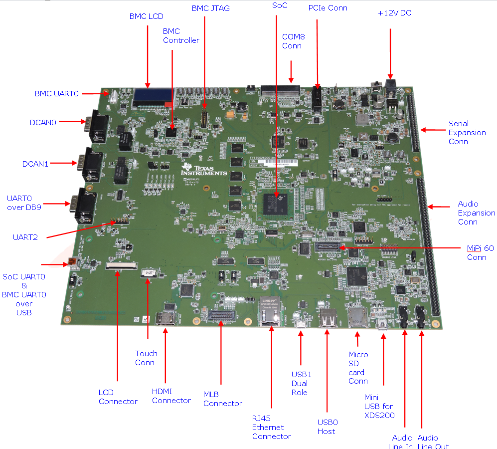
JTAG debug probes (aka Emulators) supported
List of standalone JTAG debug probes supported:
- XDS100-class JTAG debug probes (low cost, low performance). XDS100v1 is not supported.
- XDS200-class JTAG debug probes (recommended)
- XDS560v2-class JTAG debug probes (high performance)
Minimal EVM setup
Setting boot switches
The DIP Switch /Boot mode switch (SW3) is used for selecting the boot mode.
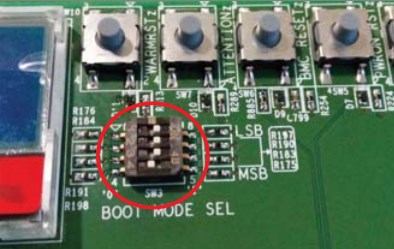
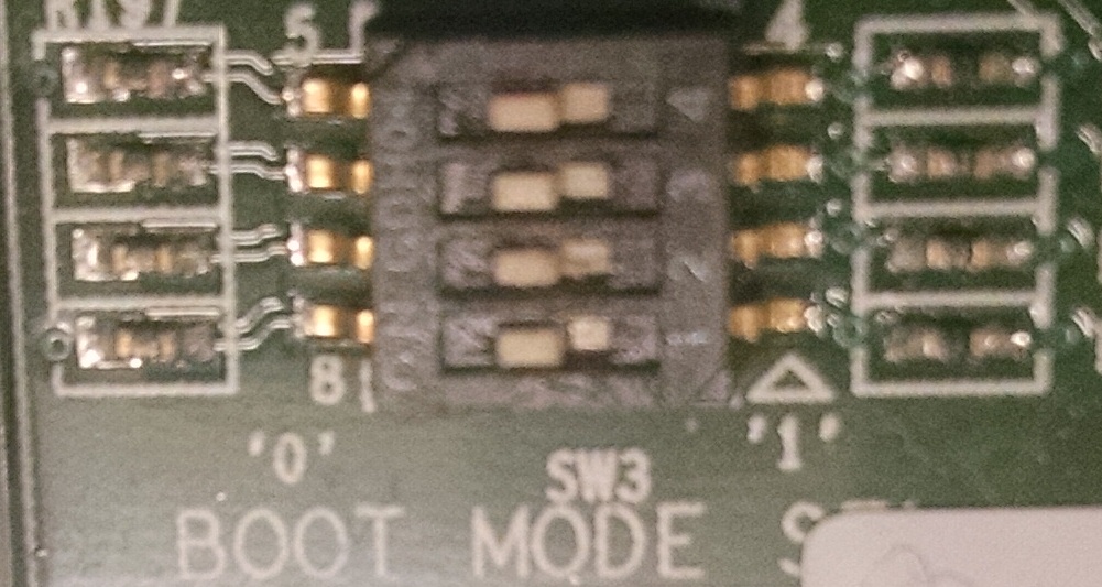
Note: Read the PCB marking around the boot switch for your EVM to interpret of ON and OFF marking on the switch
- For Rev C K2G02 GP EVM: ON = ‘0’ and OFF = ‘1’
- For Rev C/Rev D K2G12 GP EVM: ON = ‘1’ and OFF = ‘0’
Other Boot Pin configurations:
| SW3[4:1] | BOOT MODE |
|---|---|
| 0000 (0x0) | Sleep/No Boot |
| 0001 (0x1) | PCIe boot |
| 0010 (0x2) | Ethernet Boot |
| 0011 (0x3) | I2C PLL Boot |
| 0100 (0x4) | SPI No PLL Boot |
| 0101 (0x5) | SPI PLL-1 Boot |
| 0110 (0x6) | USB Boot |
| 0111 (0x7) | MMC/SD Boot |
| 1000 (0x8) | UART Boot |
| 1001 (0x9) | QSPI 96 Boot |
| 1010 (0xa) | eMMC Boot |
| 1011 (0xb) | NAND Boot |
| 1100 (0xc) | I2C No PLL Boot |
| 1101 (0xd) | SPI PLL-2 Boot |
| 1110 (0xe) | SPI PLL-3 Boot |
| 1111 (0xf) | QSPI 48 Boot |
Connecting Emulator
Note: This EVM setup is only required for developers who need to connect to cores using Code Composer studio to load application.
When external emulator is not connected to MIPI 60-pin connector, On-board XDS200 embedded JTAG emulator is the default type of emulation (SoC JTAG signals are routed to XDS200 on-board emulator). When external emulator is connected to MIPI 60-pin header, it is automatically detected and SoC JTAG signals are routed to external emulator.
On Board XDS200 emulator
EVMK2G has on-board XDS200 embedded JTAG emulation circuitry. Hence user does not require any external emulator to connect EVM with Code Composer Studio (CCS). User can connect target SoC in EVM to CCS through USB cable supplied in the EVM kit.
Use the USB to USB mini-B cable provided. Connect the USB mini-B connector to the USB mini-B interface near to the audio line in on the EVM, and the USB connector to your PC. This enables XDS-2xx emulation and is directly useable by CCS.
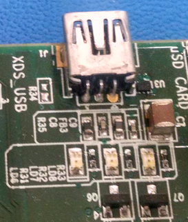
NOTE On Rev C boards and earlier revisions of the board, users who plan to connect the USB cable to USB 3.0 cable need to follow the instructions to update Emulation firmware using steps described in wiki article Updating_the_XDS200_firmware Without the firmware update, users are recommended to disconnect the mini USB cable from the XDS USB connector before powering up the EVM and reconnect after board power up is complete.
If you are using a different JTAG, you can connect it at MIPI60 connector (EMU1). The MIPI 60-pin JTAG header is provided on-board for high speed real-time emulation. All JTAG and EMUxx signals are terminated on MIPI 60-pin header.
No emulation firmware upgrade is required if users plan to use an external emulator The MIPI 60-pin JTAG header supports all standard (XDS510 or XDS560) TI DSP emulators. Please refer to the documentation supplied with your emulator for connection assistance.
Powering up the EVM
Power Supply specifications
The EVMK2G can be powered from a single +12V / 5.0A DC (60W) external power supply connected to the DC power jack (J3). Internally, +12V input is converted into required voltage levels using local DC-DC converters
Please note that a power supply is included with the 66AK2G02 Evaluation Module. The power supply has the following specs :
- 12V DC output
- 5A output
- Positive inner and negative outer terminals
- Female barrel with 2.5mm inner diameter and 5.5mm outer diameter
- Isolated power supply
CCS Setup
This section describes the setup to connect to 66AK2G02 GP EVM using Code composer Studio environment and an emulator.
There are two scenarios while connecting to the EVM :
- Connect to EVM without a SD card boot image to boot the EVM
- Connect to EVM after booting an image from the SD card.
Before discussing both these scenarios, let us look at how to pull in the latest KeystoneII device support in CCSv6
Update CCS v6 to install Keystone II device Support package
All revisions of the board require this step to be performed in order to get the latest GEL files and the target content for the K2G. This step will not be required for CCS versions higher than version 6.1.3. CCSv6.1.3 package contain KeystoneII device support package v1.1.4 which doesn`t contain 66AK2G02 GPEVM specific target files hence we recommend this update.
Step 1 All CCS v6.1.3 and earlier version users are required to update the Keystone Device Support package by going into the Help->Check For Updates
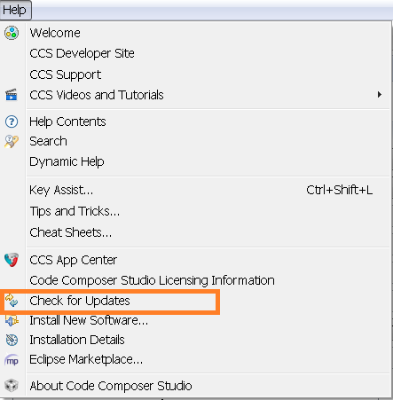
Step 2 Select Keystone2 device support package. Follow menu options to continue with the update
Step 3 After the update is complete go to Help->Installation details and check that Keystone2 device support package v1.1.5 or later are installed as shown below
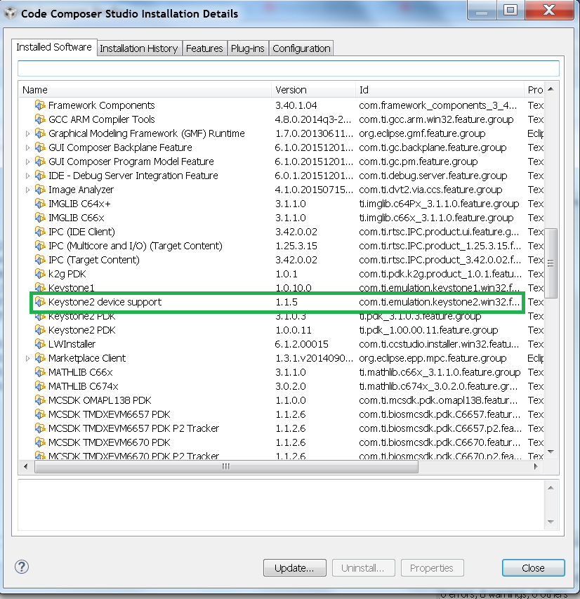
Note: The package can be downloaded separately from the link below and manually unzipped into CCSv6 installation.
Connect without a SD card boot image
Configuring target configuration files
Launch CCS and create new target configuration(File->New->Target Configuration file) as shown in the images below
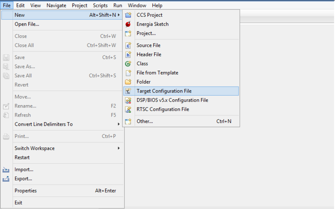
Note: If you don`t find the 66AK2G02 target make sure you have installed the CCSv6.1.3 package or for CCSv6.1.2 and earlier ensure that you have done the software update correctly as shown in the how to section below.
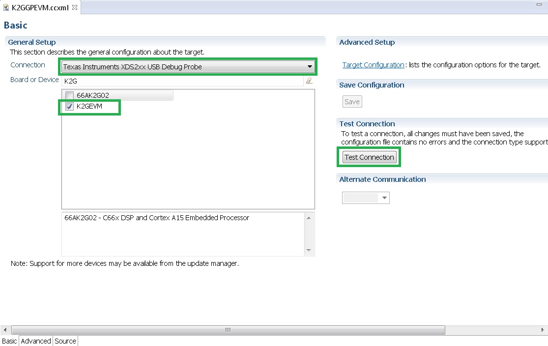
In advance settings, make sure that the gel files are populated correctly. The following GEL files and their corresponding cores are provided below:
- C66X Core: evmk2g.gel
- A15 Core: evmk2g_arm.gel
Connecting to target
Step1 : Download Code composer Studio v6.1.3 or for CCSv6.1.2 and earlier, ensure it contains Keystone device support package version 1.1.5 as described in the how to guide
Install Code composer Studio v6 for K2G
Step3: Connect an XDS200 Emulator to XDS USB of the GP EVM as shown in section.Connecting_Emulator
Step4: Launch CCS and create new target configuration as discussed in the previous section.
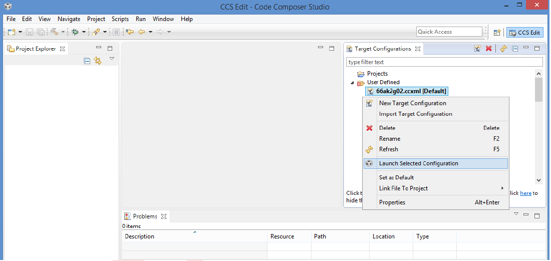
GEL Log
A15_0: GEL Output: PLL has been configured (24.0 MHz * 100 / 1 / 4 = 600.0 MHz)
A15_0: GEL Output: ARM PLL has been configured with ref clock 24MHz, -sysclkp_period 41.6666 (24.0 MHz * 100 / 1 / 4 = 600.0 MHz)
A15_0: GEL Output: Power on all PSC modules and DSP domains...
A15_0: GEL Output: Power on PCIE PSC modules and DSP domains... Done.
A15_0: GEL Output: UART PLL has been configured (24.0 MHz * 128 / 1 / 8 = 384.0 MHz)
A15_0: GEL Output: NSS PLL has been configured (24.0 MHz * 250 / 3 / 2 = 1000.0 MHz)
A15_0: GEL Output: ICSS PLL has been configured (24.0 MHz * 250 / 3 / 10 = 200.0 MHz)
A15_0: GEL Output: DSS PLL has been configured (24.0 MHz * 198 / 12 / 16 = 24.75 MHz)
A15_0: GEL Output: DDR PLL has been configured (24.0 MHz * 250 / 3 / 10 = 200.0 MHz)
A15_0: GEL Output: XMC setup complete. A15_0: GEL Output: DDR3 PLL Setup ...
A15_0: GEL Output: DDR3 PLL Setup complete, DDR3A clock now running at 400MHz.
A15_0: GEL Output: DDR3A initialization complete
Connect with a SD card boot image
Launch CCS and create new target configuration(File->New->Target Configuration file) as shown in the images below
Note: If you don`t find the 66AK2G02 target make sure you have installed the CCSv6.1.3 package or for CCSv6.1.2 and earlier ensure that you have done the software update correctly as shown in the how to section below.
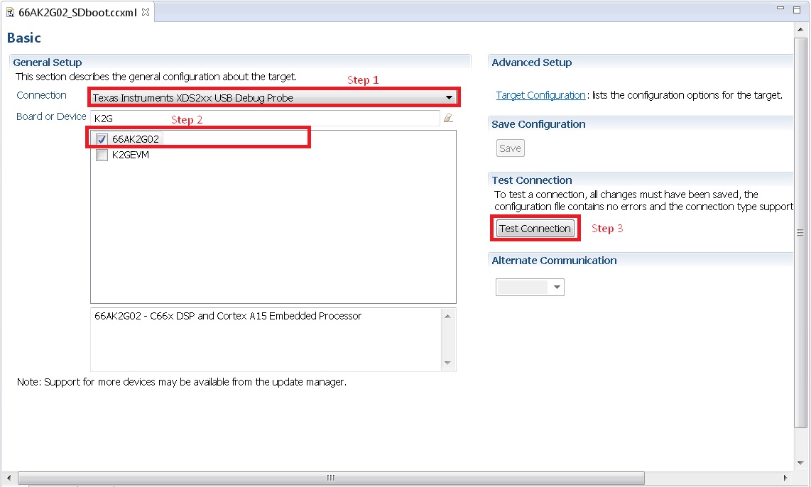
In advance settings, make sure that the no gel files are populated.
Step3: Connect an XDS200 Emulator to XDS USB of the GP EVM as shown in section.Connecting_Emulator
Step4: Launch CCS and create new target configuration as discussed in the previous section.
Step7 SD card boot image will typically load a secondary bootloader like u-boot that will put the DSP in reset so user will need to follow the instructions on wiki that talks about Taking DSP out of reset
Note: RTOS users don`t need to follow this step as the Secondary bootloader (SBL) will put the DSP in idle state and not in reset if there is no code running on the DSP.
How to guide
This section guides users who are using older versions of the GP EVM which may require an update to the firmware flashed on the EVM or hardware updates to workaround specific issues. Each section specifies the affected versions and the fix for the issue.
Create SD card to boot Linux on the GP EVM
All pre-production boards (Rev C and earlier) will not contain a SD card image in the kit without an image flashed on it for the Out of Box experience described in the Quick start guide. User are required to download the image seperately from the Processor SDK Linux portal and run a script to create the SD boot image. The steps to create the image are provided below:
Step 1 Download the image k2g-evm-linux-xx.xx.xx.xx.img.zip from the link Latest Processor SDK Linux
Step 2 Follow instructions to create a SD card for the EVM using the instruction in the SD card creation wiki
Update the BMC firmware on the EVM
The section describes how the Board Management controller firmware on the board can be updated through the BMC UART interface. All boards prior to RevC, require a BMC update for the following issue:
- CDCM chip on the board generates clocks to modules like PCIe and USB. It is possible to use PCIe only in external clock mode on the EVM. However there can be use-cases where PCIe clock should be enabled with SoC running in internal clock mode.
Step 3 Connect the mini USB cable between host PC and ‘USB to SoC UART0’ port (J23) on EVM
Step 4 Remove the jumper J10 and power on the K2G EVM
Step 5 Open the LM Flash programmer utility on the windows host machine.
Step 6 In the LM Flash Programmer Utility ‘Configuration’ tab, in the interface section, select ‘Serial (UART)’ from the drop-down box on the left.Refer to the image provided below:
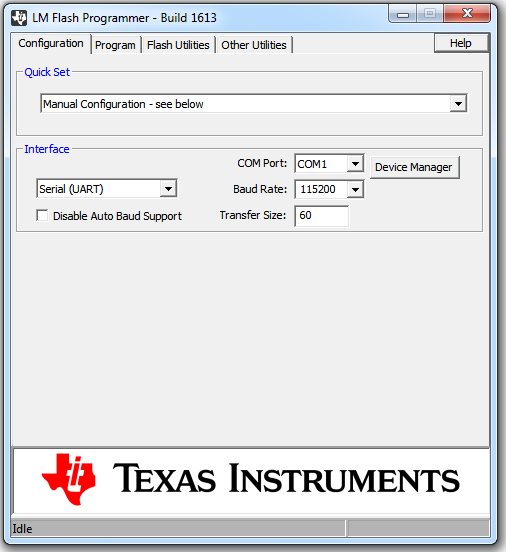
Step 7 Select the BMC COM Port and set the ‘Baud Rate’ to 115200.
- There will be two COM ports that appears on EVMs ‘USB to SoC UART0’ port. Select the one which is connected to BMC. To find which port corresponds to the BMC, you can open a serial terminal program or Device Manager on your PC and check the port number corresponding to “Silicon Labs CP210x: USB to UART Bridge: Standard COM Port (COM##)” as shown below:
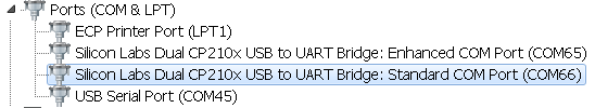
Note: BMC outputs boot logs to serial console when EVM is powered ON. Connect the ‘USB to SoC UART0’ port to standard serial console application to find the right COM port that is connected to BMC.
Step 8 Set ‘Transfer Size’ to 60, and make sure ‘Disable Auto Baud Support’ is unchecked.
Step 9 In the ‘Program’ tab, select the binary image file bmc_evmKS2_K2G.bin in the section ‘Select.bin file’.
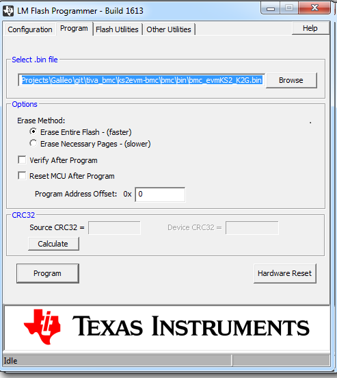
Step 10 Leave all other options as default, and press the ‘Program’ button.
Step 11 Wait till ‘Program Complete’ status in the status bar.
Step 12 Connect the jumper J10 and reboot the EVM
Update XDS200 firmware and hardware components on the GP EVM
Note: This update is only required if you are using the on board XDS200 debug probe.
The RevB and RevC boards are using an earlier version of the XDS200 firmware. We have observed the following issues when hooking up the internal XDS200 USB debug probe to a host machine.
- XDS200 Emulator USB cable need to be re-plugged every time board is power cycled/reset to avoid leakage on power supply VCC1V8_XDS which can damage the regulator or other ICs
Workaround for this issue
- Use external emulators with the MIPI 60 adapter included int he kit.
- Perform following firmware and hardware updates to the GP EVM (RevC and earlier)
Software Update Required
Steps to update the XDS200 firmware on the EVM are archived on the wiki article Updating_the_XDS200_firmware
Hardware updates required
- Replace R431 & R442 to 200E
- Mount resistors R95, R107, R108, R115.
- Mount D2, R600, R599 components.
- Remove FB3 and connect a wire from R64.2 ‘rVCC_VBUS_XDS’ and R67.2 ‘VCC5V0_DCDC’ as shown in the image below:
Update the EVM for improved USB performance
The external resistors for the USB (R442 and R431) are currently 10k Ω. We recommend that users need to replace these with 200 Ω / 1%.
Useful Resources and Support
6.4. Linux Porting Guide for AM571x/AM570x Speed Grades
Overview
The AM57x Family of Processors includes a wide range of operating performance to meet the needs of a number of broad applications. Among these options are a variety of speed grades to meet different performance points. These devices have a number of specialized cores to provide applications specific computation capabilities. These cores can be run at different speeds to fine tune the processor to the needs of the application, power budget, thermal characteristics, etc.
The Processor SDK for Linux is a software development package provided to speed development by providing a software reference. This package now includes support for then entire AM57x family of processors which can be broken down into the AM572x, AM571x, and AM570x sets of devices or sub-familes. Most of the devices in this family are supported by the Processor SDK for Linux right out of the box. This support is tested and validated on TI designed EVMs. These EVMs use the highest performance devices in the family in order to allow users to evaluate the entire spectrum of performance.
In order to move the Processor Linux SDK from a TI EVM to another customized board, a “board port” of Linux must occur to adapt the software to any of the changes between the TI EVMs and the custom board. Since Linux requires a bootloader, that must be “board ported” as well. The Processor Linux SDK used U-Boot as the bootloader. So, U-Boot and Linux need to be adapted to the custom board to account for any differences between it and the EVMs that TI provides. One of these differences might be a different speed grade of the processor. In that case, changes may be necessary as part of the board port to allow for this new speed grade. This document highlights the changes that need to be considered in this board port effort to other speed grades of the AM57xx family of devices.
For example, the AM571x Industrial Development Kit is designed with the AM5718xXx device. This device, which has an “X” speed grade, is rated at 1 GHz operation for the ARM Cortex-A15 core with the ability to go to 1.5 GHz under certain conditions (Please see the AM5718 Data Sheet, section 9.1 Device Nomenclature, for more information). The Processor SDK for Linux includes code in U-Boot and Linux Kernel to set the processor up with this configuration. If a custom board wanted to use a different speed or configuration, the software would need to be changed accordingly as part of the board port.
The AM571x and AM570x series include “D” speed grade parts that are characterized at 500 MHz operation for the ARM Cortex-A15 core. The AM570x series also includes a “J” speed grade that is different than the “X” speed grades for the AM572/1x. If one of these devices is being used on the custom board, U-Boot and Linux need to be changed to account for this difference. If this change is not made, the device could be running out of specification. These changes may reach across other cores and clocks on the device as well, depending on what speeds they need to operate at. This document is not an exhuastive list of all the changes needed for a proper board port as it focused on the changes needed to enable different speed grades.
U-Boot Changes to Consider
U-Boot is the bootloader used with the Processor SDK for Linux. Much of the clock configuration is done one time within U-Boot to configure the processor for correct operation.
Add 500 MHz for MPU Operation
When using “D” rated parts that run at 500 MHz, a clock table entry for this speed needs to be added to the U-Boot sources in arch/arm/cpu/armv7/omap5/hw_data.c.
static const struct dpll_params mpu_dpll_params_500mhz[NUM_SYS_CLKS] = {
        {-1, -1, -1, -1, -1, -1, -1, -1, -1, -1, -1, -1},       /* 12 MHz   */
        {200, 7, -1, -1, -1, -1, -1, -1, -1, -1, -1, -1},       /* 20 MHz   */
        {-1, -1, -1, -1, -1, -1, -1, -1, -1, -1, -1, -1},       /* 16.8 MHz */
        {365, 13, -1, -1, -1, -1, -1, -1, -1, -1, -1, -1},      /* 19.2 MHz */
        {-1, -1, -1, -1, -1, -1, -1, -1, -1, -1, -1, -1},       /* 26 MHz   */
        {500, 26, -1, -1, -1, -1, -1, -1, -1, -1, -1, -1},      /* 27 MHz   */
        {-1, -1, -1, -1, -1, -1, -1, -1, -1, -1, -1, -1},       /* 38.4 MHz */
};
Change Structures to Use New Clock Table Entry
In order to use this new entry for the MPU, the dplls structure that is being used needs to be modified. The file that configures this for the IDK is board/ti/am57xx/board.c. This particular file is where most of the changes for a board port of U-Boot to a new board should exist. As shipped, this file uses the dra7xx_dplls structure back in hw_data.c. This structure should be modified to use the 500 MHz dpll_params structure added above.
To boot at 500MHz, modify the the dplls structure to use 500MHz instead of 1GHz:
.mpu = mpu_dpll_params_500mhz,
This structure is also used to set several other clocks. Take time to make sure that these settings also comply with the part that is being used on the custom board.
Configure DDR Interfaces
An important one to consider is the speed of the DDR memory. The clock for the DDR is selected using the same dplls structure. Some higher speed grade parts support a 667 MHz DDR clock, but some of the lower speed grade parts only support a 533 MHz DDR3 clock. Make sure to choose the appropriate DDR clock for the device on the custom board.
Over in the board/ti/am57xx/board.c file, make sure that the EMIF is being configured correctly for the appropriate speed, and that the appropriate number of EMIFs is being selected to match the part being used. The Processor SDK for Linux includes board detection logic along with a defined EEPROM structure included on TI boards to make executing the same U-Boot executable on multiple TI boards possible. For example, one U-Boot binary will execute correctly on an AM572x GP-EVM, AM572x IDK, and AM571x IDK even though an AM572x part has 2 DDR interfaces running at 533 MHz and the AM571x (and AM570x) only have one running at 667 MHz. This code can be kept or removed by the board port. As changes are made, the code must make sure to configure the new board correctly, with the appropriate number of DDR interfaces and speed configuration.
For AM571x and AM570x, make sure to use the code for the AM571x IDK in board/ti/am57xx/board.c to select 1 EMIF:
.dmm_lisa_map_3 = 0x80640100,
Set Speeds for Other Processing Cores
There are a number of cores on these devices and each has a configurable clock. This clock configuration is done in arch/arm/cpu/armv7/omap5/fdt.c. In that file, there are voltage domain configurations for the DSP, IVA, and GPU cores. Here’s an example of the DSP’s:
u32 dra7_opp_dsp_clk_rates[NUM_OPPS][OPP_DSP_CLK_NUM] = {
    {}, /*OPP_LOW */
    {600000000, 600000000, 400000000}, /* OPP_NOM */
    {700000000, 700000000, 466666667}, /* OPP_OD */
    {750000000, 750000000, 500000000}, /* OPP_HIGH */
};
Here there are settings for 3 different performance points (NOM, OD, and HIGH), usually coordinated with the higher speed grade parts. In the case of the “D” speed grade parts, which specify the DSP is supposed to run at 500 MHz and there is not a correctly defined entry. This structure should be modified to either use the OPP_LOW entry, or simply modifiy one of the other entries (ex. OPP_NOM) with the correct entry for 500 MHz operation.
The OPP is chosen via U-Boot build configuration by defining the OPP that U-Boot should use. The configuration file for building U-Boot for the AM57x boards should serve as a great reference. It is located in configs/am57xx_evm_defconfig. A quick review of this file will reveal that the Processor SDK sets these values to OPP_HIGH by default. A board using a different processor that does not support this speed should change this to a more appropriate value for each core by setting the appropriate configuration (CONFIG_DRA7_GPU_OPP_LOW=y, for example).
Linux Changes to Consider
In this case, the Linux board port is managed by the Device Tree Source, or dts file. The dts files provided with the SDK that are used for the EVM use a variety of include (or, dtsi) files that overlay on top of each other to form the complete dts. For example, the am571x-idk.dts includes the dra7.dtsi file. The dra7.dtsi file defines nodes like these to specify the OPPs that will be used by Linux:
cpu0_opp_table: opp_table0 {
        compatible = "operating-points-v2";
        opp-shared;

        opp_nom@1000000000 {
            opp-hz = /bits/ 64 <1000000000>;
            opp-microvolt = <1060000 850000 1150000>;
            opp-supported-hw = <0xFF 0x01>;
            opp-suspend;
        };

        opp_od@1176000000 {
            opp-hz = /bits/ 64 <1176000000>;
            opp-microvolt = <1160000 885000 1160000>;
            opp-supported-hw = <0xFF 0x02>;
        };

        opp_high@1500000000 {
            opp-hz = /bits/ 64 <1500000000>;
            opp-microvolt = <1210000 950000 1250000>;
            opp-supported-hw = <0xFF 0x04>;
        };
};
These are the appropriate settings for the speed grade of device found on the EVMs. Since they are not correct for a “D” or “J” speed grade parts, the correct value can easily be overlaid using the new board’s dts file. The build procedure for a device tree file will use the last value that touches a node. Here’s an example of changing OPP_NOM to 500 MHz by adding this entry to the boards dts file (ex. am57xx-idk.dts):
&cpu0_opp_table {
        opp_nom@500000000 {
                opp-hz = /bits/ 64 <500000000>;
                opp-microvolt = <1060000 850000 1150000>;
                opp-supported-hw = <0xFF 0x01>;
                opp-suspend;
        };

        /delete-node/ opp_od@1176000000;
        /delete-node/ opp_high@1500000000;
        /delete-node/ opp_nom@1000000000;
};
This will create a new 500 MHz node and delete the other three nodes that were originally created above in dra7.dtsi.
Something similar could be done for a “J” speed grade part that runs at 1 GHz and doesn’t support any other OPPs for MPU:
&cpu0_opp_table {
        /delete-node/ opp_od@1176000000;
        /delete-node/ opp_high@1500000000;
};