6.1.5. MCAN on AM62x
The CAN-FD transceiver and CAN-FD controller make up a CAN node. A CAN-FD transceiver is the interface between the CAN-FD controller and the CAN bus. It translates the logic level messages from the CAN-FD controller into the CAN differential scheme on the CANH and CANL pins of the CAN-FD transceiver. The CAN-FD controller can be thought of as an MCU, the part of the CAN node that processes all the information to and from the CAN bus.

Note
Important! MCU MCANs are unsupported from Linux as their IRQs are not routed to the A53 GIC, as can be seen on the AM62x TRM Table 10-18 Interrupt Connections Summary.
6.1.5.1. Transceiver on AM62x
The AM62x SK does not carry a CAN-FD transciever to experiment with. The SoC does support CAN-FD, but it is required to connect an external CAN transceiver to the AM62x SK to test the full functionality of CAN. In this guide, we will connnect an external CAN transceiver as shown in the figure below to test CAN functionality on AM62x SK.
The CAN transceiver tested is included in SN65HVD230 CAN Board Kit, which is the transceiver soldered into a breakout board which can be purchased here. If only the transceiver needs to be purchased, it can be purchased in Digi-key, or Mouser Electronics.

6.1.5.2. Connections
6.1.5.2.1. AM62x:
On AM62x SK we will need to use MCAN0 RX and MCAN0 TX pins.
According to the AM62x SK device tree k3-am625-sk.dtb, there is an MCAN0 instance in the MAIN domain. According to the AM62x SK EVM User’s Guide at Table 2-25. 40 Pin User Expansion Connector and the AM62x datasheet on Table 6-32. MCAN0 Signal Descriptions, we can see the following:
- MCAN0_RX is associated with the ALW ball # E15
- MCAN0_RX is pinmuxed with UART5_TXD
- MCAN0_TX is associated with the ALW ball # C15
- MCAN0_TX is pinmuxed with UART5_RXD


On the diagram below from AM62x schematics, section SOC - General, we can see MCAN0_RX and MCAN0_TX become signal names EXP_UART_TXD and EXP_UART5_RXD.

On the AM62x schematics, EXP_UART_TXD and EXP_UART5_RXD signals can be traced to the User Expansion Connector, pins 8 and 10. Therefore, pin 8 brings out MCAN0 RX and pin 10 brings out MCAN0 TX on the User Expansion Connector.

6.1.5.2.2. External Transceiver:
The CAN external transceiver used in this project is SN65HVD230 CAN Board. The scematic for this CAN board is the following:

- Pin 1 on Header 4 is CAN_TX
- Pin 2 on Header 4 is CAN_RX
- Pin 3 on Header 4 is DGND
- Pin 4 on Header 4 is 3.3V
- Pin 1 on Header 2 is CANL
- Pin 2 on Header 2 is CANH
6.1.5.2.3. AM64x EVM:
On the second AM64x EVM we will need to use MCAN0_H and MCAN0_L pins.
According to the AM64x EVM device tree k3-am625-evm.dtb, there is an MCAN0 instance in MAIN domain. We will be connecting to the CAN transceiver associated with this MCAN0 instance. On the AM64x GP EVM User’s Guide at section 3.4.14: CAN Interface and CAN INTERFACE section on the AM64x schematics, we can see the following:
- MCAN0_RX and MCAN0_TX pins are brought out by J9 connector
- MCAN_TX/RX signals are inputs to the transceiver U4
- MCAN0_H and MCAN0_L pins are brought out by J31 connector
- Pin 1 on J31 is connectd to MCAN0_H
- Pin 3 on J31 is connected to MCAN_L

To test CAN bus signals from the AM62x SK with the CAN external transceiver, we only need to use the MCAN0_H and MCAN0_L pins on this AM64x EVM, which are brought out by J31 connector.
6.1.5.3. Putting it all together
To test the CAN on AM62x SK, we are using the CAN-FD controller on the AM62x and a CAN external transceiver, which completes one node on the CAN bus. To read these CAN signals sent by this node to the bus, we will connect another AM64x EVM as is shown in the following diagram.
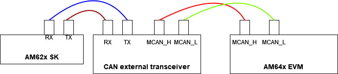
To connect the CAN external transceiver to AM62x CAN-FD controller, connect pin 8 (MCAN0_RX) and pin 9 (MCAN0_TX) from AM62x User Expansion Connector to pin 1 (CAN_TX) and pin 2 (CAN_RX) on the CAN external transceiver. The CAN external transceiver will then need to be powered, connect 3.3V and GND pins to a power supply.
To test the CAN node consisting of AM62x CAN-FD controller and the CAN external transceiver, we will be connecting a AM64x EVM to the CAN external transceiver according to the following diagram:

Taking the CAN external transceiver and the AM64x EVM, connect pin 1 (CANL) and pin 2 (CANH) on the Header 2 of the CAN external transceiver to pin 3 (MCAN0_L) and pin 1 (MCAN0_H) located on the AM64x’s J31 connector.
The following images show how the final setup should look like:

|

|
| AM62x and external transceiver | AM64x receving CAN packets from AM62x |
6.1.5.4. Enable Device Tree Overaly on AM62x
Since the AM62x does not have an on-board CAN-FD transceiver there is no transceiver node on the AM62x Device Tree Source file; k3-am625-evm.dts. However a device tree overlay named k3-am625-sk-mcan.dtbo supported in the TI SDK which can be used to dynamically overlay the AM62x Device Tree. If an AM62x .wic image was flashed to an SD card, the k3-am625-sk-mcan.dtbo should be found in the root partition. This overlay can be loaded by stopping AM62x bootup during U-boot and executing the following commands:
Hit any key to stop autoboot:  0
=>
=> setenv name_overlays k3-am625-sk-mcan.dtbo
=> boot
6.1.5.5. Testing MCAN on AM62x
With all the boards powered on and the AM62x SK and AM64x EVM booted to Linux, the following commands could be executed to test CAN functionality.
- Setup AM64x to display received frames
root@am64xx-evm:~# ip link set can0 down
root@am64xx-evm:~# ip link set can0 type can bitrate 125000
root@am64xx-evm:~# ip link set can0 up
[   40.940389] IPv6: ADDRCONF(NETDEV_CHANGE): can0: link becomes ready
root@am64xx-evm:~# candump can0
[   47.533511] can: controller area network core
[   47.538112] NET: Registered protocol family 29
[   47.555073] can: raw protocol
can0  123   [4]  DE AD BE EF
[  138.824591] Initializing XFRM netlink socket
[  140.303978] bridge: filtering via arp/ip/ip6tables is no longer available by default. Update your scripts to load br_netfilter if you need this.
[  140.321844] Bridge firewalling registered
[  141.457406] process 'docker/tmp/qemu-check709863015/check' started with executable stack
Note: Use Ctrl-C to terminate candump
- Setup AM62x to transfer packets:
# To send:
root@am62xx-evm:~# ip link set can0 down
root@am62xx-evm:~# ip link set can0 type can bitrate 125000
root@am62xx-evm:~# ip link set can0 up
root@am62xx-evm:~# cansend can0 123#DEADBEEF
[ 1392.577915] can: controller area network core
[ 1392.582388] NET: Registered protocol family 29
[ 1392.594650] can: raw protocol
root@am62xx-evm:~#
For more MCAN driver instructions, go to MCAN.