Introduction
This ethernet TSN example illustrates the usage of gPTP IEEE 802.1AS stack with CPSW peripheral, in gPTP End-Point time_transmitter mode (i.e. master mode).
However, application used here supports all the below modes-
- gPTP End-Point time_transmitter mode (i.e. master mode)
- gPTP End-Point time_receiver mode (i.e. slave mode)
- gPTP Bridge mode
In this example, ptp4l on connected Host PC is configured to force gPTP time_receiver mode, so that the DUT becomes time_transmitter (i.e. gPTP master) mode. Yang based configuration is also supported. Currently File System is not supported, will be added in future releases.
See also :Ethernet TSN and gPTP Stack - API and Integration Guide
Supported Combinations
| Parameter | Value |
| CPU + OS | r5fss0-0_freertos |
| Toolchain | ti-arm-clang |
| Board | am64x-evm |
| Example folder | examples/networking/tsn/gptp_cpsw_app |
Steps to Run the Example
Prerequisites
- EVM Board
- Cat6 ethernet cable
- PC with Linux Ubuntu OS (or any PC running bash shell) and PTP capable network card
- Install
linuxptp $ sudo apt-get install linuxptp
$ ptp4l -v
- Configure linuxptp
$ wget https://raw.githubusercontent.com/richardcochran/linuxptp/master/configs/gPTP.cfg -O ~/gptp_config.cfg
- Attention
- Change the value of
priority1 in ~/gptp_config.cfg file to 255 to enforce PC to gPTP slave
-
For some network cards, there is a bug with internal propagation delay. So, in those cases you might need to increase the
neighborPropDelayThresh in ptp_config.cfg as below-
$ cat ~/gptp_config.cfg
\#
\# 802.1AS example configuration containing those attributes which
\# differ from the defaults. See the file, default.cfg, for the
/# complete list of available options.
/#
[global]
gmCapable 1
priority1 255
priority2 248
logAnnounceInterval 0
logSyncInterval -3
syncReceiptTimeout 3
neighborPropDelayThresh 10000
min_neighbor_prop_delay -20000000
assume_two_step 1
path_trace_enabled 1
follow_up_info 1
transportSpecific 0x1
ptp_dst_mac 01:80:C2:00:00:0E
network_transport L2
delay_mechanism P2P
priority1 in ~/gptp_config.cfg file can be changed to make the Linux PC master or slave. Lower the number higher the priority to become master.
Build the example
- When using CCS projects to build, import the CCS project for the required combination and build it using the CCS project menu (see Using SDK with CCS Projects).
- When using makefiles to build, note the required combination and build using make command (see Using SDK with Makefiles)
HW Setup
- Note
- Make sure you have setup the EVM with cable connections as shown here, EVM Setup. In addition do below steps.
AM64X-EVM
For CPSW based example
- Connect a ethernet cable to the EVM from host PC as shown below
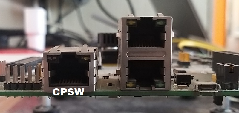
Ethernet cable for CPSW based ethernet
PPS Output
PPS output is a square wave signal generated by the device. It is used for comparison between the TT (master) and TR( slave) nodes when they are time synchronized. On the device, PPS is generated on the SYNC_OUT signal pin from CPTS (Common Platform Time Synchronization) of CPSW.
Out of box configuration for PPS signal output of this example is as follow:
| EVM | Mapped Signal Name | SOC Pin Name | PPS frequency | Output |
| am64x-EVM | PRG0_PRU0_GPO17 | U1 | 3.814 KHz | Pin B8 on J2 (i.e PIN8 on J2B) connector |
| am243x-EVM | PRG0_PRU0_GPO17 | U1 | 3.814 KHz | Pin B8 on J2 (i.e PIN8 on J2B) connector |
| am243x-LP | MMC1_DAT2 | K20 | 3.814 KHz | Pin3 on J6 connector |
| am263x-CC | SFDM0_CLK1 | A16 | 3.814 KHz | Pin4 on J6 connector |
| am263x-LP | SFDM0_CLK1 | A16 | 3.814 KHz | Pin4 on J6 connector |
To set/modify configuration of PPS signal , you may follow the below steps:
- Configure the bitSelect in EnetApp_enableTsSync() function in tsnapp_cpsw_main.c file. If bit n is selected, 2^(n+1) nano seconds is the time period of the square wave. Please note bitSelect starts from bit 17 which corresponds to 3.814 KHz.
- Configure pinmux for PPS Output signal under ENET(CPSW)->'pinmux Config'->'CPTS0_TS_SYNC(CPTS0_TS_SYNC)' and select the appropriate pin as per your EVM.

Figure: Syscfg tool CPSW pinmux changes to select PPS signal pin
- Signal is generated on the above configured PIN. You may connect oscilloscope on the pin to visualize and compare. One sample signal captured using oscilloscope. Blue from gPTP TT (master) and purple is from gPTP TR (slave)

Figure: Signal captured on oscilloscope
Create a network between EVM and host PC
EVM and PC has to connected directly as shown below using CAT6 or CAT5 cable. If there is ethernet switch placed in between, make sure the switch is gPTP capable.

Local network between PC and EVM
PORT1 instead of PORT0 on EVM can be used as well.
Run the example
- Attention
- If you need to reload and run again, a CPU power-cycle is MUST
- Launch a CCS debug session and run the example executable, see CCS Launch, Load and Run
- Connect board and PC as mentioned in "HW Setup" above.
- Execute the below command in PC terminal:
$ sudo ptp4l -i eno1 -m -l 6 -q -f ~/gptp_config.cfg
- You will see logs in the UART terminal as shown in the next section. PC side logs are with Intel i210 card.
Sample Log Output
DUT output
==========================
gPTP App
==========================
Enabling clocks!
sitara-cpsw: Create RX task for regular traffic
start to open driver.
EnetAppUtils_reduceCoreMacAllocation: Reduced Mac Address Allocation for CoreId:1 From 4 To 2
Init all configs
----------------------------------------------
sitara-cpsw: init config
Mdio_open:294
sitara-cpsw: Open port 1
EnetPhy_bindDriver:1717
sitara-cpsw: Open port 2
EnetPhy_bindDriver:1717
PHY 3 is alive
PHY 15 is alive
initQs() txFreePktInfoQ initialized with 16 pkts
MAC port addr: f4:84:4c:fb:c0:42
unibase-1.1.5
app_start:gptp start done!
INF:def04:simpledb_open:no data is imported
INF:def04:uc_hwal_open:
INF:cbase:cb_rawsock_open:dmaTxChId=0 dmaRxChId=0 nTxPkts=16 nRxPkts=32 pktSize=1536
INF:cbase:Mac addr has not been allocated
INF:def04:000000-082196:uniconf_main:uniconf started
gptp_task: started.
gptp_task: dbname=INF:def04:get_exmodid_in_db:first xl4gptp:exmodid=0
INF:gptp:gptpman_run:max_domains=1, max_ports=2
INF:cbase:cb_rawsock_open:dmaTxChId=1 dmaRxChId=1 nTxPkts=16 nRxPkts=32 pktSize=1536
INF:cbase:Mac addr has not been allocated
INF:gptp:dev:tilld0 open success
INF:gptp:dev:tilld1 open success
INF:gptp:gptpnet_init:Open lldtsync OK!
INF:gptp:IEEE1588-2019 performance monitoring enabled.
INF:gptp:onenet_activate:tilld0 status=0, duplex=0, speed=0Mbps
INF:gptp:onenet_activate:tilld1 status=0, duplex=0, speed=0Mbps
INF:gptp:000000-250071:domainIndex=0, GM changed old=00:00:00:00:00:00:00:00, new=F4:84:4C:FF:FE:FB:C0:42
INF:gptp:gptpclock_set_gmsync:gptpInstanceIndex=0, domainIndex=0, gmstate=2
INF:gptp:set_phase_offsetGM:domainIndex=0, New adjustment(New GM?)
Cpsw_handleLinkUp:1449
MAC Port 1: link up
INF:gptp:index=1 speed=1000, duplex=full, ptpdev=tilld0
WRN:gptp:000004-750003:waiting_for_pdelay_interval_timer_proc:portIndex=1, sourcePortIdentity=68:05:CA:FF:FE:C8:7A:C2, thisClock=F4:84:4C:FF:FE:FB:C0:42, neighborPropDelay=201
INF:gptp:waiting_for_pdelay_interval_timer_proc:portIndex, not asCapable
INF:gptp:md_pdelay_resp_sm_recv_req:port=1, set receivedNonCMLDSPdelayReq=1
5. 60s : CPU load = 5.52 %
INF:gptp:waiting_for_pdelay_interval_timer_proc:set asCapableAcrossDomains, portIndex=1
INF:gptp:set asCapable for domainIndex=0, portIndex=1
INF:gptp:000005-759829:gptpgcfg_set_asCapable:domainInde=0, portIndex=1, ascapable=1
INF:gptp:000005-768267:gm_stable:gm_unstable_proc:domainIndex=0
INF:gptp:gptpclock_set_gmsync:gptpInstanceIndex=0, domainIndex=0, gmstate=1
INF:gptp:000005-779851:gm_stable:gm_unstable_proc:domainIndex=0
INF:gptp:000005-874389:setSyncTwoStep_txSync:domainIndex=0, portIndex=1, sync gap=5874msec
INF:gptp:000005-879959:setFollowUp_txFollowUp:domainIndex=0, portIndex=1, fup gap=5879msec
INF:gptp:000006-875607:gm_stable:gm_stable_proc:domainIndex=0
INF:gptp:gptpclock_set_gmsync:gptpInstanceIndex=0, domainIndex=0, gmstate=2
domain=0, offset=0nsec, hw-adjrate=0ppb
gmsync=true, last_setts64=0nsec
10. 61s : CPU load = 4.36 %
15. 62s : CPU load = 3.99 %
domain=0, offset=0nsec, hw-adjrate=0ppb
gmsync=true, last_setts64=0nsec
20. 63s : CPU load = 4.11 %
25. 64s : CPU load = 3.97 %
domain=0, offset=0nsec, hw-adjrate=0ppb
gmsync=true, last_setts64=0nsec
30. 65s : CPU load = 4.11 %
35. 66s : CPU load = 4.11 %
40. 67s : CPU load = 4.01 %
PC Output
ptp4l[8056.842]: selected /dev/ptp0 as PTP clock
ptp4l[8056.892]: port 1: INITIALIZING to LISTENING on INIT_COMPLETE
ptp4l[8056.892]: port 0: INITIALIZING to LISTENING on INIT_COMPLETE
ptp4l[8059.849]: port 1: link down
ptp4l[8059.849]: port 1: LISTENING to FAULTY on FAULT_DETECTED (FT_UNSPECIFIED)
ptp4l[8059.871]: selected local clock 6805ca.fffe.c87ac2 as best master
ptp4l[8059.871]: assuming the grand master role
ptp4l[8062.744]: port 1: link up
ptp4l[8062.784]: port 1: FAULTY to LISTENING on INIT_COMPLETE
ptp4l[8066.197]: port 1: LISTENING to MASTER on ANNOUNCE_RECEIPT_TIMEOUT_EXPIRES
ptp4l[8066.197]: selected local clock 6805ca.fffe.c87ac2 as best master
ptp4l[8066.197]: assuming the grand master role
ptp4l[8066.699]: port 1: new foreign master f4844c.fffe.fbc042-1
ptp4l[8068.699]: selected best master clock f4844c.fffe.fbc042
ptp4l[8068.699]: port 1: MASTER to UNCALIBRATED on RS_SLAVE
ptp4l[8069.078]: port 1: UNCALIBRATED to SLAVE on MASTER_CLOCK_SELECTED
ptp4l[8069.700]: rms 3879921009606 max 7759842019460 freq -34943 +/- 7727 delay 200 +/- 0
ptp4l[8070.700]: rms 2254 max 3442 freq -27102 +/- 3073 delay 199 +/- 0
ptp4l[8071.700]: rms 3762 max 3942 freq -20229 +/- 1002 delay 198 +/- 0
...
...
ptp4l[8087.700]: rms 9 max 15 freq -20755 +/- 7 delay 199 +/- 0
ptp4l[8088.700]: rms 7 max 11 freq -20750 +/- 5 delay 200 +/- 0
See Also
Ethernet And Networking | Ethernet TSN CPSW gPTP Bridge Example | Ethernet TSN CPSW gPTP TimeReceiver (gPTP Slave) Example | Ethernet TSN CPSW gPTP TimeTransmitter (gPTP Master) Example | Ethernet TSN and gPTP Stack - API and Integration Guide
 1.8.20