Introduction
This package includes the Radio Test Library(RTLib) with a simple application example.
The Radio Test Library is used to communicate with a CC26xx/CC13xx radio device.
The library supports a number of test features:
- Link test with configurable packets and number of packets to be sent
- Continuous TX
- Continous RX
- Reading of RSSI value on receiver.
- Reading of Frequency Offset on receiver.
- Program flash from file. Several file formats are supported: .bin, .hex and .elf.
- Program flash from a data buffer.
- Read memory from the target device.
- Write non-flash memory on the target device.
- Warning
- The RTLib API may be subject to changes.
The changes will be described in the Revision History and the application examples will be updated accordingly.
The application examples does not contain all the devices that are supported. It is just intended as an example and it should be fairly simple to extend the examples with support for any of the ARM based devices supported by SmartRF Studio 7.
Device Support:
Radio Test library support CC26xx/CC13xx devices.
Emulator Support
The following emulators are supported:
- XDS100v3 (standalone and SmartRF06EB)
- XDS110
- XDS200
Folder structure
This package includes the following folders:
- bin: Application binaries and required DLL files.
- components: Includes drivers required for the application example.
- config: This folders includes device configuration files (XML files) and configuration files for the XDS100, XDS110 and XDS200 emulators.
- doc: Documentation for the package.
- ide: This folder includes project files for Visual Studio 2013.
- lib: Prebuilt library files.
- source: Header files for the library and source file for the application example.
Limitations
The RTLib library make use of the same libraries as SmartRF Studio 7 and SmartRF Flash Programmer 2 software. This is shown by the figure below.
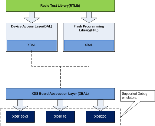
SmartRF Studio use the DAL library and the Flash Programmer use the FPL library. Both the DAL and FPL library are built as a "dll" file (dynamic loading) and each of the libraries have their own instance of the XBAL library (Static loading). To avoid losing time setting up a connection for both instances, special handling has been implemented where the XBAL instance from DAL is copied to the FPL instance.
When an instance of the RTLDevice is created, an instance of the DAL object will be created in the background. The DAL object loads a special FW image to target RAM that handles commands from DAL (for RF testing). When any of the FPL features are used, an FPL instance will be created and the XBAL instance from DAL will be copied. This happens in the background and the user does not have to think about it.
However, there are scenarios where the user must be aware of a time penalty. With the FPL features the user is free to do changes on the target device. For example writeMemory(). That means the state of the RAM FW handling DAL commands from DAL can no longer be guaranteed and the existing connection must be disconnected and a new connection must be made (new instance of the DAL object). This will all be handled in the background but a time penalty of about 4 - 5 seconds must be accepted.
It is recommended to do all RF test actions first and then do any flash programming actions at the end. The RTLDevice methods that use the FPL features will be marked with "FPL Feature".
API Reference Usage
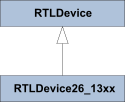
The library makes use of an object-oriented API. The API is defined with the attributes and methods (functions in C jargon) of a class hierarchy. The class hierarchy is used to encapsulate common methods and specialized methods. Currently, there is one base class and one subclass.
The base class RTLDevice defines the methods that will be common for all devices. Some of the methods are defined as pure virtual. In C++ that means the method is not implemented in the base class and must be implemented in the subclass. The base class is then a so called "Abstract class". This means it cannot be instantiated. The application using this library must create an instance of one of the subclasses.
The subclass RTLDevice26_13xx contains the specialized methods for the CC26xx and CC13xx family of devices.
The Class hierarchy:
The details for each class with their attributes and methods can be found under the "Classes" tag or by clicking on the class name in the code snippets given below.
Typical usage of the library
This description will give a general overview of the methods used in a typical Test case like sending a packet.
- Create an instance of the device object.
- Call method to enumerate connected devices. This must be done before any connection can be made.
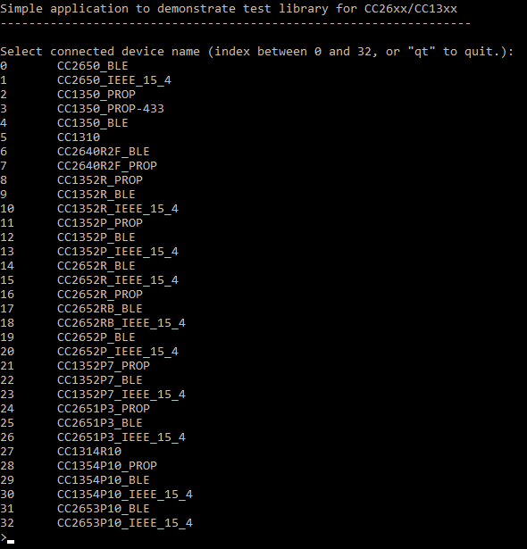
- Connect to the target device. The deviceName and devID Must be given as parameters. deviceName could be "CC2650_BLE", "CC2650_IEEE_15_4", "CC1350_BLE", "CC1350_PROP", CC1310"... The devId must be the same as one of the IDs returned by the enumeration.
pTestDevice->
connect(deviceName, devId);
- Set the packet data.
char pData[13] = {0xC,0,0xA,0,1,2,3,4,5,6,7,8,9};
- Read command settings from file. The data will be loaded from xml files and used to populate internal buffers with command data. To read the correct data, it is required to know the Test mode, the Category name, the Settings name and the Target name. The RTLDevice::TestConfig_t type is used to keep all these values.
- Test mode: See the definition of RTLDevice::TestConfig_t
- Category name: This is the same name as used in the list of typical settings from SmartRF Studio. The name can also be found in the configuration file ..\config\xml\<device name>\cmd_settings\categories.xml
- Settings name: The name of the xml file where the basic settings are defined. This name is also given in the categories.xml file.
- Target name: This is the same name as used in the drop down list of the Target Configuration in SmartRF Studio.
- Set parameter values if required. This can be used to overwrite some of the values loaded from the command settings. The parameter Name and Value will be used to calculate and set the appropriate command value.
- Set MCU registers if required. This could be if special IO pin configuration is required. The example below only show how to set one register value. A complete example can be found in the application example with configuration of the IO pins to control the ranges extender chip CC2592.
- Call function to initiate Packet TX. The function will execute the setting commands to configure the RF Device. This will typically be the "Radio Setup" command and the "Frequency Synth" command.
- Send packet. This can be one packet or several packets where the function is typically called within a loop.
Application Example
The application example illustrates how to use the Radio Test Library.
Prerequisites for compiling the application example:
How to run the prebuilt application example:
- Connect at least one device (For example CC26xx EM + XDS emulator). At least two devices must be connected for link test.
- Run the application executable located in the bin folder: "radio_test_lib_app_ex.exe"
- Select PHY mode:
- Select '0' (CC2650_BLE) for CC2650 BLE mode or CC2640
- Select '1' (CC2650_IEEE_15_4) for CC2650 IEEE 802.15.4 mode, CC2630 or CC2620
- Select '2' (CC1350_PROP) for CC1350 Sub-1 GHz proprietary mode
- Select '3' (CC1350_PROP-433) for LAUNCHXL-CC1350-4 proprietary mode
- Select '4' (CC1350_BLE) for CC1350 BLE mode
- Select '5' (CC1310) for CC1310 Sub-1 GHz proprietary mode
- Select '6' (CC2640R2F_BLE) for CC2640R2F BLE mode
- Select '7' (CC2640R2F_PROP) for CC2640R2F PROP mode
- Select '8' (CC1352R_PROP) for CC1352R Sub-1 GHz proprietary mode
- Select '9' (CC1352R_BLE) for CC1352R BLE mode
- Select '10' (CC1352R_IEEE_15_4) for CC1352R1 IEEE 802.15.4 mode
- Select '11' (CC1352P_PROP) for CC1352P Sub-1 GHz proprietary mode
- Select '12' (CC1352P_BLE) for CC1352P BLE mode
- Select '13' (CC1352P_IEEE_15_4) for CC1352P IEEE 802.15.4 mode
- Select '14' (CC2652R_BLE) for CC2652R BLE mode
- Select '15' (CC2652R_IEEE_15_4) for CC2652R1 IEEE 802.15.4 mode
- Select '16' (CC2652R_PROP) for CC2652R Sub-1 GHz proprietary mode
- Select '17' (CC2652RB_BLE) for CC2652RB BLE mode
- Select '18' (CC2652RB_IEEE_15_4) for CC2652RB IEEE 802.15.4 mode
- Select '19' (CC2652P_BLE) for CC2652P BLE mode
- Select '20' (CC2652P_IEEE_15_4) for CC2652P IEEE 802.15.4 mode
- Select '21' (CC1352P7_PROP) for CC1352P7 Sub-1 GHz proprietary mode
- Select '22' (CC1352P7_BLE) for CC1352P7 BLE mode
- Select '23' (CC1352P7_IEEE_15_4) for CC1352P7 IEEE 802.15.4 mode
- Select '24' (CC2651P3_PROP) for CC2651P3 Sub-1 GHz proprietary mode
- Select '25' (CC2651P3_BLE) for CC2651P3 BLE mode
- Select '26' (CC2651P3_IEEE_15_4) for CC2651P3 IEEE 802.15.4 mode
- Select '27' (CC1314R10) for CC1314R10 Sub-1 GHz proprietary mode
- Select '28' (CC1354P10_PROP) for CC1354P10 Sub-1 GHz proprietary mode
- Select '29' (CC1354P10_BLE) for CC1354P10 BLE mode
- Select '30' (CC1354P10_IEEE_15_4) for CC1354P10 IEEE 802.15.4 mode
- Select '31' (CC2653P10_BLE) for CC2653P10 BLE mode
- Select '32' (CC2653P10_IEEE_15_4) for CC2653P10 IEEE 802.15.4 mode
- Press Enter
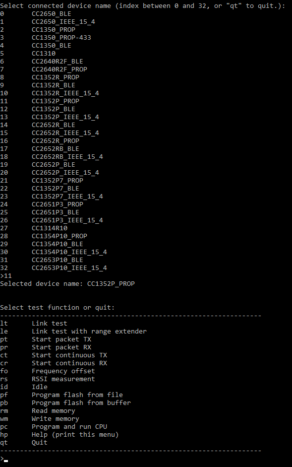
- Select test mode.
- Select 'lt' for Link test. This requires at least two devices connected.
- Select 'ct' for Continuous TX. Requires one device connected.
- Select devices for the test (device index).
- For the link test a device index for RX and a device index for TX must be selected.
- For the Continuous TX one device index must be selected.
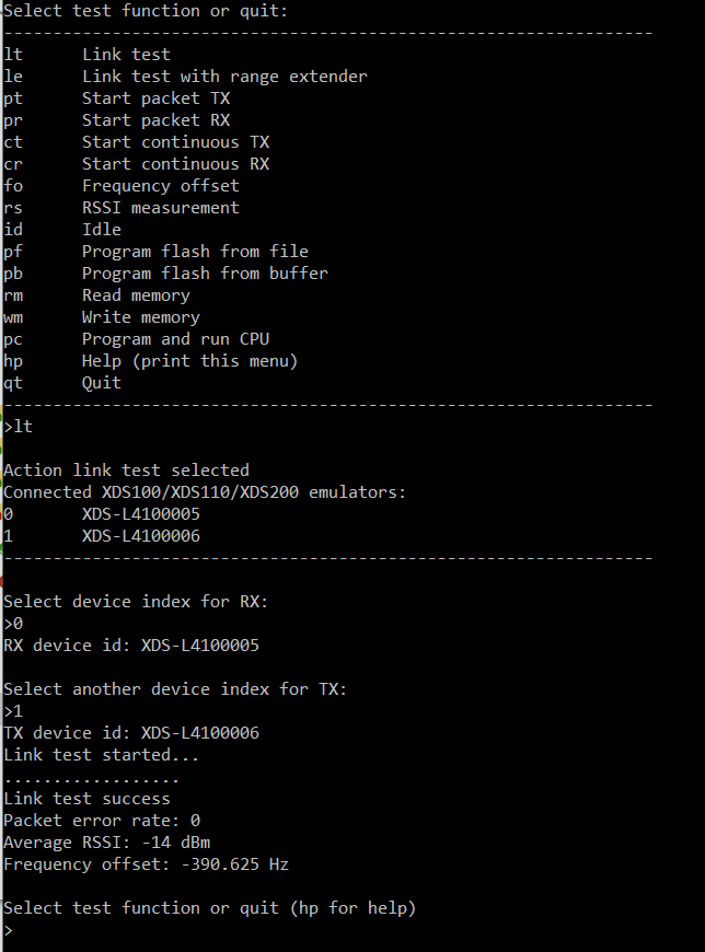
- Output after running link test successfully:
How to compile the application example:
- Run the qmake_app_ex.bat from the command window that is provided on the Windows Start-up menu by Qt. This ensures that the environment is set correctly.
Go to the folder ..\ide\windows\msvc2015\radio_test_lib_app_ex and start qmake_app_ex.bat. This will create the project files for MS Visual Studio 2015.
The project files are already provided by the installer, but these files have been created on our build server and the environment is most probably different from the standard desktop installation of Qt. Therefore qmake_app_ex.bat is needed to set this right.
- Open Visual Studio 2015 and open the project file: radio_test_lib_app_ex.vcxproj (..\ide\windows\msvc2015\radio_test_lib_app_ex)
- Right click on "radio_test_lib_app_ex" in the solution explorer pane and select Rebuild.
Troubleshooting
Compilation Error
Symptom:
Compilation fails with the message: fatal error C1083: Cannot open include file: 'QCoreApplication': No such file or directory
Cause:
The path to the include files is not correct.
Solution:
Remember to run qmake as described in the "How to compile" section.
Runtime Error:
Symptom:
Connecting to device failed: Error: File open failed.
Cause:
This error occur when the application fail to open the XDS emulator board file when trying to connect to the device.
Solution:
In most cases this is caused by the working directory in debug mode is not set correctly. The working directory can be set within the Visual Studio IDE. Right click on the project and select "Properties". Then select the "Debugging" option. The option "Working Directory" should be changed from "$(ProjectDir)" to "$(OutDir)"
Runtime Error:
Symptom:
Device access failed: XBAL: Board reset before connect failed
Cause:
The RTLib application example will report "Error: Device access failed: XBAL: Board reset before connect failed" if XDS110 firmware is incompatible.
Solution:
To get around this, use SmartRF Studio to upgrade the XDS110 firmware.
Revision History
../revision_history/revision.html