4.12. MCAN
4.12.1. Introduction
The MCAN (Controller Area Network) module implements the CAN protocol with support for CAN 2.0 A, B and FD and enables seamless communication over a CAN bus. Each MCAN module supports flexible bit rates greater than 1 Mbps and is compliant to ISO 11898-1:2015. They connect to the physical layer of the CAN network through external (for the device) transceivers. The MCAN controller is responsible for message reception, transmission and management of the communication protocol. It supports both classic CAN and CAN FD (CAN with Flexible Data-Rate) specifications allowing a higher throughput and increased payload per data frame. The classic CAN and CAN FD devices can coexist on the same network without any conflict. It also provides advanced Error detection mechanisms to ensure reliable communication.
4.12.2. Features Supported
Conforms with CAN Protocol 2.0 A, B and ISO 11898-1:2015
Full CAN FD support (up to 64 data bytes)
Up to 32 dedicated Transmit Buffers
Configurable Transmit FIFO, up to 32 elements
Configurable Transmit Queue, up to 32 elements
Configurable Transmit Event FIFO, up to 32 elements
Up to 64 dedicated Receive Buffers
Two configurable Receive FIFOs, up to 64 elements each
Up to 128 filter elements
Internal Loopback mode for self-test
Maskable interrupts, two interrupt lines
Timestamp Counter
4.12.3. Test Setup
4.12.3.1. Internal Loopback
No Setup required
4.12.3.2. External Loopback
The GESI daughtercard is to be connected to J51 and J46 Expansion connectors on the board.
Connect MCAN instances using jumper wires.
For MCU1_0, MCU_MCAN0 and MCU_MCAN1 transceivers should be connected. These are J30 and J31 on the CPB.
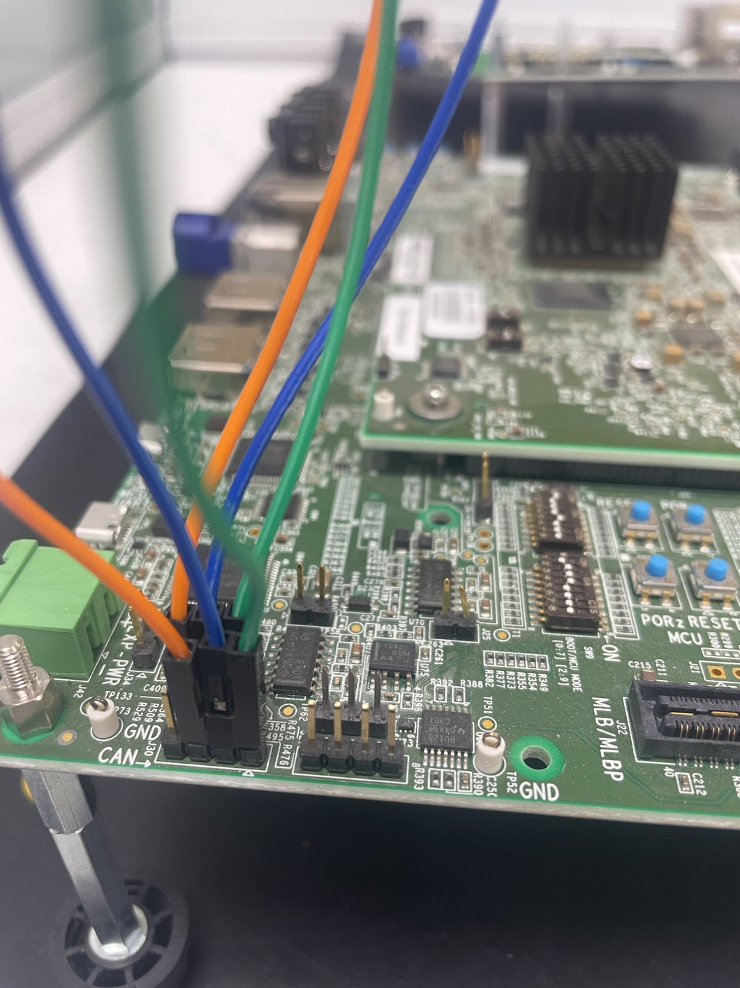
For MCU2_1, MAIN_MCAN4 and MAIN_MCAN5 should be connected. These are J12 and J14 on the GESI board.

4.12.3.3. Transmitter
Download PCAN-VIEW https://www.peak-system.com/PCAN-View.242.0.html?&L=1
Connect PCAN module to the MCAN instance specified in the Test Cases table above.
PCAN Connections

For MCU1_0
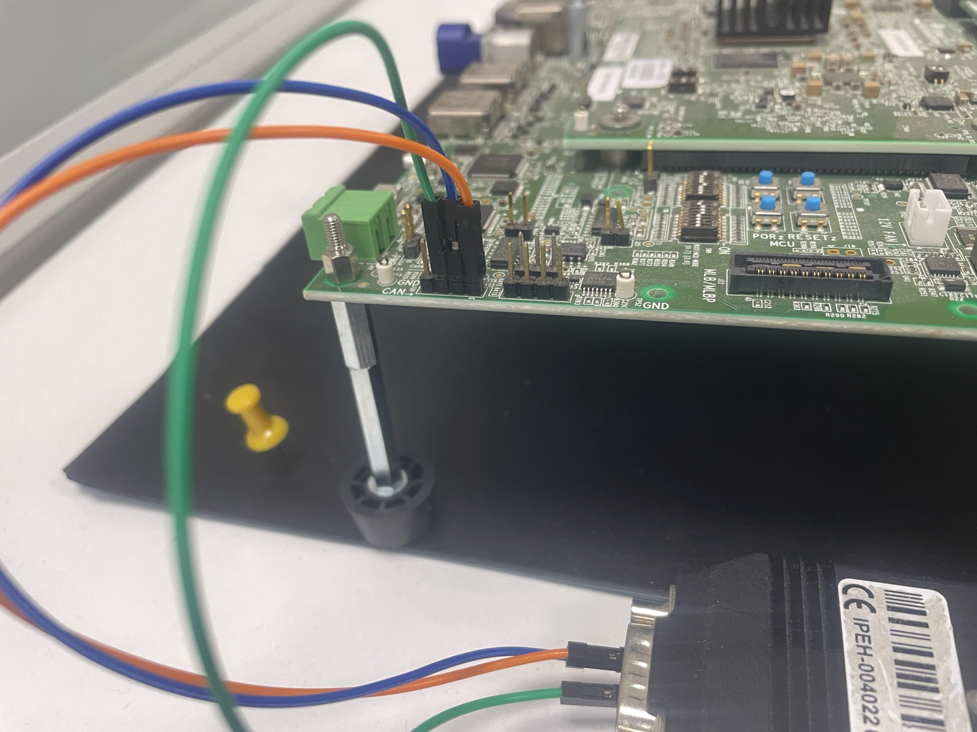
FOR MCU2_1

Connect PCAN Module in PCAN-View.
4.12.3.4. Receiver
Download PCAN-VIEW https://www.peak-system.com/PCAN-View.242.0.html?&L=1
Connect PCAN module to the MCAN instance specified in the Test Cases table above.
PCAN Connections
For MCU1_0

FOR MCU2_1
Connect PCAN Module in PCAN-View.
4.12.4. Applications
4.12.4.1. Examples
Name |
Description
|
Supported SOCs
|
|---|---|---|
MCAN Unit Test application |
Example comprises of various
testcases to test functionality
of the module using both Classic
CAN and CAN FD. It supports
internal loopback, receiver,
transmitter and B2B modes.
|
J721E
J721S2
J7200
|
MCAN EVM Loopback application |
Example operates as either
transmitter, receiver CAN
nodes. Also, supports digital
loop back mode.
With 2 boards, can be used to
emulate 2 node CAN network with
one as transmitter and the
other as receiver.
It also provides an External
Loopback test, where one MCAN
instance is configured as
transmitter and the other as
receiver on the same board.
In all modes, MCAN operates in
CAN-FD with arbitration bitrate
and data-phase bitrate set to
1 Mbps and 5 Mbps respectively.
|
J721E
J7200
J721S2
J784S4
|
4.12.4.2. Test Cases
Application |
Test Cases
|
Description
|
SOCs
|
Instances used
|
|---|---|---|---|---|
MCAN EVM Loopback Application |
Transmitter Test
|
Sends 15 messages
with varying payloads
between 1 byte to 64
butes.
|
J721E, J7200,
J721S2, J784S4
|
MCU1_0: MCU_MCAN0
MCU2_1: MAIN_MCAN4
|
Receiver Test
|
Receives 15 messages
with payload varying
from 1 byte to 64
bytes.
|
J721E, J7200,
J721S2, J784S4
|
MCU1_0: MCU_MCAN1
MCU2_1: MAIN_MCAN4
|
|
Internal Loopback
|
Sends and receives
15 messages with
payload varying from
1 byte to 64 bytes.
|
J721E, J7200,
J721S2, J784S4
|
MCU1_0: MCU_MCAN0
MCU2_1: MAIN_MCAN4
|
|
External Loopback
|
Sends and receives
15 messages with
payload varying from
1 byte to 64 bytes
externally from one
MCAN instance to
another.
|
J721E, J7200,
J721S2, J784S4
|
MCU1_0: MCU_MCAN0,
MCU_MCAN1
MCU2_1: MAIN_MCAN4
MAIN_MCAN5
|
|
MCAN Unit Test Application |
CAN FD Mode with
Bit Rate Switching
ON
|
Sends and receives
message, checks if
they match, checks if
Tx Event message
marker matches with
sent message,captures
Timestamp.
|
J721E
|
MCU1_0:
Default Module:
MCU_MCAN0
Default Rx Module:
MCU_MCAN1
|
Classic CAN Mode
|
Sends and receives
Classic CAN message
and checks if they
match.
|
J721E, J721S2
|
||
CAN FD Mode with
Bit Rate Switching
OFF
|
Sends and receives
message, checks if
they match.
|
J721E, J721S2
|
||
External Timestamp
|
Sends and receives
message, checks if
they match, checks if
Tx Event message
marker matches with
sent message,captures
Timestamp.
|
J721E, J721S2
|
||
High Priority
Messages
|
Sends and receives
high priority message
checks if they match.
|
J721E, J721S2
|
||
Internal Loopback
|
Sends and receives
messages in internal
loopback mode, checks
if they match.
|
J721E, J721S2
|
||
Tx Mixed Config.
With Buffer & FIFO
|
Uses both buffer and
FIFO to send and
receive messages,
checks if they match.
|
J721E, J721S2
|
||
Tx Mixed Config.
With Buffer &
Queue
|
Uses both buffer and
queue to send and
receive messages,
checks if they match.
|
J721E, J721S2
|
||
Throughput
|
Sends and Receives
messages, checks if
they match, measured
frames per seconds
should be 85% of the
theoretical.
|
J721E
|
||
ECC Test
|
In case of single bit
error, corrected data
is transmitted.
In case of double bit
error, message is not
transmitted.
|
J721E, J721S2
|
||
ECC Self(SEC) Test
|
In case of single bit
error, corrected data
is transmitted.
In case of double bit
error, message is not
transmitted.
|
J721E, J721S2
|
||
ECC Self(DED) Test
|
In case of single bit
error, corrected data
is transmitted.
In case of double bit
error, message is not
transmitted.
|
J721E, J721S2
|
||
DMA Events
|
Sends and Receives
messages, checks if
they match.
|
J721E, J721S2,
J7200
|
||
Programmable Bit
Rate
|
Sends and Receives
messages, checks if
they match.
|
J721E, J721S2
|
||
Node State
Transitions
|
MCAN shall transition
its states properly.
|
J721E
|
||
External Timestamp
Overflow Interrupt
|
Core shall receive
external time stamp
interrupt.
|
J721E, J721S2
|
||
Clock Stop Request
|
MCAN shall ACK back
clock stop request
|
J721E, J721S2
|
||
Time Stamp Counter
Reset
|
Time Stamp Counter
shall get reset after
calling TS Reset API.
|
J721E, J721S2
|
||
Bus Monitoring
Mode
|
Message over CAN
network is received
by MCAN but
transmitter node gets
ACK error.
|
J721E
|