Installation Steps
J721E/J7200/J721S2/J784S4/J742S2
MCUSW is a part of Foundation SDK RTOS and could be installed from that installer. No additional steps required. However, the MCAL configurator would require an additional step. Please refer (Getting access to MCAL) to receive installer for configurator and steps to obtain licese is detailed in (License for Configurator)
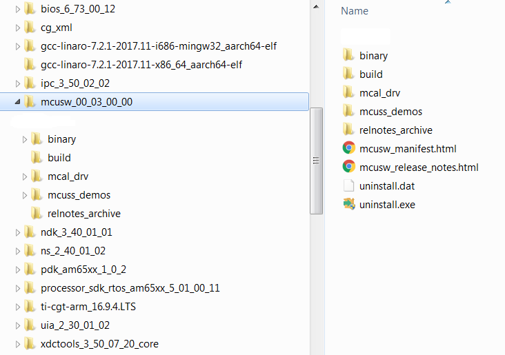
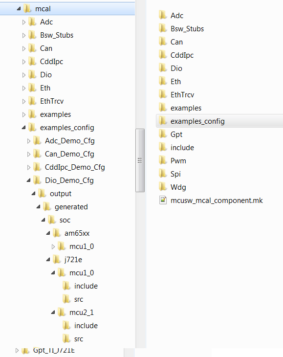
Directory structure post installation
Please note that this is an indicative image, actual versions would change
Back To Top
Directory Structure
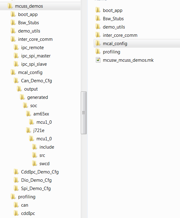
Post installation of MCUSW, the following directory would be created. Please note that this is an indicative snap-shot. Modules/Drivers could be added/modified.
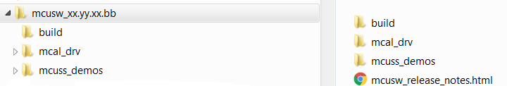
Top Level Directory Structure
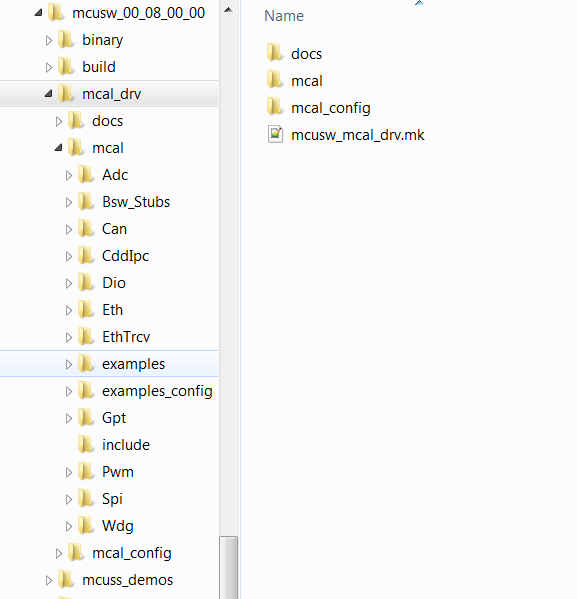
MCAL
MCAL Directory structure, contains MCAL modules, build files. Please note that this is an indicative snap-shot. Modules/Drivers could be added/modified.
Back To Top
MCAL Modules
MCAL Examples
Contains demo applications that demonstrate use of MCAL modules. An integrator could refer these to determine the dependencies of the module.
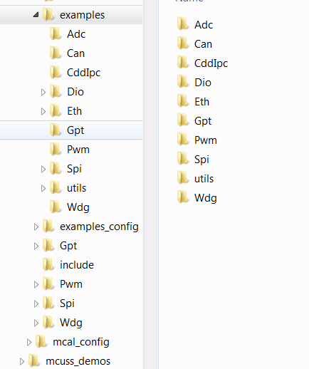
MCAL Examples
MCAL Examples Configuration
Contains configurations (standalone i.e. configuration for given module and its dependencies, such as Gpt (not dependent on other modules), Can (with Dio, etc...))
MCAL Example Configurations
Back To Top
Hardware Dependencies
MCU SW is supported on the boards/EVM listed below
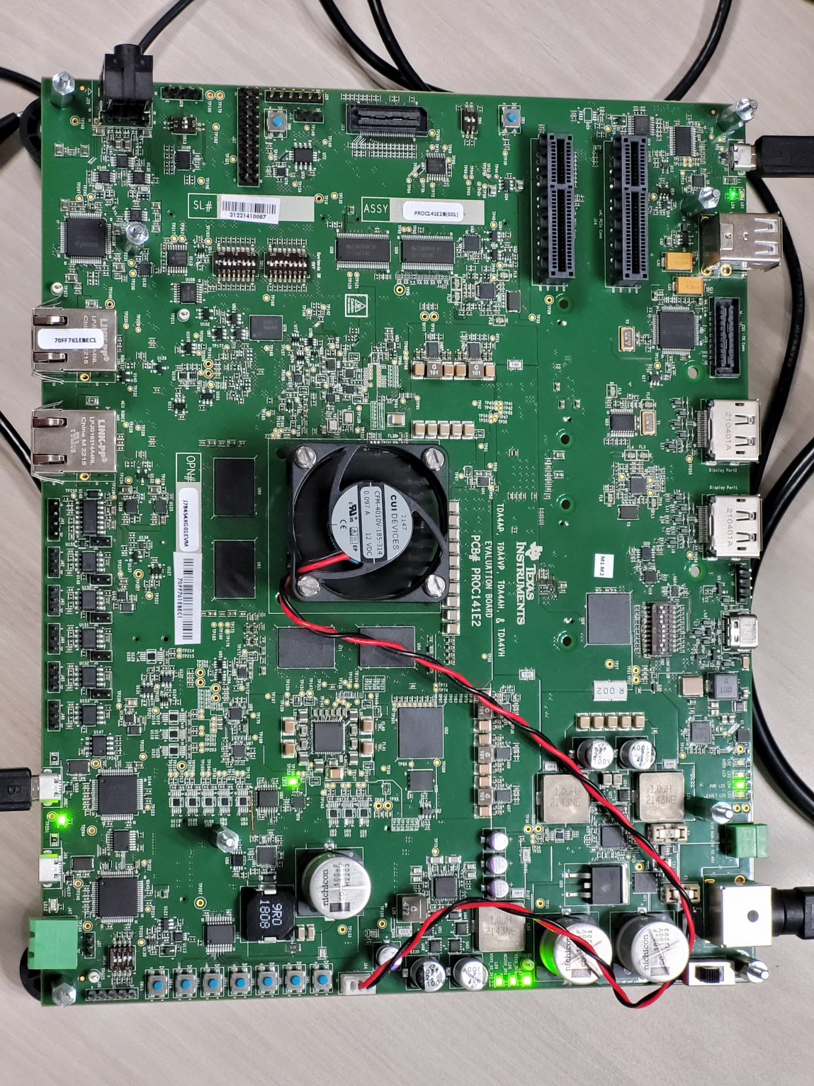
J721E EVM
Contact your FAE for documents describing the EVM
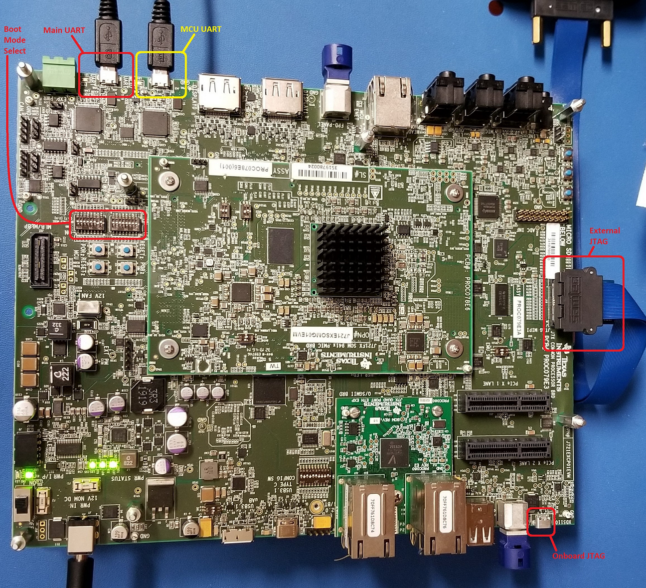
J721E EVM
J7200 EVM
Contact your FAE for documents describing the EVM 
J721S2 EVM
Contact your FAE for documents describing the EVM

J784S4 EVM
Contact your FAE for documents describing the EVM
J784S4 EVM
J742S2 EVM
Contact your FAE for documents describing the EVM

J742S2 EVM
J721E/J7200/J721S2 EVM NO Boot Mode / CCS
J721E NO Boot mode
J784S4/J742S2 EVM NO Boot Mode / CCS
J784S4/j742S2 NO Boot mode
J721E/J7200/J721S2 EVM MMC/SD Boot Mode
J721E MMC/SD Boot mode
J784S4/J742S2 EVM MMC/SD Boot Mode
J784S4/J742S2 MMC/SD Boot mode
J721E/J7200 EVM OSPI Boot Mode
J721E OSPI Boot mode
J721S2 EVM OSPI Boot Mode

J784S4/J742S2 EVM OSPI Boot Mode
J784S4/J742S2 OSPI Boot mode
Back To Top
MCU SS Demo
MCUSS Demonstration Applications
MCAL Dependencies
- Bsw_Stubs : BSW Stubs that would be required to implement MCAL based demo applications
- mcal_config : MCAL Driver Configurations
Utilities
- demo_utils : Utility functions
Demos
Please refer (MCU Demos) for more information on supported demo applications
Back To Top
Build
MCAL employs make based build mechanism. When building on Windows based machine, tool such as Cygwin could be used.
CCS folder should contain Cygwin, please see (Setup Build Environment) for more details.
Setup Build Environment
Following changes are required to be performed in Rules.make to build
- Rules.make can be found at ($SDK_INSTALL_PATH)/mcusw/build, When building on Windows environment ensure to update variables under ifeq (,Windows_NT)
- Choose to build either MCUSS Demo Applications or MCAL Examples
- MCUSS demo application no longer uses TI RTOS (sysBios), they only support freertos and MCAL do not use any OS
- Set BUILD_OS_TYPE = freertos to build MUCSS demo applications
- Set BUILD_OS_TYPE = baremetal to build MCAL examples/libraries
- Specify the location of the compiler
- Typically SDK package includes the required compiler
- In Rules.make, update SDK_INSTALL_PATH to specify location of the SDK installation.
- One can override compiler path by updating variable TOOLCHAIN_PATH_R5
- Enable / Disable logging messages to UART
- Flag MCUSW_UART_ENABLE, when set to TRUE directs the messages from example application to UART console. When set to FALSE, these messages are displayed in CCS console.
- Windows environment only
- All the required utils are provided with the CCS installation. If CCS is not installed, please download Cygwin and install it. Cygwin
- Ensure path gmake is included in windows environment variable Path Eg: C:/ti/ccs1010/ccs/utils/bin
- Specify location of the Cygwin utils, update utils_PATH in mcusw/build/Rules.make file. This utils is required for "rm" command. Eg: C:/ti/ccs1010/ccs/utils/cygwin
- OpenSSL installation is required for windows build. Easiest way for Windows users to install OpenSSL (if not already present) is to download and install Strawberry Perl. Ensure that the installed location of OpenSSL is added to Windows Environment Variables for a successful build.
- Note that MPU core builds (CORE=mpu1_0) are not supported in Windows setup.
If FoundationSDK is installed sucessfully, no specific changes are required to build. Please refer to Steps to build in windows to build MCAL examples.
To build for specific SoC, ensure using BOARD=j72xxx_evm and SOC=j72xx explicitly in each command. By default J721E is selected.
Example: gmake -s all BOARD=j7200_evm SOC=aj7200
Build Everything MCAL
With steps listed at (Setup Build Environment) all MCAL modules can be built
- Ensure BUILD_OS_TYPE = baremetal
- Go to folder ($SDK_INSTALL_PATH)/mcusw/build
- Linux make -s all and gmake -s all for Windows
- Linux make -s all CORE=mcu2_1 and gmake -s all CORE=mcu2_1 for Windows does not work, as default eth_app is not supported on core MCU2_1.
- Use BOARD=j721e_evm to build for J721E SOC(Linux make -s all BOARD=j721e_evm and gmake -s all BOARD=j721e_evm for Windows)
- Use BOARD=j7200_evm to build for J7200 SOC(Linux make -s all BOARD=j7200_evm and gmake -s all BOARD=j7200_evm for Windows)
- Do the same for j721s2_evm, j7200_evm
- Use option -j to speed up compilation (note that -j option is not recomended while building demos)
- On Successful compilation, binary folder would be created in ($SDK_INSTALL_PATH)/mcusw/binary/(driver name)_app/bin/j721e_evm OR ($SDK_INSTALL_PATH)/mcusw/binary/(driver name)_app/bin/j7200_evm
- Similarly, other devices builds are also enabled.
Build All Demos
With steps listed at (Setup Build Environment) completed MCAL modules can be built
- Go to folder ($SDK_INSTALL_PATH)/mcusw/build
J721E
- Can Profiling Application
- make -s can_profile_app BOARD=j721e_evm SOC=j721e BUILD_PROFILE=release CORE=mcu1_0 BUILD_OS_TYPE=freertos
- make -s can_profile_app BOARD=j721e_evm SOC=j721e BUILD_PROFILE=release CORE=mcu2_1 BUILD_OS_TYPE=freertos
- IPC Profiling Application
- make -s cdd_ipc_profile_app BOARD=j721e_evm SOC=j721e BUILD_PROFILE=release CORE=mcu1_0 BUILD_OS_TYPE=freertos
- make -s ipc_remote_app BOARD=j721e_evm SOC=j721e BUILD_PROFILE=release CORE=mcu2_1 BUILD_OS_TYPE=freertos
- On Successful compilation, binary folder would be created in ($SDK_INSTALL_PATH)/mcusw/binary/(driver name)_app/bin/j721e_evm
J7200
- Can Profiling Application
- make -s can_profile_app BOARD=j7200_evm SOC=j7200 BUILD_PROFILE=release CORE=mcu1_0 BUILD_OS_TYPE=freertos
- make -s can_profile_app BOARD=j7200_evm SOC=j7200 BUILD_PROFILE=release CORE=mcu2_1 BUILD_OS_TYPE=freertos
- IPC Profiling Application
- make -s cdd_ipc_profile_app BOARD=j7200_evm SOC=j7200 BUILD_PROFILE=release CORE=mcu1_0 BUILD_OS_TYPE=freertos
- make -s ipc_remote_app BOARD=j7200_evm SOC=j7200 BUILD_PROFILE=release CORE=mcu2_1 BUILD_OS_TYPE=freertos
- On Successful compilation, binary folder would be created in ($SDLINSTALL_PATH)/mcusw/binary/(driver name)_app_(BUILD_OS_TYPE)/bin/j7200_evm
- Similarly, build for other devices are also enabled.
Profiles
- Debug : Mostly used to development or debugging
- Release : Recommended to be used for production / profiling performance
Other useful commands
- To Clean all pdk libraries
- gmake -s pdk_allclean
- As MCUSW is dependent on PDK, if any changes done in PDK, please clean PDK and build MCUSW application again.
- To Clean all examples (all MCAL drivers and their associated examples) For J7200/J721S2/J784S4/J742S2, need to explicitly mention BOARD=j72xxx_evm SOC=j72xxx as by default J721E is selected.
- gmake -s allclean
- gmake -s allclean BOARD=j7200_evm SOC=j7200
- gmake -s allclean BOARD=j721S2_evm SOC=j721S2
- gmake -s allclean BOARD=j784S4_evm SOC=j784S4
- gmake -s allclean BOARD=j742S2_evm SOC=j742S2
- To Build all examples (all MCAL drivers and their associated examples) For J7200/J721S2/J784S4/J742S2, need to explicitly mention BOARD=j72xx_evm as by default J721E is selected.
- gmake -s all
- gmake -s all BOARD=j7200_evm SOC=j7200
- gmake -s all BOARD=j721S2_evm SOC=j721S2
- gmake -s all BOARD=j784S4_evm SOC=j784S4
- gmake -s all BOARD=j742S2_evm SOC=j742S2
- To build libraries only (only MCAL driver are built as library)
- gmake -s mcusw_libs
- gmake -s mcusw_libs BOARD=j7200_evm SOC=j7200
- gmake -s mcusw_libs BOARD=j721S2_evm SOC=j721S2
- gmake -s mcusw_libs BOARD=j784S4_evm SOC=j784S4
- gmake -s mcusw_libs BOARD=j742S2_evm SOC=j742S2
- To build specific example (associated MCAL driver will also be built)
- gmake -s can_app
- gmake -s can_app BOARD=j7200_evm
- gmake -s can_app BOARD=j721S2_evm
- gmake -s can_app BOARD=j784S4_evm
- gmake -s can_app BOARD=j742S2_evm
- Other examples adc_app, cdd_ipc_app, dio_app, eth_app, eth_virtmac_app, gpt_app, mcspi_app, pwm_app, wdg_app, fls_app, fls_app_dac, fls_app_indac and fls_app_xip, icu_app
- The above list is indicative and examples could be added/deleted
- To determine example name, refer makefile in subdirectory of ($SDK_INSTALL_PATH)/mcusw/mcal/examples/
- gmake -help, will list available target names
- gmake can_profile_app -s
- gmake can_profile_app -s BOARD=j7200_evm SOC=j7200
Examples Linker File (Select memory location to hold example binary)
The example applications use different memory and this could be changed/re-configured.
- linker_r5.lds defines the memory locations used by the MCAL examples.
- The linker file is specific to a device/core and available at mcusw/build/(device family name)/(core name)/linker_r5.lds
- linker_r5_freertos.lds defines the memory locations used by the MCU SS demo applications
- The linker file is specific to a device and available at mcusw/build/(device family name)/(core name)/linker_r5_freertos.lds
- In case of J721E, mcusw/build/j721e/mcu1_0/linker_r5_freertos.lds
- In case of J7200, mcusw/build/j7200/mcu1_0/linker_r5_freertos.lds
- Used for demo application that use FREERTOS, which would be hosted on MCU 1 0. In J721E for other cores, replace mcu1_0, with other cores e.g. mcu2_1
- Application Specific Linker command files
- Some applications require to use custom linker command files
- e.g. for low-latency memory accesses, can profile application uses custom linker command files
- These would be under the application overrides directory. e.g. for can profile application it would at mcusw/mcuss_demos/profiling/can/overrides/j721e/mcu1_0/linker_r5_sysbios.lds

- Memory that is used to hold, code, data impacts performance of the driver
- When placed in internal memory (such OCMRAM) best performance is noted
- It's recommended to place ISR code and other frequently used code/data in internal memory
Porting MCAL module example applications to other cores
This section below is applicable to SoC's that include one or more R5F CPU in main domain. By default the MCAL library could be built for all R5F cores in main domain. However, the example application will require to be ported. The table (Supported Drivers) lists examples that are supported in this release. One can refer the existing application supported on R5F (MCU 10 or MCU 21) as reference for updating the example. Please note that mcu2_0 core used below is just for demonstration purpose.
- Create a folder for the required core (e.g. mcu2_0) in $MCUSW_INSTALLATION_PATH/mcal_drv/mcal/examples_config/$Module_Demo_Cfg/output/generated/soc/j721e/mcu2_0
- Create module configuration using EB tresos tool and copy the generated code to the above path
- Create linker command file for the core to be supported, which is used to specify physical address for the executeables and add it here $MCUSW_INSTALLATION_PATH/build/j721e/mcu2_0
- Update the build mechanism to support required core (e.g. mcu2_0)
- In mcusw_mcal_component.mk, add required core to be supported in the CORELIST section present in $MCUSW_INSTALLATION_PATH/mcal_drv/mcal/mcusw_mcal_component.mk
- Eg: Update can_app__CORELIST = mcu1_0 mcu2_1 to can_app__CORELIST = mcu1_0 mcu2_0 mcu2_1
- Inter module dependencies
- If there are any inter module dependencies
- Ensure to port the dependent modules
- Eg: Can module example invokes Dio Api's to enable Can Transceiver.
- If module requires to operate in polled/main function mode, no more actions required. Skip to build and test.
- Updating the interrupt configuration
- Identify the interrupts that would be used on the core hosting MCAL/AUTOSAR
- Update the core specific StartUp function. All examples define a function named $Module_app_name_Startup ()
- Only the interrupt mapping requires an update (pin mux and others remain as is)
- Eg: Please refer $MCUSW_INSTALLATION_PATH/mcal_drv/mcal/examples/Can/soc/j721e/mcu2_1/CanApp_Priv.c
- Build Command
- Use command "gmake -s can_app BOARD=j721e_evm CORE=mcu2_0" to build example application on new core.
- Binary
- Binary is generated here $MCUSW_INSTALLATION_PATH/binary/can_app/bin/j721e_evm/can_app_mcu2_0_release.xer5f
- Contatt e2e/FAE for any further help.
Running Examples
IDE
CCS
Please refer (IDE (CCS)) for CCS and GEL setup
Load Example Binaries
Jacinto Family of Devices
- Ensure boot mode of the EVM is configured as described in (J721E/J7200/J721S2 EVM NO Boot Mode / CCS)
- UART / Console for demo application logs / messages
- J721E EVM had 2 UART ports
- UART port named MCU UART would be used when demo applications are hosted on MCU R5F (mcu 1 0)
- UART port named Main UART would be used when demo applications are hosted on MAIN R5F (mcu 2 1)
- Refer EVM Image at (J721E EVM)
- CCS Setup & Steps to run from CCS Refer the SDK Release Notes user guide for generic test setup details and steps to run the examples/demos using CCS/SBL.
- Reset MCU_Cortex_R5_0_0 core
- In core MCU_Cortex_R5_0_0, load binary (driver name)_app_mcu1_0_(release or debug).xer5f
- J721E MCAL Binaries is available at ($SDK_INSTALL_PATH)/mcusw/binary/(driver name)_app/bin/j721e_evm/
- Some of the example applications (ipc) would have more than 1 binaries. The name of the binaries specify the core that it's intended to hosted on
- Run example
- On Core MCU 2 1
- UART port on which prints are displayed is different, ensure to connect UART port named UART on the EVM
- J721E MCAL Binaries is available at ($SDK_INSTALL_PATH)/mcusw/binary/(driver name)_app/bin/j721e_evm/(driver name)_app_mcu2_1_(release or debug).xer5f
- Connect to MAIN_Cortex_R5_0_1
- Load binaries and run
- To run demo applications, please refer individual application notes (MCU Demos)
- Demo Application : Refer demo specific documentation for steps / care abouts (MCU Demos)
SBL
J721E/J7200/J721S2/J784S4/J742S2
SD/MMC
To build the SBL binary for SD/MMC, please use the following command:
$cd ($SDK_INSTALL_PATH)/pdk_jacinto_07_xx_xx/packages/ti/build
J721E : $make sbl_mmcsd_img BOARD=j721e_evm SOC=j721e
J7200 : $make sbl_mmcsd_img BOARD=j7200_evm SOC=j7200
Post compilation of SBL, the SBL binary can be found at ($SDK_INSTALL_PATH)/(pdk-install-folder)/packages/ti/boot/sbl/binary/(SOC)_evm/(boot-media)/bin/*.tiimage
To bo able to boot from SD card copy the following to the SD card boot partition (FAT32)
- Copy SBL binary sbl_mmcsd_img_mcu1_0_release.tiimage as tiboot3.bin
- Copy the tifs.bin form ($SDK_INSTALL_PATH)/(pdk-install-folder)/packages/ti/drv/sciclient/soc/V1/tifs.bin as tifs.bin in case of J721E
- Copy the tifs.bin form ($SDK_INSTALL_PATH)/(pdk-install-folder)/packages/ti/drv/sciclient/soc/V2/tifs.bin as tifs.bin in case of J7200
- Copy the tifs.bin form ($SDK_INSTALL_PATH)/(pdk-install-folder)/packages/ti/drv/sciclient/soc/V4/tifs.bin as tifs.bin in case of J721S2
- Copy the tifs.bin form ($SDK_INSTALL_PATH)/(pdk-install-folder)/packages/ti/drv/sciclient/soc/V6/tifs.bin as tifs.bin in case of J784S4/J742S2
- Copy the application from ($SDK_INSTALL_PATH)/mcusw/binary/(driver name)_app/bin/j721e_evm)/.*appimage to the SD card boot partition as app
- MMC SD: Ensure The bootmode switches are configured as described in (J721E/J7200/J721S2 EVM MMC/SD Boot Mode)
OSPI
Steps below highlight the steps required to programe OSPI with binary image
Software Prerequisites
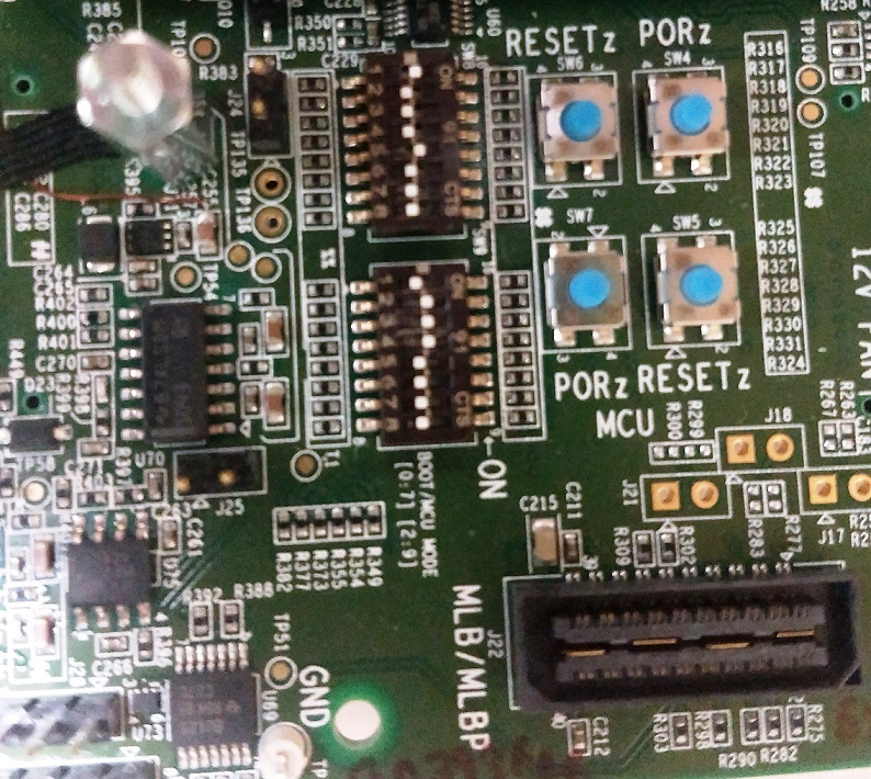
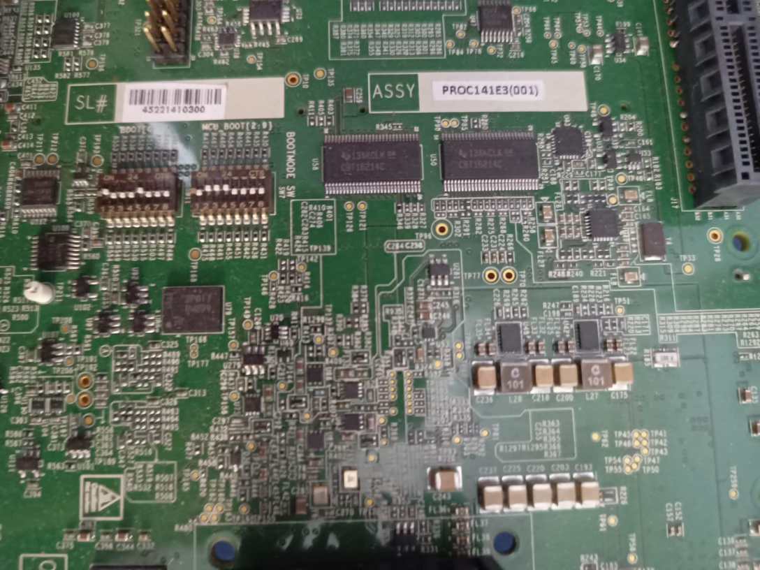
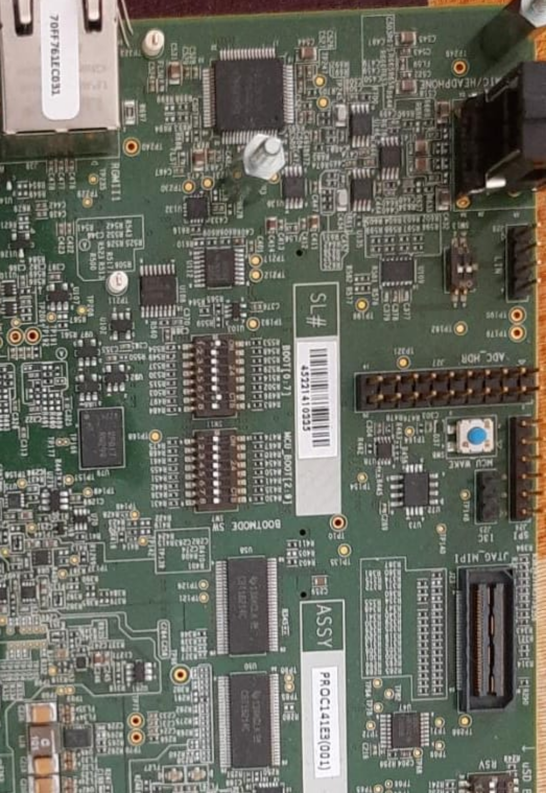
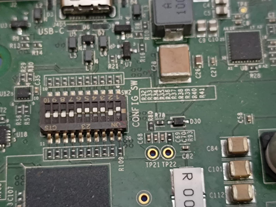
Board Setup for Flashing OSPI
- Configure SW3 on CP board for below values
1-OFF, 2-ON, 3-ON, 4-ON, 5-OFF, 6-OFF, 7-ON, 8-OFF, 9-ON, 10-OFF
- Configure Boot switches to 'UART' mode
SW8: 1-OFF, 2-OFF, 3-OFF, 4-OFF, 5-OFF, 6-OFF, 7-OFF, 8-OFF
SW9: 1-OFF, 2-ON, 3-ON, 4-ON, 5-OFF, 6-OFF, 7-OFF, 8-OFF
- Connect micro USB cable to MCU UART port (J43) and host PC – Confgure serial console application on host PC to use MCU UART port with '115200 8N1' configuration
Procedure for Flashing OSPI
- Load the uart flash writer binary uart_j721e_evm_flash_programmer_release.tiimage @ 0th location.
- Make sure the character 'C' is getting displayed on the serial console. Make a note of the COM port number.
- Close all the serial console applications on host PC, disconnect and reconnect micro USB cable connected to MCU UART port (J43)
- Run the below command to flash the SBL to OSPI flash dslite.bat –mode processors -c (COM Port#) -f (Boot Image) -d 3 -o 0
- Run the below command to flash the system firmware to OSPI flash dslite.bat –mode processors -c (COM Port#) -f (SYSFW Image) -d 3 -o 80000
- Run the below command to flash the app image to OSPI flash dslite.bat –mode processors -c (COM Port#) -f (App Image) -d 3 -o 100000
- Run the below command to flash OSPI PHY tuning binary. In case of J7200 flash at location 3FC0000 and for J721E at 3FE0000 dslite.bat –mode processors -c (COM Port#) -f (nor_spi_patterns.bin) -d 3 -o 3FE0000
Note : In Windows, during flashing if you get any error "Unknown response from the target", please disconnect and reconnect micro USB cable and then try to flash again. Note : For J7200 platform, during flashing please select from uniflash_6.1.0/processors/FlashWriter/j7200_evm/uart_j7200_evm_flash_programmer_release.tiimage.
Procedure for Verifying OSPI Boot
- After successful flashing, power OFF the board and configure it for OSPI boot.
- Connect micro USB cable to MCU UART port (J43) and host PC – Confgure serial console application on host PC to use MCU UART port with '115200 8N1' configuration
- Power ON the board and confirm the boot logs on serial console
| Mode | Switch Settings |
| UART | SW8: 0000_0000, SW9: 0111_0000 |
| OSPI (J721E) | SW8: 0000_0000, SW9: 0100_0000 |
| OSPI (J7200) | SW8: 1000_0010, SW9: 0011_0000 |
| OSPI (J721S2) | SW8: 0000_1010, SW9: 0110_0000 |
| OSPI (J784S4) | SW11: 0000_1010, SW7: 0110_0000 |
| OSPI (J742S2) | SW11: 0000_1010, SW7: 0110_0000 |
Back To Top
MCAL Compiler and Assembler Settings Information
This section provides an overview of the compiler and assembler settings required for MCAL product line deliverables. These settings are essential for ensuring that the code is optimized for performance, code size, and safety compliance.
| Category | Flag/Value | Description |
| Target Architecture | -mcpu=cortex-r5 | Targets the ARM Cortex-R5 processor. |
| -mfpu=vfpv3-d16 | Specifies the VFPv3-D16 FPU for floating-point operations. |
| -mthumb | Enables Thumb instruction set for smaller code size and efficient memory usage. |
| Optimization Levels | -Os | Optimizes for code size and execution speed; strikes a balance between binary size and performance. |
| Warning Suppressions | -Wno-unused-command-line-argument | Suppresses warnings for unused command-line arguments. |
| -Wno-unused-function | Suppresses warnings for unused functions. |
| -Wno-c++11-narrowing, -Wno-writable-strings | Handles compatibility with older or specific C++ features. |
| Error Handling | -Werror | Treats all warnings as errors, enforcing strict code quality. |
| Linker Flags | --ram_model | Configures the linker to optimize for execution from RAM. |
| --reread_libs | Forces the linker to re-read libraries, ensuring all required symbols are available. |
| --diag_suppress=10083 | Suppresses specific linker diagnostics (e.g., warning codes). |
| Assembler Flags | -me | Specifies the endianness (-me for little-endian). |
| -g | Generates debugging information in the assembled output, useful for debugging. |
| -mthumb | Configures the assembler to use Thumb instructions, which generate compact and efficient code for embedded devices. |
| --diag_warning=225 | Converts diagnostic code 225 to a warning rather than an error. |
| Debug Symbols | -g | Enables debugging symbols in the compiled code, useful for stepping through code during debugging. |
Additional Flags and Their Descriptions
| Flag | Description |
-c | Disables linking. |
-qq | Super Quiet Mode. |
--endian=little | Configures the compiler for little-endian mode. |
-Wall | Enables most warning categories. |
-Wno | Disables the specified warning category. |
--abi=eabi | Specifies the application binary interface as ELF. |
--inline_recursion_limit | Limits the number of recursive inline expansions during compilation to avoid excessive code size. |
--symdebug:dwarf | Generates symbolic debug information in DWARF format. Used in arxml files. |
--embed_inline_assembly | Embeds inline assembly in the generated code for optimization. |
-os | Interlists optimizer comments with assembly statements. |
--optimize_with_debug | Fully optimizes code while retaining debug information. |
-DBUILD_MCU1_0, -DBUILD_MCU2_0, -DBUILD_MCU1_1, -DBUILD_MCU2_1 | Identifies Core in the domain. |
-DSOC_J721E, -DSOC_J7200, -DSOC_J721S2, -DSOC_J784S4, -DSOC_J742S2 | Device Identifier for J7. |
-pdsw225 | Categorizes the diagnostic identified by num as a warning |
-march | direct the compiler to target a particular architecture |
-mv7R5 | Processor Architecture Cortex-R5 |
-mcpu | Select the target processor version. |
-mfpu | option to specify which floating-point hardware is available for use by the compiler |
-mfloat-abi | option in combination with the appropriate -mfpu option depending on what Arm processor variant is in use. |
-eo.oem4 | Output Object file extension |
-ea.sem4 | Output assembly file extension |
--float_support=vfplib | VFP coprocessor is enabled |
--emit_warnings_as_errors | Treat warning as errors |
-DBUILD_MCU | Identifies Domain |
-Xlinker | Required by TI Arm Clang |
--diag_suppress | Suppresses the diagnostic identified by num. |
--ram_model | option tells the linker to initialize variables at load time |
--reread_libs | option, you can force the linker to reread all libraries |
Note: Please note that all MCAL modules do not support this version. Please refer the release notes for details. Please note that both flags (-DAUTOSAR_421 & -DAUTOSAR_431) cannot be used simultaneously. These flags will be deprecated once all MCAL modules migrate to AUTOSAR Specificaion v4.3.1
Note: – is actually 2 "-" dashes they simply appear as one long dash in the user Guide.
Note: Define the appropriate -DSOC_xxx flag in the Makefile or environment based on the target device.
This ensures correct configuration is selected during the build. These flags are mandatory for proper compilation.
Detailed Descriptions
1. Target Architecture
The target architecture specifies the hardware environment for which the code is being built:
-mcpu=cortex-r5: This flag instructs the compiler to generate code optimized for the ARM Cortex-R5 CPU.-mfpu=vfpv3-d16: Enables support for the VFPv3-D16 floating-point unit.-mthumb: Generates code in the ARM Thumb instruction set, which is often used for its smaller instruction encoding, ideal for memory-constrained environments.
2. Optimization Levels
The optimization level impacts the performance and size of the generated code:
- **
-Os**: Optimizes for smaller code size while maintaining performance. This flag is a balance between binary size and execution speed, making it particularly suitable for embedded systems where memory is limited, but performance is still important.
3. Warning Suppressions
To maintain focus on relevant warnings, the following flags suppress less relevant warnings:
-Wno-unused-command-line-argument: Suppresses warnings for unused command-line arguments.- Additional C++ Flags: C++ builds use extra flags such as
-Wno-c++11-narrowing to handle potential issues arising from compatibility with C++11 features.
4. Error Handling
To ensure high code quality, **-Werror** is used, treating all warnings as errors, thus stopping the build until all warnings are resolved.
5. Linker Flags
The following linker flags are used to optimize memory handling:
- **
--ram_model**: Directs the linker to optimize for running the application from RAM.
- **
--reread_libs**: Ensures that the linker re-reads libraries to pick up required symbols.
- **
--diag_suppress=10083**: Suppresses specific diagnostic warnings, making the build output less cluttered.
6. Assembler Flags
The assembler flags are used when generating object files from .asm or .S assembly source files:
- **
-me**: Specifies the endianness, with -me indicating little-endian.
- **
-g**: Includes debugging symbols to help with debugging at the assembly level.
- **
-mthumb**: Uses Thumb instructions for efficient code generation.
- **
--diag_warning=225**: Converts the specified diagnostic into a warning, avoiding a build error.
7. Debug Symbols
The **-g** flag enables the inclusion of debugging symbols in the output, which are vital for troubleshooting during development. This flag is typically used for debug builds.
Note:
Avoid using **--scan_libs** linker flag as it may lead to redefinition of macro errors during the build as MCAL links MCU+SDK library.
MCAL Examples - Profile : Release
Same flags that were used for driver (Additional Flags and Their Descriptions), additional flags listed below
- UART_ENABLED : Configure example application to use UART / Console to display messages.
Steps to build in windows environment
By default CORE SDK RTOS JACINTO support to be built in Linux environment. All the required tools (compilers, OS, etc...) are packaged in CORE SDK RTOS, which enables MCUSW to built without any modifications.
The components MCUSW and PDK can be built in windows environment, with right version of tools.
List below details the steps required to build MCAL (MCUSW) examples in windows environment
Step 1 : Download the windows version of required tools
- CORE SDK RTOS JACINTO source is installed and accessible from windows machine, which would be used to build
- If there is windows_codegen_tools.tar.gz for a SDK, then download this one and skip next step. If not, please continue with next step.
- Download the windows version of the tools
Step 2 : Install tools and copy the components
- Unzip windows_codegen_tools.tar.gz or install the downloaded tools in ${Path}/CORE_SDK_RTOS_JACINTO_XXYYZZ/
- Ensure the version of downloaded tools match the versions used in CORE SDK RTOS
- Copy the components mcusw and pdk
- Ensure that the mcusw & pdk naming conventions is same as in CORE SDK RTOS
Step 3 : Disable generation of cust SBL
- Custom SBL is part of PDK package and relies on Linux based tools
- This requires to be excluded
- In file CORE_SDK_RTOS_JACINTO_XXYYZZ\pdk\packages\ti\boot\sbl\sbl_component.mk
- Comment out / delete
- sbl_lib_cust from sbl_LIB_LIST
- All statements under # SBL Custom LIB
- Without these steps the PDK library compilation would fail
Step 4 : Build
- Follow the steps listed in Build to build MCAL examples
Examples NOT supported in windows build
| Core | Examples Not Supported | Comments |
| MCU 1 0 | Multi-Core Boot Application | As demo reuqires Linux/QNX, C7x & C66 apps |
| MPU 1 0 | IPC Remote Client Application | Not Yet supported |
| MCU 1 0 | can_profile_xip_app | Creation of .bin image is not supported |
| MCU 1 0 | fls_xip | Creation of .bin image is not supported |
 1.8.15