|
MCUSW
|
|
MCUSW
|
This application demonstrates the fast boot capability provided by the Octal SPI flash controller on Jacinto SoCs. The application performs the following actions:
This facilitates an early CAN response feature, typically required in an automotive ECU, followed by booting of the main domain cores on the SoC.
Please refer to the data sheets for early CAN response
This application depends on multiple components:
This application depends on the Secondary Boot Loader (SBL) component from Processor SDK RTOS. For further details on the SBL, please refer to the Platform Development Kit (PDK) documentation on the SBL component for this release.
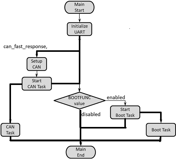
The following flow chart displays the main application on the MCU1_0, which can spawn up to 2 current tasks.
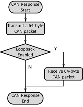
The following flow chart displays the functionality of the CAN task if the CAN function is set to "can_fast_response".
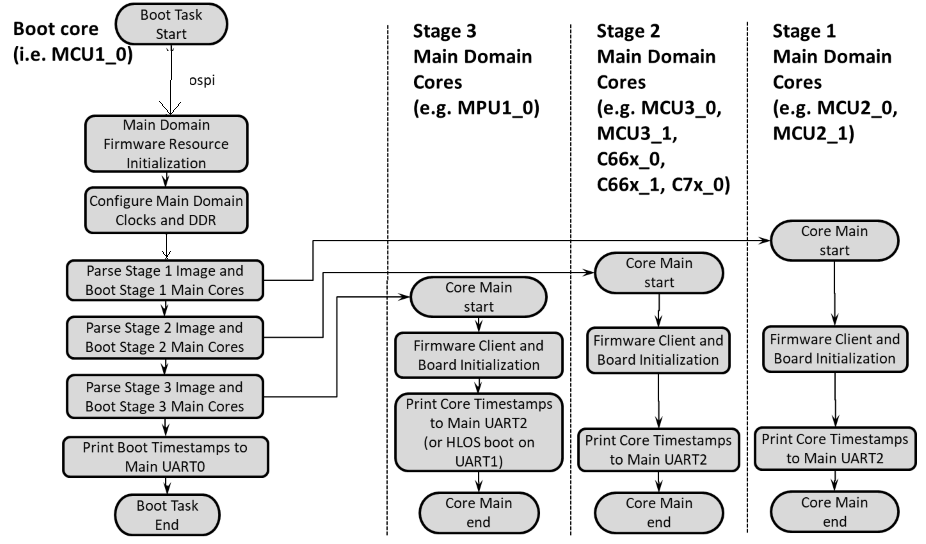
The following flow chart displays the functionality of the Boot task, as well as the applications started on the main domain cores.
The following flow chart displays the functionality of the Boot task when run along with BIST (as well as the applications started on the main domain cores). Note that the default build of this application disables the BIST thread shown below, and BISTFUNC flag must be enabled in the build for BIST to be run.

Enable/Disable Boot Task
The task that boots the main domain cores can be enabled/disabled. In the default boot sequence there are 3 stages for booting (J721E), (J721S2), (J784S4), or 2 stages (J7200). The specification of the cores to be included in each stage is given by the arrays "boot_order_first_stage", "boot_order_second_stage" and "boot_order_third_stage", found in mcuss_demos/boot_app_mcu_rtos/soc/$SOC/boot_core_defs.c. Below is the configuration flag for this feature.
Options are "enabled" (default) or "disabled".
Enable/Disable BIST Task (J721E only) The task that runs Logic BIST and Memory BIST prior to boot stages can be enabled/disabled. In the default BIST sequence, there is one "pre-boot" stage (for BIST sections that need to be run before booting any of the main domain cores) and 3 main stages where BIST is run for main domain cores prior to the Boot Task booting those particular cores. The specification of the cores to be included in each stage is given by the arrays "pbist_pre_boot_stage", "lbist_pre_boot_stage", "pbist_first_boot_stage", "lbist_first_boot_stage", "pbist_second_boot_stage", "lbist_second_boot_stage", "pbist_third_boot_stage", and "lbist_third_boot_stage" in mcuss_demos/boot_app_mcu_rtos/soc/$SOC/bist_core_defs.c. Care should be taken to ensure that BIST sections defined for the 3 main stages (in bist_core_defs.c) match those utilized by the Boot Task (in boot_core_defs.c). Note that BOOTFUNC must be set to "enabled" as well to use the BIST Task. Below is the configuration flag for this feature.
Options are "enabled" or "disabled" (default).
Enable CAN transmit only mode
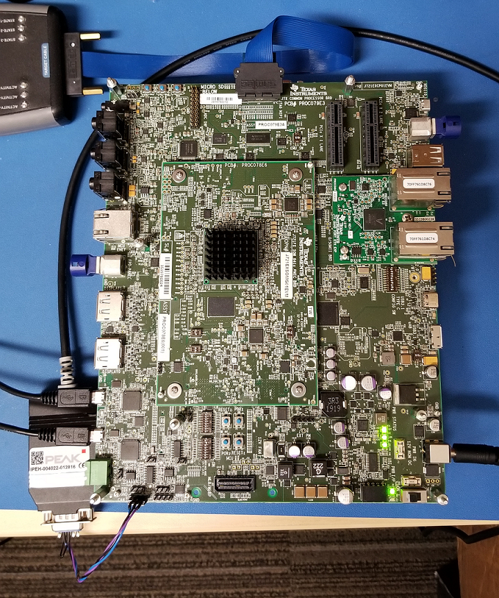
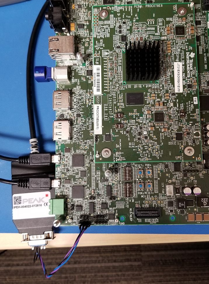
In transmit-only mode, messages can be received if an external CAN utility, like the CANOE tool or the PEAK tool, are connected to the EVM board. However, this demonstration only uses the first instance, MCU_MCAN0. Below are the configuration flags associated with this feature.
Enable TX-only mode (vs. RX-only mode).
Options are "STD_ON" or "STD_OFF".
CAN TX only configuration is present at mcusw/mcuss_demos/boot_app_mcu_rtos/can_resp.h (if using CAN Response task) AND mcuss_demos/boot_app_mcu_rtos/can_profile.h (if using CAN Profile task)
Options are "STD_ON" or "STD_OFF".
CAN loopback configuration is present at mcusw/mcuss_demos/mcal_config/Can_Demo_Cfg/output/generated/soc/$SOC/mcu1_0/include/Can_Cfg.h
Use first instance of CAN peripheral only
Saves boot time by using only the first instance (MCU_MCAN0) of the CAN peripheral configured. Below is the configuration.
Use first instance of CAN peripheral only.
Options are "STD_ON" or "STD_OFF".
CAN configuration is present at mcusw/mcuss_demos/boot_app_mcu_rtos/can_resp.h (if using CAN Response task) AND mcuss_demos/boot_app_mcu_rtos/can_profile.h (if using CAN Profile task)
| For TX Only | Flag Value | Location |
|---|---|---|
| APP_INSTANCE_1_INST_IN_CFG_ONLY | STD_ON | mcuss_demos/boot_app_mcu_rtos/can_resp.h AND mcuss_demos/boot_app_mcu_rtos/can_profile.h |
| CAN_LOOPBACK_ENABLE | STD_OFF | mcuss_demos/mcal_config/Can_Demo_Cfg/output/generated/soc/$SOC/mcu1_0/include/Can_Cfg.h |
| CAN_TX_ONLY_MODE | STD_ON | mcuss_demos/boot_app_mcu_rtos/can_resp.h AND mcuss_demos/boot_app_mcu_rtos/can_profile.h |
| Loopback | Flag Value | Location |
|---|---|---|
| APP_INSTANCE_1_INST_IN_CFG_ONLY | STD_OFF | mcuss_demos/boot_app_mcu_rtos/can_resp.h AND mcuss_demos/boot_app_mcu_rtos/can_profile.h |
| CAN_LOOPBACK_ENABLE | STD_ON | mcuss_demos/mcal_config/Can_Demo_Cfg/output/generated/soc/$SOC/mcu1_0/include/Can_Cfg.h |
| CAN_TX_ONLY_MODE | X | mcuss_demos/boot_app_mcu_rtos/can_resp.h AND mcuss_demos/boot_app_mcu_rtos/can_profile.h |
We need have the following binaries built from Platform Development Kit (PDK):
Apart from the above binaries, we need to build the can_boot_app_mcu_rtos that the SBL copies from OSPI, and does the following:
Go to pdk/packages/ti/build and run the following w/ $board set accordingly:
NOTE: For Early CAN response with the fastest boot time, you can pre-configure the SBL flags before building sbl_boot_perf_cust_img by modifying the CUST_SBL_BOOT_PERF_TEST_FLAGS in the file pdk/packages/ti/boot/sbl/sbl_component.mk. Just search for this line and un-comment it (and comment out similar lines below it), then save and build sbl_boot_perf_cust_img.
Go to mcusw/build and run the following w/ $board and $soc set accordingly:
The output appimage "can_boot_app_mcu_rtos_mcu1_0_release.appimage" will be placed in mcusw/binary/can_boot_app_mcu_rtos/bin/$board directory.
To run the main domain applications on all the main domain cores, flash the following binaries in OSPI memory at the respective offsets (in hex) as given below:
J721E, J721S2, J784S4:
NOTE: {BOARD} and {X} needs to be substituted accordingly.
J7200:
Refer Uniflash Programming Guide to learn how to program the binaries at the respective offset in the flash.
Below is the log for CAN Boot App (J721E) when CAN is configured in loop-back mode, and all main domain cores run some application:
CAN Response App:NOTE : Operating in internal loop-back mode
CAN Response App:Message Id Received 800000c0 Message Length is 64
CAN Response App:Test completed for 0 instance

CAN Response App:NOTE : Operating in internal loop-back mode
CAN Response App:Message Id Received 800000b0 Message Length is 64
CAN Response App:Test completed for 1 instance

C OSPI NOR device ID: 0x5b1a, manufacturer ID: 0xCAN Response App: 8192 bytes used for stack
CAN Response App: 8192 bytes used for stack
CAN Response App:Early CAN completed!!!
Boot App: Started at 347 usec
Boot App: Total Num booted cores = 8
Boot App: Booted Core ID #6 at 294663 usecs
Boot App: Booted Core ID #7 at 294937 usecs
Boot App: Booted Core ID #8 at 311442 usecs
Boot App: Booted Core ID #9 at 311717 usecs
Boot App: Booted Core ID #10 at 312044 usecs
Boot App: Booted Core ID #11 at 312372 usecs
Boot App: Booted Core ID #12 at 312807 usecs
Boot App: Booted Core ID #0 at 319346 usecs

MCU Boot Task started at 345 usecs and finished at 1931335 usecs
| Revision | Date | Author | Description | Status |
|---|---|---|---|---|
| 0.1 | 16 Apr 2019 | Somnath | Initial Version | Approved |
| 0.2 | 8 Aug 2019 | Sunil M S | Updates logs for release 00.09.01 | Approved |
| 0.3 | 30 Jan 2020 | Danny Jochelson | New Version For TIRTOS Boot App | Approved |
| 0.4 | 4 Feb 2020 | Jonathan Bergsagel | Updated for CAN boot app CAN response compile options | Approved |
| 0.5 | 17 Feb 2020 | Sujith S | Re Organized the document | Approved |
| 0.6 | 28 May 2020 | Jonathan Bergsagel | Updated CAN boot app instructions for 7.0 SDK release | Approved |
| 0.7 | 22 Sept 2020 | Danny Jochelson | Updated CAN boot app to include BIST task, Updated Boot Task to show staged image parsing | Approved |
| 0.8 | 4 Nov 2020 | Jonathan Bergsagel | Updated instructions to include J7200 support, and new OSPI flash memory layout for images | Approved |
| 0.9 | 17 Nov 2020 | Jonathan Bergsagel | Removed prior issue on booting Linux. Boot App enables an optimized Linux boot flow | Approved |
 1.8.15