|
MCUSW
|
|
MCUSW
|
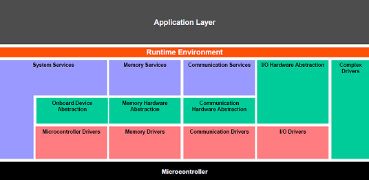
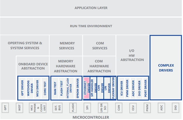
The figure below depicts the AUTOSAR layered architecture as 3 distinct layers, Application, Runtime Environment (RTE) and Basic Software (BSW). The BSW is further divided into 4 layers, Services, Electronic Control Unit Abstraction, MicroController Abstraction (MCAL) and Complex Drivers.
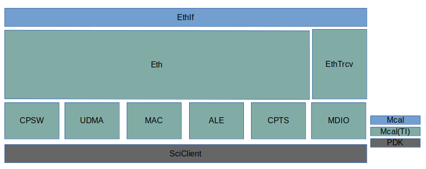
MCAL is the lowest abstraction layer of the Basic Software. It contains software modules that interact with the Microcontroller and its internal peripherals directly. The ETH driver is part of the Communication Drivers module which is also part of the Basic Software. The block diagram below shows the position of the Ethernet driver in the AUTOSAR Architecture.
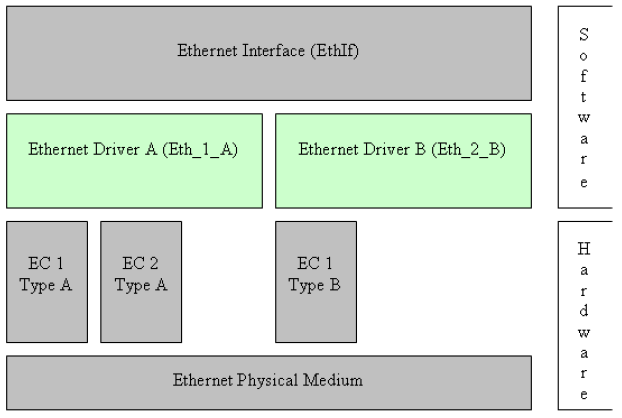
As described in the AUTOSAR Ethernet Driver specification, the Ethernet Driver (Eth) is in charge of providing a uniform, hardware independent interface to the upper layer, the Ethernet Interface (EthIf). Thus, the Ethernet Interface may access the underlying bus system in a uniform manner.
The driver provides bus specific functionality for controller initialization, configuration, data transmission, data reception, statistics gathering, etc. A single Ethernet Driver module supports only one type of controller hardware, but several controllers of the same type. Figure below shows the lower part of the Ethernet stack.
This Ethernet Driver implementation shall support an Ethernet controller based on the two-port Gigabit Ethernet Switch (CPSW) peripheral present in the MCU domain of the TDA4x family of devices.
Refer to the Ethernet Driver and Ethernet Interface specification in References section for more details on Eth operation.
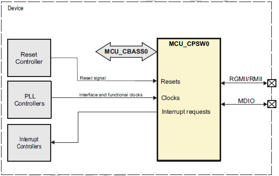
The TDA4x family of devices have an integrated the two-port Gigabit Ethernet Switch (CPSW) into the device MCU domain named MCU_CPSW0. Please refer to figure below for a block diagram of the peripheral.
Port 0 is the internal Communications Port Programming Interface (CPPI) host port. Port 1 is the Ethernet port which supports RGMII and RMII interfaces.
The CPSW peripheral natively supports features like IEEE 1588 Clock Synchronization, Address Lookup Engine (ALE), and Ethernet Statistics. Further information on these and several other features supported by the CPSW subsystem can be found in the device TRM.
| Sl No | Specification | Comment / Link |
|---|---|---|
| 1 | AUTOSAR 4.3.1 | AUTOSAR Specification for Eth Driver Internet Link |
| 2 | AUTOSAR 4.3.1 | Specification of the Ethernet Interface Internet Link |
| 3 | AUTOSAR 4.3.1 BSW | General Specification of Basic Software Modules Internet Link |
| 4 | AUTOSAR 4.3.1 | List of Basic Software Modules, AUTOSAR Release Internet Link |
| 5 | TDA4x TRM | Technical Reference Manual, TDA4X Ethernet module is detailed |
| 6 | BSW General Requirements / Coding guidelines | Intranet Link |
| 7 | Software Product Specification (SPS) | Intranet Link Requirements are derived from [1] |
| 8 | AUTOSAR 4.3.1 | Specification of the Ethernet State Manager Internet Link |
The Eth driver shall implement as per requirements detailed in the Software Product Specification (SPS) [7], Ethernet Driver specification [1] and Basic Software Modules specification [3]. It’s recommended to refer to the Ethernet Driver specification [1] for any clarification.
The Eth driver shall follow coding guidelines listed in the BSW General Requirements and Coding Guidelines document [6].
Below listed are some of the key features that are expected to be supported
| Design ID | DES_ETH_001 |
| Requirements Covered | SWS_Eth_00003, SWS_Eth_00004, SWS_Eth_00006, SWS_Eth_00007, SWS_Eth_00011, SWS_Eth_00026, SWS_Eth_00119, SWS_Eth_00148, SWS_Eth_00218 |
Configuration Requirements
| Design ID | DES_ETH_039 |
| Requirements Covered | SWS_Eth_00005, SWS_Eth_00010, SWS_Eth_00012, SWS_Eth_00013, SWS_Eth_00124, SWS_Eth_00125, SWS_Eth_00126 |

Priority pamareter should be set to 0 when requesting a buffer via Eth_ProvideTxBuffer.FifoIdx parameter should be set to 0 when receiving a buffer via Eth_Receive.EthGetRxStatsApi name is assumed in this implementation.Below listed are assumed to valid for this design/implementation, exceptions and other deviations are listed for each explicitly. Care should be taken to ensure these assumptions are addressed.
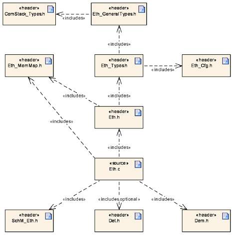
The Ethernet driver relies on the TI Chip Support Library (CSL) as well as the PDK UDMA driver. CSL provides register addresses, definitions and helper functions for several modules and sub-modules of the device, including CPSW, CPGMAC, etc. The UDMA driver provides an interface to configure and manage DMA transfers which facilitates and hides the complexity of the programming of the UDMA, Ring Accelerator, PSI-L and other DMA related modules.
The Ethernet driver implementation shall be divided into a number of files that mirror the different functionality of the CPSW peripheral. The block diagram below shows the driver, its subcomponent as well as the CSL and UDMA dependency.
The data flow model of the AUTOSAR Ethernet driver requires that buffers are passed one by one to/from the upper layers. Additionally, there are a number of memory copy operations that need to take place in the lifecycle of packet buffer across the upper layers (i.e. UDP, RTP, etc). This Ethernet driver design aims to being able to scale the driver implementation for higher data throughput
The driver maintains the following three states: UNINIT, INIT and ACTIVE. Please refer to the sequence diagrams shown in the Specification of Ethernet State Manager [8], for further details on the interactions and transitions between those states.
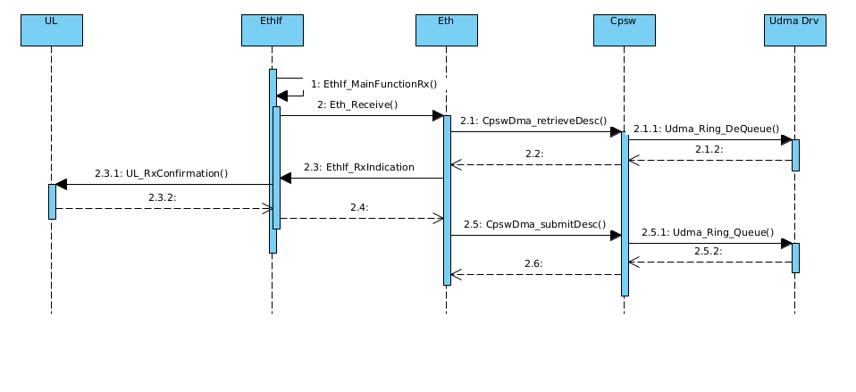
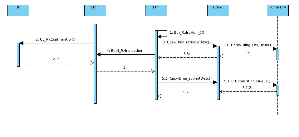
The following sequence diagrams the data flow interactions between the EthIf, Eth and the proposed design. These sequence diagrams extended from the diagrams of the Ethernet Interface specification document [2].
The sequence diagrams below list control / data flow for transmission in polling and interrupt methods.
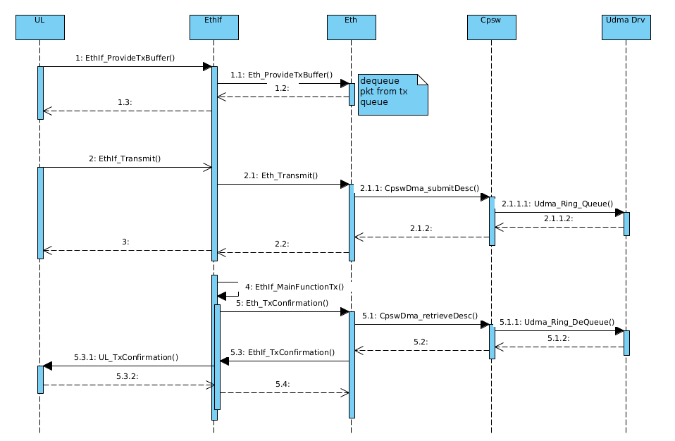
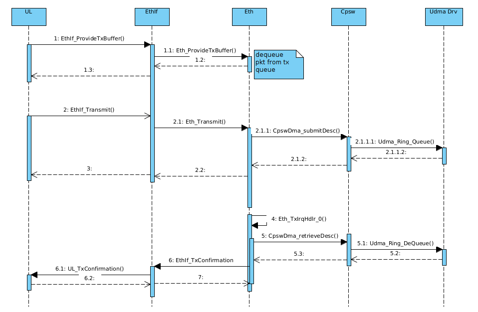
The sequence diagrams below list control / data flow for transmission in polling and interrupt methods.
The directory structure is as depicted in figures below, the source files can be categorized under “Driver Implementation” and “Example Application”
Driver Implemented by
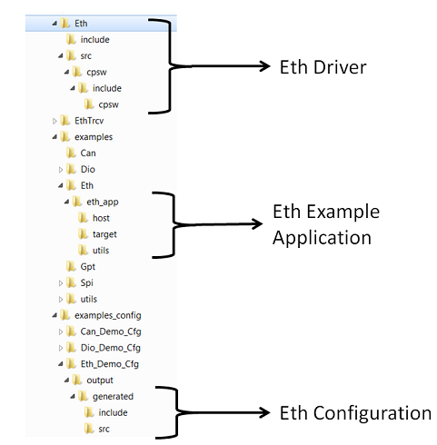
Example Application
| Design ID | DES_ETH_002 |
| Requirements Covered | MCAL-2132 |
The Ethernet Driver supports two data transfer related interrupts, one for transmission and another for reception. These interrupts are generated when the underlying completion queue rings (CQ Rings) associated with TX and RX get a descriptor from CPSW. For TX, this event signalizes that a previous transmission has completed and its descriptor is free to be reused. For RX, this event signalizes the arrival of new packet.
The Eth_RxIrqHdlr_0() interrupt service routine shall clear the interrupt and read the frames of all received buffers. This driver design takes into consideration the ability to receive several frames from the DMA engine. The driver shall call the Ethernet Interface callback function EthIf_RxIndication() on each received frame.
The Eth_TxIrqHdlr_0() interrupt service routine shall clear the interrupt and check all filled transmit buffers for successful transmission. The driver shall call the Ethernet Interface callback function EthIf_TxConfirmation() for each transmit frame, if requested.
The statistics interrupt is generated when any statistics value is greater than or equal to 0x80000000. The service routine for this interrupt shall clear the interrupt and update the statistics counter(s) accordingly. The intention of this event is to avoid overflow in the 32-bit wide statistics counter values in hardware.
The AUTOSAR Eth Driver Specification details mandatory parameters that shall be configurable via the configurator. Please refer section 10 of the Ethernet driver specification listed in References section.
| Design ID | DES_ETH_024 |
| Requirements Covered | ECUC_Eth_00001, ECUC_Eth_00002, ECUC_Eth_00003, ECUC_Eth_00004, ECUC_Eth_00006, ECUC_Eth_00007, ECUC_Eth_00010, ECUC_Eth_00011, ECUC_Eth_00012, ECUC_Eth_00015, ECUC_Eth_00016, ECUC_Eth_00017, ECUC_Eth_00018, ECUC_Eth_00019, ECUC_Eth_00020, ECUC_Eth_00021, ECUC_Eth_00022, ECUC_Eth_00023, ECUC_Eth_00024, ECUC_Eth_00025, ECUC_Eth_00026, ECUC_Eth_00027, ECUC_Eth_00028, ECUC_Eth_00029, ECUC_Eth_00030, ECUC_Eth_00031, ECUC_Eth_00032, ECUC_Eth_00033, ECUC_Eth_00034, ECUC_Eth_00035, ECUC_Eth_00036, ECUC_Eth_00037, ECUC_Eth_00038, ECUC_Eth_00039, ECUC_Eth_00040, ECUC_Eth_00041, ECUC_Eth_00042, ECUC_Eth_00043, ECUC_Eth_00044, ECUC_Eth_00045, ECUC_Eth_00046, ECUC_Eth_00047, ECUC_Eth_00048, ECUC_Eth_00049, ECUC_Eth_00050, ECUC_Eth_00051, ECUC_Eth_00052, ECUC_Eth_00053, ECUC_Eth_00054, ECUC_Eth_00055, ECUC_Eth_00056, ECUC_Eth_00057, ECUC_Eth_00058, ECUC_Eth_00059, ECUC_Eth_00060, ECUC_Eth_00061, ECUC_Eth_00062, ECUC_Eth_00063 |
Following lists this design’s specific configurable parameters
| Parameter | Usage comment |
|---|---|
| EthEnableCacheOps | This shall allows integrators configure the Eth driver to perform cache operations. |
| EthCacheWbOps | Once Eth driver is enabled for cache operations, a pointer to a function that is expected to perform cache write-back operation |
| EthCacheWbInvOps | Once Eth driver is enabled for cache operations, a pointer to a function that is expected to perform cache write-back-and-invalidate operation |
| EthCacheInvalidateOps | Once Eth driver is enabled for cache operations, a pointer to a function that is expected to perform cache invalidate operation |
| EthMdioClkFreq | Allows integrators to specify the MDIO clock frequency. Device TRM details the frequency based on the PLL configurations |
| EthMdioBusFreq | Allows integrators to specify the MDIO BUS frequency (MDCLK). Device TRM details the frequency based on the PLL configurations |
| EthConnType | Allows integrators to specify the MII connection type |
| EthEnableLoopBack | Allows integrators to enable or disable loopback mode of operation. Expected to be used for debug |
| EthUseDefaultMacAddr | Allows integrators to use MAC address that is present in ROM |
| EthDefaultOSCounterId | This shall allow integrators to specify the OS counter instance to be used in OS API GetCounterValue () The driver shall implement timed-wait for all waits (e.g. waiting for reset to complete). This timed wait shall use OS API GetCounterValue () |
| EthTimeoutDuration | Allow integrators to configure the time duration for which Eth-Busy should wait. Mainly needed for PHY register accesses |
| EthDmaTxChIntrNum | Allows integrators to specify the UDMA transmit interrupt number |
| EthDmaRxChIntrNum | Allows integrators to specify the UDMA receive interrupt number |
| EthDmaRxChStartNum | Allows integrators to specify the UDMA Rx channel start number |
| EthDmaTxChStartNum | Allows integrators to specify the UDMA Tx channel start number |
| EthDmaRingStartNum | Allows integrators to specify the UDMA Ring start number |
| EthDmaFlowStartNum | Allows integrators to specify the UDMA Flow start number |
| EthDmaGlobalStartNum | Allows integrators to specify the UDMA global event number |
| EthDmaVirtualIntrStartNum | Allows integrators to specify the UDMA virtual interrupt number |
The ETH driver shall provide driver status for debugging. The states ETH_STATE_UNINIT and ETH_STATE_INIT can be probed.
| Design ID | DES_ETH_035 |
| Requirements Covered | SWS_Eth_00159 |
Errors are classified in two categories, development error and runtime / production error.
| Design ID | DES_ETH_034 |
| Requirements Covered | SWS_Eth_00008, SWS_Eth_00120 |
Development errors are reported to the DET using the service Det_ReportError() if development error detection and reporting are enabled. The reported ETH module ID is 088 4.
The following table presents the service IDs and the related services:
| Service ID (HEX) | Service Name |
| 0x01 | Eth_Init |
| 0x03 | Eth_SetControllerMode |
| 0x04 | Eth_GetControllerMode |
| 0x05 | Eth_WriteMii |
| 0x06 | Eth_ReadMii |
| 0x08 | Eth_GetPhysAddr |
| 0x09 | Eth_ProvideTxBuffer |
| 0xA | Eth_Transmit |
| 0x0B | Eth_Receive |
| 0x0C | Eth_TxConfirmation |
| 0xD | Eth_GetVersionInfo |
| 0x12 | Eth_UpdatePhysAddrFilter |
| 0x13 | Eth_SetPhysAddr |
| 0x14 | Eth_GetCounterValues |
| 0x15 | Eth_GetRxStats |
| 0x16 | Eth_GetCurrentTime |
| 0x17 | Eth_EnableEgressTimeStamp |
| 0x18 | Eth_GetEgressTimeStamp |
| 0x19 | Eth_GetIngressTimeStamp |
| 0x1C | Eth_GetTxStats |
| 0x1D | Eth_GetTxErrorCounterValue |
| 0x20 | Eth_MainFunction |
The detection of development errors is configurable (ON / OFF) at pre-compile time. The switch EthDevErrorDetect will activate or deactivate the detection of all development errors.
All detected development errors are reported to Det_ReportError service of the Development Error Tracer (DET).
| Design ID | DES_ETH_003 |
| Requirements Covered | SWS_Eth_00016, SWS_Eth_00043, SWS_Eth_00044, SWS_Eth_00048, SWS_Eth_00049, SWS_Eth_00050, SWS_Eth_00054, SWS_Eth_00055, SWS_Eth_00056, SWS_Eth_00140, SWS_Eth_00141, SWS_Eth_00142, SWS_Eth_00164, SWS_Eth_00165, SWS_Eth_00166, SWS_Eth_00060, SWS_Eth_00061, SWS_Eth_00066, SWS_Eth_00067, SWS_Eth_00068, SWS_Eth_00228, SWS_Eth_00229, SWS_Eth_00230, SWS_Eth_00235, SWS_Eth_00236, SWS_Eth_00237, SWS_Eth_00182, SWS_Eth_00183, SWS_Eth_00184, SWS_Eth_00187, SWS_Eth_00188, SWS_Eth_00191, SWS_Eth_00192, SWS_Eth_00193, SWS_Eth_00196, SWS_Eth_00197, SWS_Eth_00198, SWS_Eth_00081, SWS_Eth_00082, SWS_Eth_00083, SWS_Eth_00084, SWS_Eth_00085, SWS_Eth_00090, SWS_Eth_00091, SWS_Eth_00092, SWS_Eth_00093, SWS_Eth_00129, SWS_Eth_00097, SWS_Eth_00098, SWS_Eth_00132, SWS_Eth_00103, SWS_Eth_00104, SWS_Eth_00134, SWS_Eth_00136 |
The Eth driver shall be capable of reporting the following production errors using the Dem_ReportErrorStatus() interface from the Diagnostics Event Manager (DEM), as specified by the AUTOSAR Ethernet Driver specification.
| Type of Error | Related Error code | Value (Hex) |
| Invalid controller index | ETH_E_INV_CTRL_IDX | 0x01 |
| Eth module or controller was not initialized | ETH_E_NOT_INITIALIZED | 0x02 |
| Invalid pointer in the parameter list | ETH_E_PARAM_POINTER | 0x03 |
| Invalid parameter | ETH_E_INV_PARAM | 0x04 |
| Initialization failure | ETH_E_INIT_FAILED | 0x05 |
| Invalid mode | ETH_E_INV_MODE | 0x06 |
The CPSW module is capable of recording and reporting statistics related to different types of traffic events. A subset of those statistics shall be mapped to the error types required in the AUTOSAR Ethernet driver specification as follows:
| Design ID | DES_ETH_032 |
| Requirements Covered | SWS_Eth_00173, SWS_Eth_00174, SWS_Eth_00219, SWS_Eth_00220, SWS_Eth_00221, SWS_Eth_00222, SWS_Eth_00223, SWS_Eth_00224, SWS_Eth_00225 |
| Design ID | DES_ETH_036 |
| Requirements Covered | MCAL-2129 |
| Design ID | DES_ETH_037 |
| Requirements Covered | MCAL-2128 |
For the standard API's please refer 8.3 of 1. Sections below highlight other design considerations for the implementation.
Refer section 8.3.1 of the Ethernet Driver specification [1].
| Design ID | DES_ETH_005 |
| Requirements Covered | SWS_Eth_00027, SWS_Eth_00028, SWS_Eth_00029, SWS_Eth_00031, SWS_Eth_00034, SWS_Eth_00039 |
Refer section 8.3.2 of the Ethernet Driver specification [1].
| Design ID | DES_ETH_007 |
| Requirements Covered | SWS_Eth_00041, SWS_Eth_00042, SWS_Eth_00043, SWS_Eth_00044, SWS_Eth_00045, SWS_Eth_00168 |
Refer section 8.3.3 of the Ethernet Driver specification [1].
| Design ID | DES_ETH_008 |
| Requirements Covered | SWS_Eth_00046, SWS_Eth_00047, SWS_Eth_00048, SWS_Eth_00049, SWS_Eth_00050, SWS_Eth_00051 |
Refer section 8.3.4 of the Ethernet Driver specification [1].
| Design ID | DES_ETH_009 |
| Requirements Covered | SWS_Eth_00052, SWS_Eth_00053, SWS_Eth_00054, SWS_Eth_00055, SWS_Eth_00056, SWS_Eth_00057 |
Refer section 8.3.5 of the Ethernet Driver specification [1].
| Design ID | DES_ETH_019 |
| Requirements Covered | SWS_Eth_00139, SWS_Eth_00140, SWS_Eth_00141, SWS_Eth_00142, SWS_Eth_00143, SWS_Eth_00151 |
Refer section 8.3.6 of the Ethernet Driver specification [1].
| Design ID | DES_ETH_020 |
| Requirements Covered | SWS_Eth_00144, SWS_Eth_00146, SWS_Eth_00147, SWS_Eth_00150, SWS_Eth_00152, SWS_Eth_00164, SWS_Eth_00165, SWS_Eth_00166, SWS_Eth_00167, SWS_Eth_00245, SWS_Eth_00246 |
Refer section 8.3.7 of the Ethernet Driver specification [1].
| Design ID | DES_ETH_010 |
| Requirements Covered | SWS_Eth_00058, SWS_Eth_00059, SWS_Eth_00060, SWS_Eth_00061, SWS_Eth_00062, SWS_Eth_00063, SWS_Eth_00241 |
Refer section 8.3.8 of the Ethernet Driver specification [1].
| Design ID | DES_ETH_011 |
| Requirements Covered | SWS_Eth_00064, SWS_Eth_00065, SWS_Eth_00066, SWS_Eth_00067, SWS_Eth_00068, SWS_Eth_00069, SWS_Eth_00070, SWS_Eth_00242 |
Refer section 8.3.9 of the Ethernet Driver specification [1].
| Design ID | DES_ETH_022 |
| Requirements Covered | SWS_Eth_00226, SWS_Eth_00227, SWS_Eth_00228, SWS_Eth_00229, SWS_Eth_00230, SWS_Eth_00231, SWS_Eth_00232 |
Refer section 8.3.10 of the Ethernet Driver specification [1].
| Design ID | DES_ETH_023 |
| Requirements Covered | SWS_Eth_00233, SWS_Eth_00234, SWS_Eth_00235, SWS_Eth_00236, SWS_Eth_00237, SWS_Eth_00238 |
Refer section 8.3.11 of the Ethernet Driver specification [1].
| Design ID | DES_ETH_040 |
| Requirements Covered | SWS_Eth_00248, SWS_Eth_00249, SWS_Eth_00250, SWS_Eth_00251 |
Refer section 8.3.12 of the Ethernet Driver specification [1].
| Design ID | DES_ETH_041 |
| Requirements Covered | SWS_Eth_91006, SWS_Eth_00252, SWS_Eth_00253, SWS_Eth_00254, SWS_Eth_00255 |
Refer section 8.3.13 of the Ethernet Driver specification [1].
| Design ID | DES_ETH_026 |
| Requirements Covered | SWS_Eth_00181, SWS_Eth_00182, SWS_Eth_00183, SWS_Eth_00184, SWS_Eth_00185, SWS_Eth_00210 |
Refer section 8.3.14 of the Ethernet Driver specification [1].
| Design ID | DES_ETH_027 |
| Requirements Covered | SWS_Eth_00186, SWS_Eth_00187, SWS_Eth_00188, SWS_Eth_00189, SWS_Eth_00211 |
Refer section 8.3.15 of the Ethernet Driver specification [1].
| Design ID | DES_ETH_028 |
| Requirements Covered | SWS_Eth_00190, SWS_Eth_00191, SWS_Eth_00192, SWS_Eth_00193, SWS_Eth_00194, SWS_Eth_00212 |
Refer section 8.3.16 of the Ethernet Driver specification [1].
| Design ID | DES_ETH_029 |
| Requirements Covered | SWS_Eth_00195, SWS_Eth_00196, SWS_Eth_00197, SWS_Eth_00198, SWS_Eth_00199, SWS_Eth_00213 |
Refer section 8.3.17 of the Ethernet Driver specification [1].
| Design ID | DES_ETH_012 |
| Requirements Covered | SWS_Eth_00077, SWS_Eth_00078, SWS_Eth_00079, SWS_Eth_00080, SWS_Eth_00081, SWS_Eth_00082, SWS_Eth_00083, SWS_Eth_00084, SWS_Eth_00085, SWS_Eth_00086, SWS_Eth_00137 |
Refer section 8.3.18 of the Ethernet Driver specification [1].
| Design ID | DES_ETH_013 |
| Requirements Covered | SWS_Eth_00087, SWS_Eth_00088, SWS_Eth_00089, SWS_Eth_00090, SWS_Eth_00091, SWS_Eth_00092, SWS_Eth_00093, SWS_Eth_00094, SWS_Eth_00129, SWS_Eth_00138 |
Refer section 8.3.19 of the Ethernet Driver specification [1].
| Design ID | DES_ETH_014 |
| Requirements Covered | SWS_Eth_00095, SWS_Eth_00096, SWS_Eth_00097, SWS_Eth_00098, SWS_Eth_00099, SWS_Eth_00132, SWS_Eth_00153 |
Refer section 8.3.20 of the Ethernet Driver specification [1].
| Design ID | DES_ETH_015 |
| Requirements Covered | SWS_Eth_00100, SWS_Eth_00101, SWS_Eth_00102, SWS_Eth_00103, SWS_Eth_00104, SWS_Eth_00105, SWS_Eth_00134 |
Refer section 8.3.21 of the Ethernet Driver specification [1].
| Design ID | DES_ETH_016 |
| Requirements Covered | SWS_Eth_00106, SWS_Eth_00136 |
Refer section 8.5.1 of the Ethernet Driver specification [1].
| Design ID | DES_ETH_031 |
| Requirements Covered | SWS_Eth_00169, SWS_Eth_00171, SWS_Eth_00172, SWS_Eth_00240 |
The following Ethernet Interface (EthIf) callbacks are called upon transmission or reception events.
EthIf_TxConfirmation is called by the driver when notification has been enabled in Eth_Transmit().EthIf_RxIndication is called by the driver upon successful reception.| Design ID | DES_ETH_042 |
| Requirements Covered | SWS_Eth_00243, SWS_Eth_00256, SWS_Eth_00244 |
Refer to section 7.1.2 of the Ethernet Driver specification [1] for further information.
The following Ethernet Switch (EthSwt) callbacks are to be called to inform the Ethernet Switch driver about special treatment required for switch management purposes.
| Design ID | DES_ETH_043 |
| Requirements Covered | SWS_Eth_00247 |
Refer to section 7.1.2 of the Ethernet Driver specification [1] for further information.
This feature is not supported in this release. Please refer to Features Not Supported / NON Compliance section for further information.
The following types are required as per AUTOSAR Ethernet Driver specification, 8.2 of the Ethernet Driver specification [1].
| Design ID | DES_ETH_033 |
| Requirements Covered | SWS_Eth_00156, SWS_Eth_00158, SWS_Eth_00159, SWS_Eth_00160, SWS_Eth_00161, SWS_Eth_00162, SWS_Eth_00163, SWS_Eth_00175, SWS_Eth_00177, SWS_Eth_00178, SWS_Eth_00179, SWS_Eth_00180, SWS_Eth_91001, SWS_Eth_91002, SWS_Eth_91003, SWS_Eth_91004 |
This design expects that implementation will require to use following global variables.
| Variable | Type | Description | Default Value |
|---|---|---|---|
| gEthDrvStatus | Eth_StateType | ETH driver status | ETH_STATE_UNINIT |
| gEthDrvObj | Eth_DriverObj | ETH driver object | - |
| gEthTxBufMem | uint8 | TX packet memory pool | - |
| gEthRxBufMem | uint8 | RX packet memory pool | - |
| gEthTxFqRingMem | uint8 | TX free ring memory | - |
| gEthTxCqRingMem | uint8 | TX completion ring memory | - |
| gEthTxTdCqRingMem | uint8 | TX teardown completion ring memory | - |
| gEthRxFqRingMem | uint8 | RX free ring memory | - |
| gEthRxCqRingMem | uint8 | RX completion ring memory | - |
| gEthRxTdCqRingMem | uint8 | RX teardown completion ring memory | - |
| gEthCpswTxPkt | uint8 | TX UDMA Host Packet Descriptor (HPD) memory | - |
| gEthCpswRxPkt | uint8 | RX UDMA Host Packet Descriptor | - |
| cpswCfg | Cpsw_Config | CPSW initialization structure | ALE enabled in VLAN aware mode, all ports in forwarding mode. UDMA TX and RX interrupts disabled. MAC port with TX & RX flow control enabled, error and control frames passing to host enabled |
Host port with CRC removal, short frame padding
Sections below list some of the important design decisions and rational behind those decision.
Traffic throughput can be limited by the underlying mechanism used to pass packets to the Ethernet hardware (CPSW). Unfortunately, the transfer related APIs of the AUTOSAR Ethernet Driver impose a significant constraint on the maximum throughput by processing packets one by one. However, the driver implementation can be done in a way that facilitates future throughput related improvements and customizations.
The ability to achieve higher throughput without significant driver complexity increase.
The capability of scaling the driver for higher Ethernet throughput is a strong argument in favor of the alternative 2 (Queue of Packets). No major overhead is foreseen by using a queue instead of an array of packets. While the driver complexity increases, it’s not significant enough to affect the decision.
The number of data buffers in one Ethernet packet is often a configurable parameter in driver implementations. At this point, the AUTOSAR specification doesn’t require that the driver implementation supports multiple buffers per packet.
Buffers per packet configurability without significant driver complexity increase.
Adding the support for flexible number of buffers per packet in the Ethernet driver is localized changes. Consequently it makes more sense to add this feature when the Ethernet specification mandates it. Recommended to implement option 1 (one buffer per packet).
The sections below identify some of the aspects of design that would require emphasis during testing of this design implementation
| Revision | Date | Author | Description | Status |
|---|---|---|---|---|
| 0.1 | 28 Jun 2018 | Misael Lopez | First version | Approved |
| 0.2 | 04 Oct 2018 | Sujith S | Format change and re-order | Approved |
| 0.3 | 29 May 2020 | Misael Lopez | Updated for AUTOSAR 4.3.1 | Approved |
| 0.4 | 09 Dec 2022 | Quan Tran | Updated for lastest driver implemation | NA |
 1.8.15