Getting Started
Hardware setup
TI’s TDA4VM SoC houses dual core A72, high performance vision accelerators, video codec accelerators, latest C71x and C66x DSP, high bandwidth realtime IPs for capture and display, GPU, dedicated safety island and security accelerators. The SoC is power optimized to provide best in class performance for perception, sensor fusion, localization and path planning tasks in robotics, industrial and automotive applications.
For more details visit https://www.ti.com/product/TDA4VM
TDA4VM SK
TDA4VM Edge AI Starter Kit (SK) is a low cost, small form factor board designed to bring smart cameras, robots and intelligent machines to life. For more information related to the board, full list of peripherals supported, pin settings for boot modes and more visit TDA4VM-EdgeAI-SK.
To run the demos on TDA4VM SK you will require,
TDA4VM Edge AI Starter Kit
USB camera (Any V4L2 compliant 1MP/2MP camera, Eg. Logitech C270/C920/C922)
Full HD eDP/HDMI display
Minimum 16GB high performance SD card
100Base-T Ethernet cable connected to internet
UART cable
External Power Supply or Power Accessory Requirements
Nominal Output Voltage: 5-20VDC
Maximum Output Current: 5000 mA
Refer to TDA4VM-EdgeAI-SK for more details.
Connect the components to the SK as shown in the image.
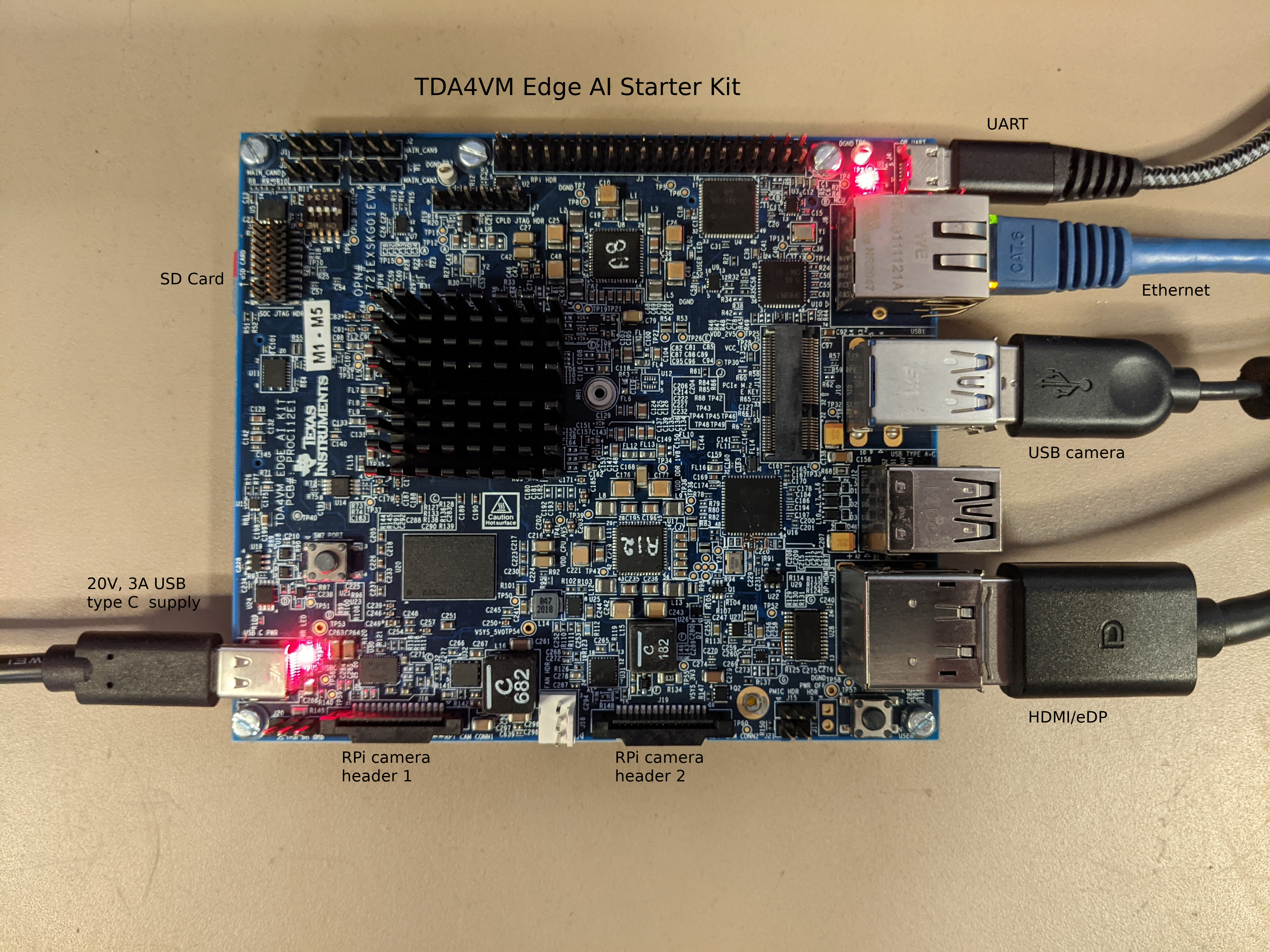
Fig. 4 TDA4VM Starter Kit for Edge AI connections
Set the boot pins to SD boot mode as shown in the following image.
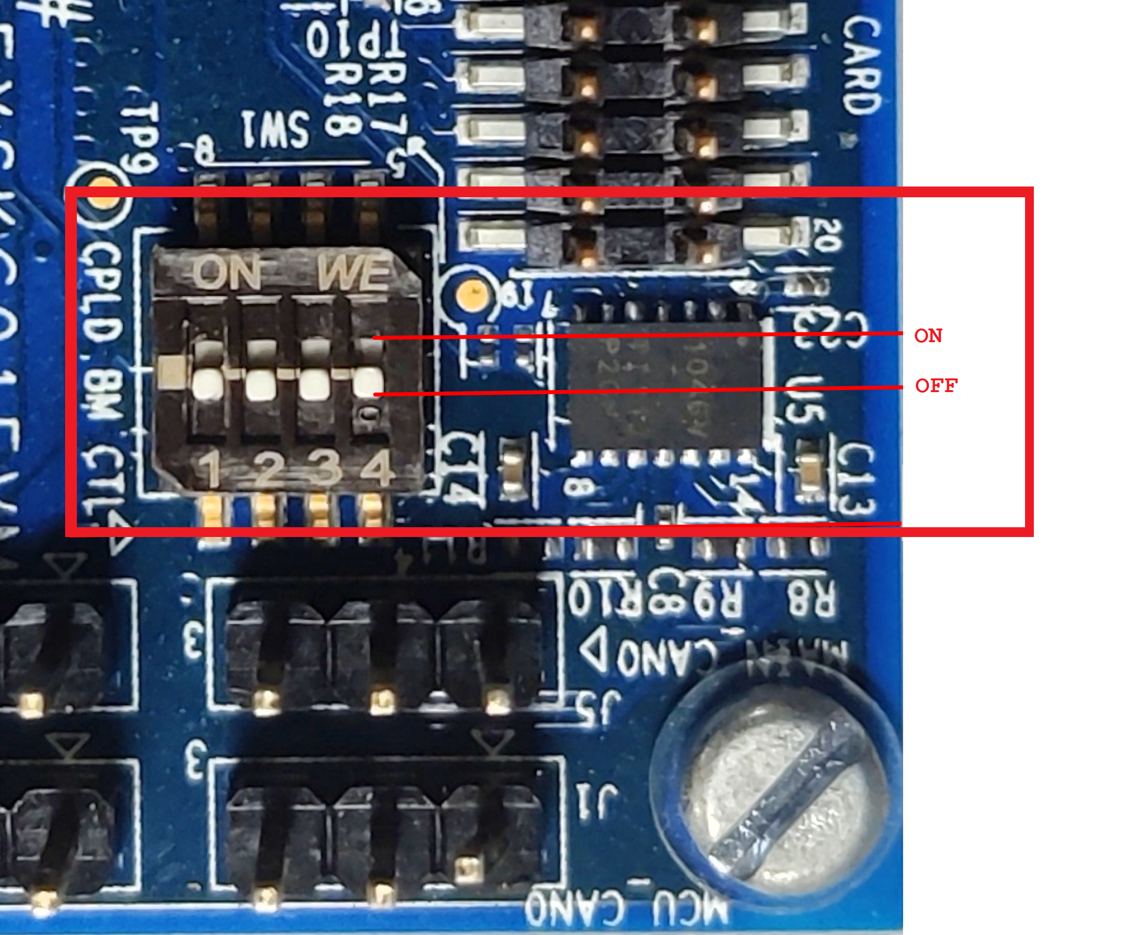
Fig. 5 TDA4VM Starter Kit for Edge AI boot pins
USB Camera
UVC (USB video class) compliant USB cameras are supported on the starter kit. The driver for the same is enabled in SDK. The SDK has been tested with C270/C920/C922 versions of Logitech USB cameras. Please refer to Getting Error when trying to capture from multiple USB cameras simultaneously to stream from multiple USB cameras simultaneously.
OV5640 YUV sensor
OV5640 CSI camera module is a 2MP sensor with built-in ISP which can transmit raw YUYV frames over CSI lanes. This camera module can be ordered from https://www.leopardimaging.com/product/cmos-sensor-modules/mipi-camera-modules/li-am65x-csi2. The camera can be connected to the bottom side of the Edge AI SK board as shown below. The OV5640 camera module requires an additional power supply with following requirements
Output Voltage: 5 VDC
Output Current: 2.0 A
For added flexibility you can order a Samtec extender cable from here, https://www.samtec.com/products/hqcd
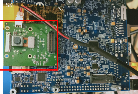
Fig. 6 OV5640 CSI based YUV sensor connection with TDA4VM Starter Kit for Edge AI
Note
By default OV5640 is disabled for TDA4VM SK. After connecting the
camera you can enable it by specifying the dtb overlay file in
/run/media/mmcblk0p1/uenv.txt as below,
name_overlays=k3-j721e-edgeai-apps.dtbo k3-j721e-sk-csi2-ov5640.dtbo
Reboot the board after editing and saving the file.
RPiV2(IMX219) Raw sensor
RPiV2 camera module is supported by TDA4VM SK. It is a 8MP sensor with no ISP, which can transmit raw SRGGB8 frames over CSI lanes at 1080p 60 fps. This camera module can be ordered from https://www.amazon.com/Raspberry-Pi-Camera-Module-Megapixel/dp/B01ER2SKFS The camera can be connected to any of the 2 RPi headers on Edge AI SK board as shown below
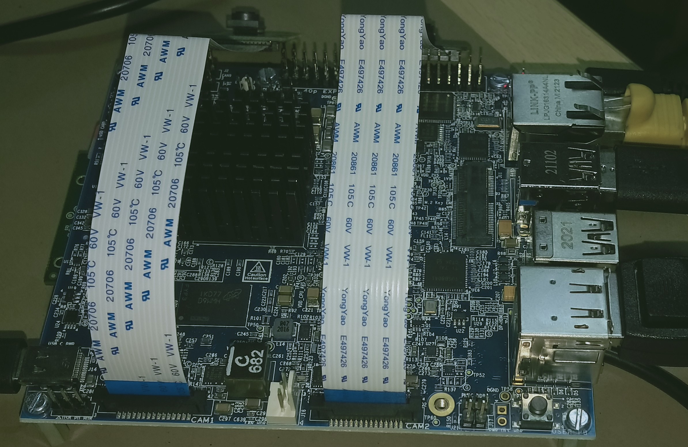
Fig. 7 IMX219 CSI sensor connection with TDA4VM Starter Kit for Edge AI
Note that the headers have to be lifted up to connect the cameras
Note
By default IMX219 is disabled. After connecting the camera you can enable it
by specifying the dtb overlay file in
/run/media/mmcblk0p1/uenv.txt as below,
name_overlays=k3-j721e-edgeai-apps.dtbo k3-j721e-sk-rpi-cam-imx219.dtbo
Reboot the board after editing and saving the file.
Two RPi cameras can be connected to 2 headers for multi camera usecases
Please refer Camera sources (v4l2) to know how to list all the cameras connected and select which one to use for the demo.
By default imx219 will be configured to capture at 8 bit, but it also supports 10 bit capture in 16 bit container. To use it in 10 bit mode, below steps are required:
Modify the
/opt/edge_ai_apps/scripts/setup_cameras.shto set the format to 10 bit like belowCSI_CAM_0_FMT='[fmt:SRGGB8_1X10/1920x1080]' CSI_CAM_1_FMT='[fmt:SRGGB8_1X10/1920x1080]'
Change the imaging binaries to use 10 bit versions
mv /opt/imaging/imx219/dcc_2a.bin /opt/imaging/imx219/dcc_2a_8b.bin
mv /opt/imaging/imx219/dcc_viss.bin /opt/imaging/imx219/dcc_viss_8b.bin
mv /opt/imaging/imx219/dcc_2a_10b.bin /opt/imaging/imx219/dcc_2a.bin
mv /opt/imaging/imx219/dcc_viss_10b.bin /opt/imaging/imx219/dcc_viss.bin
Set the input format in the
/opt/edge_ai_apps/configs/rpiV2_cam_example.yamlasrggb10
IMX390 Raw sensor
IMX390 camera is supported by TDA4VM SK. It is a 8MP sensor with no ISP and fisheye lens, which can transmit raw SRGGB12 frames over CSI lanes at 1080p 60 fps.
Note
By default IMX390 is disabled. After connecting the camera you can enable it
by specifying the dtb overlay file in
/run/media/mmcblk0p1/uenv.txt as below,
name_overlays=k3-j721e-edgeai-apps.dtbo k3-j721e-sk-fpdlink-fusion.dtbo k3-j721e-cpb-fpdlink-imx390-<version>-<x>-<y>.dtbo
Variant of the camera: <version> = {cm, rcm}
CSI lane the camera is connected to: <x> = {0, 1}
Position on fusion board: <y> = {0, 1, 2, 3}
Multiple cameras can be connected, with one dtbo entry for each camera. Reboot the board after editing and saving the file.
8 IMX390 cameras can be connected to through the fusion board for multi camera usecases
Please refer Camera sources (v4l2) to know how to list all the cameras connected and select which one to use for the demo.
Software setup
Preparing SD card image
Download the ti-processor-sdk-linux-sk-tda4vm-etcher-image.zip image and flash it to SD card using Balena etcher tool available at:
Note
We have tested with Balena Etcher version 1.7.0 which can be found here, https://github.com/balena-io/etcher/releases/tag/v1.7.0
There seem to be a known-issue with latest 1.7.2 version of Balena Etcher https://forums.balena.io/t/etcher-error-message-cannot-read-property-message-of-null/350471
The tool can be installed either on Windows/Linux. Just download the etcher image and follow the instructions to prepare the SD card.
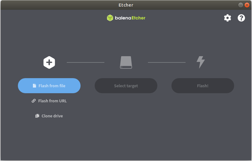
Fig. 8 Balena Etcher tool to flash SD card with Processor SDK Linux for Edge AI
The etcher image is created for 16 GB SD cards, if you are using larger SD card, it is possible to expand the root filesystem to use the full SD card capacity using below steps
#find the SD card device entry using lsblk (Eg: /dev/sdc)
#use the following commands to expand the filesystem
#Make sure you have write permission to SD card or run the commands as root

#Unmount the BOOT and rootfs partition before using parted tool
umount /dev/sdX1
umount /dev/sdX2

#Use parted tool to resize the rootfs partition to use
#the entire remaining space on the SD card
#You might require sudo permissions to execute these steps
parted -s /dev/sdX resizepart 2 '100%'
e2fsck -f /dev/sdX2
resize2fs /dev/sdX2

#replace /dev/sdX in above commands with SD card device entry
Power ON and Boot
Ensure that the power supply is disconnected before inserting the SD card. Once the SD card is firmly inserted in its slot and the board is powered ON, the board will take less than 20sec to boot and display a wallpaper as shown in the image below.
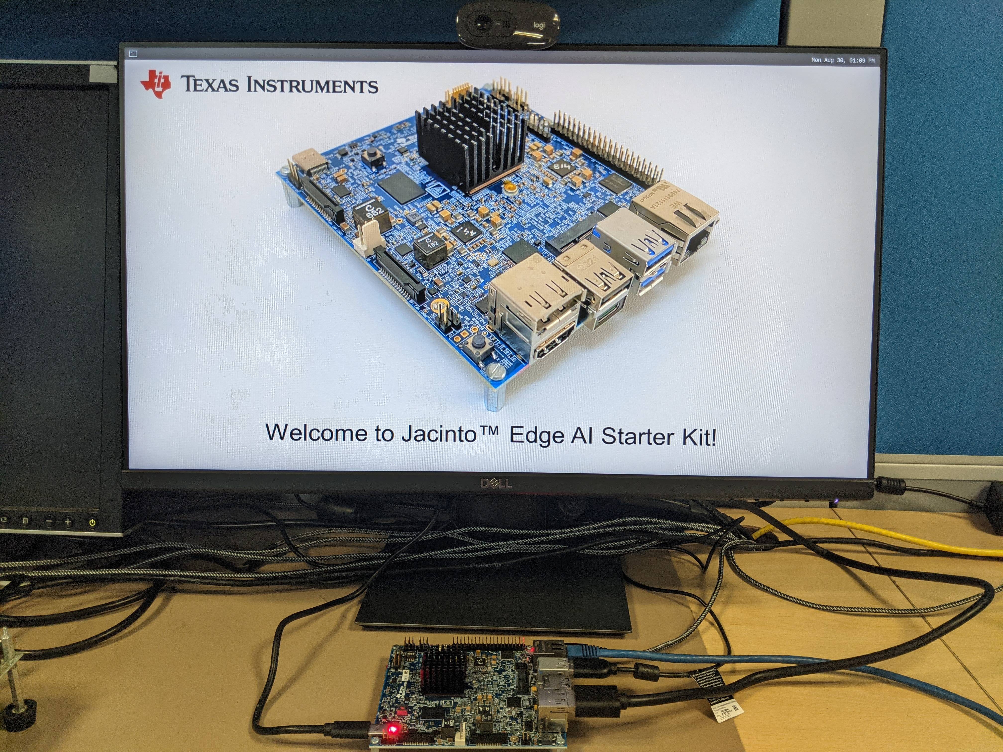
Fig. 9 TDA4VM Starter Kit wallpaper upon boot
You can also view the boot log by connecting the UART cable to your PC and use a serial port communications program.
For Linux OS minicom works well. Please refer to the below documentation on ‘minicom’ for more details.
https://help.ubuntu.com/community/Minicom
When starting minicom, turn on the colors options like below:
sudo minicom -D /dev/ttyUSB2 -c on
For Windows OS Tera Term works well. Please refer to the below documentation on ‘TeraTerm’ for more details
https://learn.sparkfun.com/tutorials/terminal-basics/tera-term-windows
Note
Baud rate should be configured to 115200 bps in serial port communication program. You may not see any log in the UART console if you connect to it after the booting is complete or login prompt may get lost in between boot logs, press ENTER to get login prompt
As part of the linux systemd /opt/edge_ai_apps/init_script.sh is executed
which does the below,
This kills weston compositor which holds the display pipe. This step will make the wallpaper showing on the display disappear and come back
The display pipe can now be used by ‘kmssink’ GStreamer element while running the demo applications.
The script can also be used to setup proxies if connected behind a firewall.
Once Linux boots login as root user with no password.
Connect remotely
If you don’t prefer the UART console, you can also access the device with the IP address that is shown on the display.
With the IP address one can ssh directly to the board, view the contents and run the demos.
For best experience we recommend using VSCode which can be downloaded from here.
https://code.visualstudio.com/download
You also require the “Remote development extension pack” installed in VSCode as mentioned here:
https://code.visualstudio.com/docs/remote/ssh
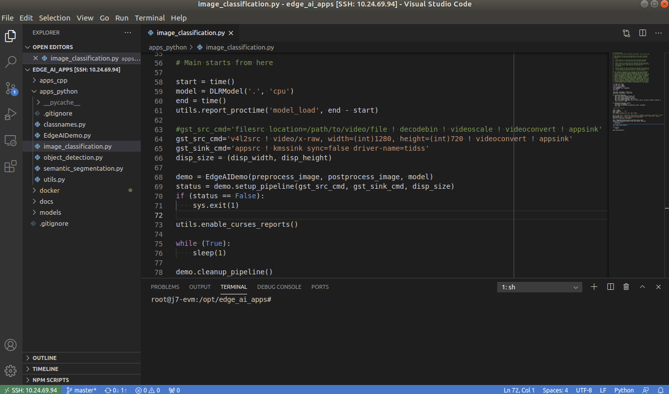
Fig. 10 Microsoft Visual Studio Code for connecting to TDA4VM Starter Kit for Edge AI via SSH
Installing Dependencies
On a fresh install, you need to first run setup_script.sh as below,
root@j7-evm:/opt/edge_ai_apps#./setup_script.sh
This takes care of installing all the dependencies required to run the demo applications,
Clone Tensorflow repo and dependencies to get header files required to build C++ applications
Clone ONNX-RT repo and dependencies to get header files required to build C++ applications
Clone the edgeai-tiovx-modules repo, build and install the modules library.
Clone the edgeai-gst-plugins repo, build and install the custom GStreamer plugins.
Clone the edgeai-tidl-tools repo for running standalone inference examples and Jupyter notebooks
Compile the C++ apps under apps_cpp folder
Warning
Without installing these dependencies, the Python and C++ demos under edge_ai_apps will not run.
Note
We can run the setup_script.sh multiple times. The script checks for what is already downloaded and then executes the next steps like build and install if applicable.
If the scripts are executed on Yocto Linux then we need to re-run the setup_script.sh when switching to a Docker session. This is because of the differences between GLIB version in Yocto Linux and Ubuntu 20.04 Docker image.
The same applies when switching from Docker back to Yocto Linux. The setup_script.sh must be run once before running any other applications or demos.
Debug option can be passed to setup_script.sh as shown below to build apps, modules and plugins in debug mode
root@j7-evm:/opt/edge_ai_apps#./setup_script.sh -d
By default /opt directory is used for downloading and installing the dependencies. A different installation directory can be provided as follows:
root@j7-evm:/opt/edge_ai_apps#./setup_script.sh -i /absolute/path/to/directory
Note
In case you are behind VPN, the script will not work since proxy is not handled for tools like git and wget. As a workaround the script can be executed in a docker container. Please refer to Docker Environment for building and running a docker container. Alternatively you can mount the SD card on a linux PC and run the script, make sure you have write permission to the SD card.