

|
|
Capture driver interface for CC32XX devices.
This driver uses a general purpose timer hardware peripheral to implement the capture functionality. The capture driver only uses half of a timer peripheral (16-bit timer). This is not a software limitation but due to the general purpose timer hardware implementation. For CC32XX devices, the system clock is 80 MHz. A 16-bit timer peripheral has 24-bits of resolution when the prescaler register is used as an 8-bit linear extension.
Each general purpose timer block contains two timers, Timer A and Timer B, that can be configured to operate independently. This behavior is managed through a set of resource allocation APIs. For example, the TimerCC32XX_allocateTimerResource API will allocate a timer for exclusive use. Any attempt to re-allocate this resource by the TimerCC32XX, PWMCC32XX, or CaptureCC32xx drivers will result in a false value being returned from the allocation API. To free a timer resource, the TimerCC32XX_freeTimerResource is used. The application is not responsible for calling these allocation APIs directly.
This device implementation only works with the following modes for Capture_Mode :
#include <stdbool.h>#include <stdint.h>#include <ti/drivers/Capture.h>#include <ti/drivers/Power.h>#include <ti/drivers/dpl/HwiP.h>#include <ti/devices/cc32xx/inc/hw_ints.h>#include <ti/devices/cc32xx/inc/hw_ocp_shared.h>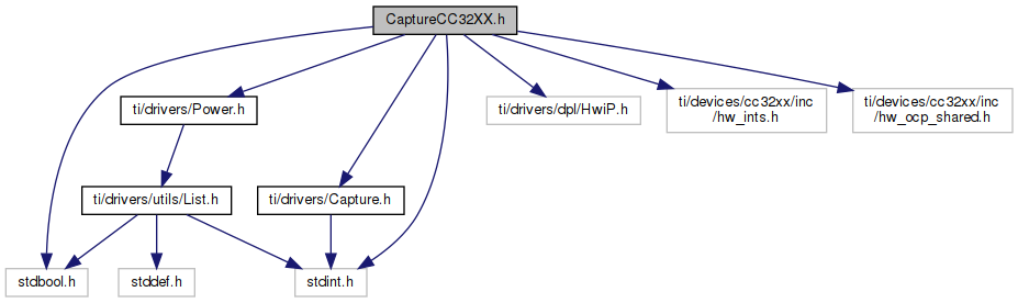
Go to the source code of this file.
Data Structures | |
| struct | CaptureCC32XX_HWAttrs |
| CaptureCC32XX Hardware Attributes. More... | |
| struct | CaptureCC32XX_Object |
| CaptureCC32XX_Object. More... | |
Macros | |
PIN 01, GPIO10, uses Timer0B for Capture. | |
| #define | CaptureCC32XX_PIN_01 |
PIN 02, GPIO11, uses Timer1A for Capture. | |
| #define | CaptureCC32XX_PIN_02 |
PIN 03, GPIO12, uses Timer1B for Capture. | |
| #define | CaptureCC32XX_PIN_03 |
PIN 04, GPIO13, uses Timer2A for Capture. | |
| #define | CaptureCC32XX_PIN_04 |
PIN 05, GPIO14, uses Timer2B for Capture. | |
| #define | CaptureCC32XX_PIN_05 |
PIN 06, GPIO15, uses Timer3A for Capture. | |
| #define | CaptureCC32XX_PIN_06 |
PIN 07, GPIO16, uses Timer3B for Capture. | |
| #define | CaptureCC32XX_PIN_07 |
PIN 15, GPIO22, uses Timer2A for Capture. | |
| #define | CaptureCC32XX_PIN_15 |
PIN 17, GPIO24 (TDO), uses Timer3A for Capture. | |
| #define | CaptureCC32XX_PIN_17 |
PIN 50, GPIO0, uses Timer0A for Capture. | |
| #define | CaptureCC32XX_PIN_50 |
PIN 53, GPIO30, uses Timer2B for Capture. | |
| #define | CaptureCC32XX_PIN_53 |
PIN 55, GPIO1, uses Timer0B for Capture. | |
| #define | CaptureCC32XX_PIN_55 |
PIN 57, GPIO2, uses Timer1A for Capture. | |
| #define | CaptureCC32XX_PIN_57 |
PIN 60, GPIO5, uses Timer2B for Capture. | |
| #define | CaptureCC32XX_PIN_60 |
PIN 61, GPIO6, uses Timer3A for Capture. | |
| #define | CaptureCC32XX_PIN_61 |
PIN 63, GPIO8, uses Timer3A for Capture. | |
| #define | CaptureCC32XX_PIN_63 |
PIN 64, GPIO9, uses Timer0A for Capture. | |
| #define | CaptureCC32XX_PIN_64 |
Variables | |
| const Capture_FxnTable | CaptureCC32XX_fxnTable |
| const Capture_FxnTable CaptureCC32XX_fxnTable |