

|
|
PWM driver implementation for CC26XX/CC13XX.
The general PWM API should be used in application code, i.e. PWM_open() should be used instead of PWMTimerCC26XX_open(). The board file will define the device specific config, and casting in the general API will ensure that the correct device specific functions are called.
Before using PWM on CC26XX:
If providing unsupported arguments to an API returning an error code, the PWM configuration will not be updated and PWM will stay in the mode it was already configured to.
The TI-RTOS power management framework will try to put the device into the most power efficient mode whenever possible. Please see the technical reference manual for further details on each power mode.
The PWMTimerCC26XX.h driver is not explicitly setting a power constraint when the PWM is running to prevent standby as this is assumed to be done in the underlying GPTimer driver. The following statements are valid:
The PWM output period and duty cycle are limited by the underlying timer. In PWM mode the timer is effectively 24 bits which results in a minimum frequency of 48MHz / (2^24-1) = 2.86Hz (349.525ms) The driver will round off the configured duty and period to a value limited by the timer resolution and the application is responsible for selecting duty and period that works with the underlying timer if high accuracy is needed. The effect of this is most visible when using high output frequencies as the available duty cycle resolution is reduced correspondingly. For a 24MHz PWM only a 0%/50%/100% duty is available as the timer uses only counts 0 and 1. Similarly for a 12MHz period the duty cycle will be limited to a 12.5% resolution. The PWM signals are generated using the high-frequency clock as source.
If very high-accuracy outputs are needed, the application should request using the external HF crystal:
The below example will output a 8MHz PWM signal with 50% duty cycle.
#include <stdint.h>#include <stdbool.h>#include <ti/drivers/PIN.h>#include <ti/drivers/PWM.h>#include <ti/drivers/timer/GPTimerCC26XX.h>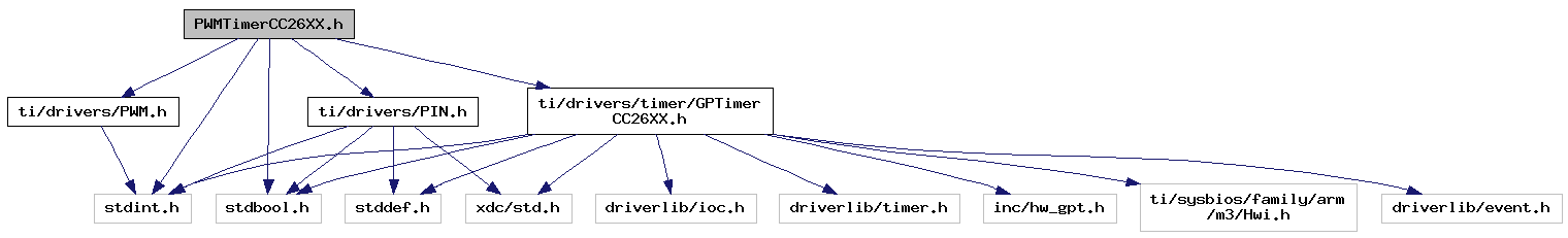
Go to the source code of this file.
Data Structures | |
| struct | PWMTimerCC26XX_HwAttrs |
| PWMTimer26XX Hardware attributes. More... | |
| struct | PWMTimerCC26XX_Object |
| PWMTimer26XX Object. More... | |
Macros | |
| #define | PWMTimerCC26XX_CMD_DEBUG_STALL PWM_CMD_RESERVED + 0 |
| #define | CMD_ARG_DEBUG_STALL_OFF (uint32_t)GPTimerCC26XX_DEBUG_STALL_OFF |
| #define | CMD_ARG_DEBUG_STALL_ON (uint32_t)GPTimerCC26XX_DEBUG_STALL_ON |
Typedefs | |
| typedef const struct PWMTimerCC26XX_HwAttrs | PWMTimerCC26XX_HwAttrs |
| PWMTimer26XX Hardware attributes. More... | |
| typedef struct PWMTimerCC26XX_Object | PWMTimerCC26XX_Object |
| PWMTimer26XX Object. More... | |
| #define PWMTimerCC26XX_CMD_DEBUG_STALL PWM_CMD_RESERVED + 0 |
PWMTimerCC26XX specific commands
Timer debug stall mode (stop PWM output debugger halts CPU) When enabled, PWM output will be HIGH when CPU is halted
| #define CMD_ARG_DEBUG_STALL_OFF (uint32_t)GPTimerCC26XX_DEBUG_STALL_OFF |
| #define CMD_ARG_DEBUG_STALL_ON (uint32_t)GPTimerCC26XX_DEBUG_STALL_ON |
| typedef const struct PWMTimerCC26XX_HwAttrs PWMTimerCC26XX_HwAttrs |
PWMTimer26XX Hardware attributes.
These fields are used by the driver to set up underlying PIN and GPTimer driver statically. A sample structure is shown below:
| typedef struct PWMTimerCC26XX_Object PWMTimerCC26XX_Object |
PWMTimer26XX Object.
These fields are used by the driver to store and modify PWM configuration during run-time. The application must not edit any member variables of this structure. Appplications should also not access member variables of this structure as backwards compatibility is not guaranteed. A sample structure is shown below:

