15.16.3. Scenario 3 – Hex Conversion Command File for Two 8-Bit EPROMs
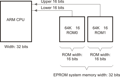
Scenario 3 shows how to build the hex conversion command file for converting an object file for the memory system shown in the following figure. In this system, there are two external 64K × 16-bit EPROMs interfacing with the TMS470 target processor. The application code and data will be burned on the EPROM starting at address 0x20. The application code will be burned first, followed by the data tables.
Figure: EPROM Memory System for Scenario 3
In this scenario, the EPROM load address for the application code and for the data also corresponds to the TMS470 CPU address that accesses the code and data. Therefore, only a load address needs to be specified.
The following linker command files contains the MEMORY and SECTIONS directives for this scenario:
Example: Linker Command File for Scenario 3
/****************************************************************************/
/* Scenario 3  Link Command                                                 */
/*                                                                          */
/*   Usage: armlnk <obj files...>    -o <out file> -m <map file> lnk32.cmd  */
/*          tiarmclang <src files...> -Wl,-o=out_file,-m=map_file lnk32.cmd */
/*                                                                          */
/*   Description: This file is a sample command file that can be used       */
/*                for linking programs built with the TMS470 C              */
/*                compiler.   Use it as a guideline; you may want to change */
/*                the allocation scheme according to the size of your       */
/*                program and the memory layout of your target system.      */
/*                                                                          */
/*   Notes: (1)   You must specify the directory in which rts32.lib is      */
/*                located.  Either add a "-i<directory>" line to this       */
/*                file, or use the system environment variable C_DIR to     */
/*                specify a search path for libraries.                      */
/*                                                                          */
/*          (2)   If the runtime-support library you are using is not       */
/*                named rts32.lib, be sure to use the correct name here.    */
/****************************************************************************/

-m example3.map

/* SPECIFY THE SYSTEM MEMORY MAP */
MEMORY
{
    I_MEM    : org = 0x00000000   len = 0x00000020  /* INTERRUPTS           */
    D_MEM    : org = 0x00000020   len = 0x00010000  /* DATA MEMORY    (RAM) */
    P_MEM    : org = 0x00010020   len = 0x00100000  /* PROGRAM MEMORY (ROM) */
}

/* SPECIFY THE SECTIONS ALLOCATION INTO MEMORY */
SECTIONS
{
    secA: load = 0x20
    secB: load = D_MEM
}
You must create a hex conversion command file to generate a hex output with the correct addresses and format for the EPROM programmer.
The EPROM programmer in this scenario has the following system requirements:
In the memory system outlined in the previous figure the EPROM system memory width is 32 bits because each of the physical ROMs provides 16 bits of a 32-bit word. Because the EPROM system memory width is 32 bits, the memwidth value must be set to 32.
Because the width of each of the physical ROMs is 16 bits, the romwidth value must be set to 16.
Intel format must be used.
With a memwidth of 32 and a romwidth of 16, two output files are generated by the hex conversion utility (the number of files is determined by the ratio of memwidth to romwidth). In previous scenarios, the output filename was specified with the -o option. Another way to specify the output filename is to use the files keyword within a ROMS directive. When you use -o or the files keyword, the first output filename always contains the low-order bytes of the word.
The hex conversion command file for Scenario 3 is shown in the example that follows. This command file uses the following options to select the requirements of the system:
Option |
Description |
|---|---|
-i |
Create Intel format |
-map example3.mxp |
Generate example3.mxp as the map file of the conversion |
-memwidth 32 |
Set EPROM system memory width to 32 |
-romwidth 16 |
Set physical ROM width to 16 |
The files keyword is used within the ROMS directive to specify the output filenames.
Example: Hex Conversion Command File for Scenario 3
/* Hex Conversion Command file for Scenario 3               */
a.out                  /* linked object file, input         */
-I                     /* Intel format */

/* Optional Commands */
-map example3.mxp      /* Generate a map of the conversion  */

/* Specify EPROM system memory width and physical ROM width */
-memwidth 32           /* EPROM memory system width         */
-romwidth 16           /* Physical width of ROM             */

ROMS
{
    EPROM: org = 0x0, length = 0x20000
    files={ lower16.bit, upper16.bit }
}
The resulting map file (example3.mxp) is as follows:
Example: Contents of Hex Map File example3.mxp
**********************************************************
TMS470 Hex Converter Version x.xx
**********************************************************
Tue Sep 19 07:41:28 1995
INPUT FILE NAME: <a.out>
OUTPUT FORMAT: Intel
PHYSICAL MEMORY PARAMETERS
Default data width: 8
Default memory width: 32
Default output width: 16
OUTPUT TRANSLATION MAP
---------------------------------------------------------
00000000..0001ffff Page=0 ROM Width=16 Memory Width=32 "EPROM"
---------------------------------------------------------
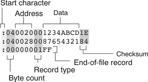
OUTPUT FILES: lower16.bit [b0..b15]
upper16.bit [b16..b31]
CONTENTS: 00000020..00000021 Data Width=1 secA
00000028..00000029 Data Width=1 secB
The contents of the output files lower16.bit and upper16.bit are shown in the following two figures, respectively. The low-order 16 bits of the 32-bit output word are stored in the lower16.bit file, while the upper 16 bits are stored in the upper16.bit file.
Figure: Contents of Hex Output File lower16.bit
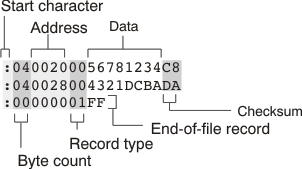
Figure: Contents of Hex Output File upper16.bit