TI 15.4-Stack Overview
This chapter explains in detail the three different network configuration modes
supported by the TI 15.4-Stack for application development. Useful information is
presented for developers using TI 15.4-Stack for their custom application
development, which lets developers quickly understand the basics of the
selected configuration mode and develop their end products with ease. The stack
operating mode can be performed in three different channel bands and at
different PHY data rates (200 kbps, 50 kbps, or 5 kbps). The choice of
PHY band and data rate can be made by setting the appropriate PHY Id in
ApiMac_attribute_phyCurrentDescriptorId PIB attribute. The overall options
are explained in Table 1.
| PHY ID | PHY Data Rate | Channel 0 Freq | # of Channels | Channel Spacing |
|---|---|---|---|---|
| 1 | 50kbps | 902.2 | 129 | 200KHz |
| 3 | 50kbps | 863.125 | 34 | 200KHz |
| 128 | 50kbps | 403.3 | 7 | 200KHz |
| 129 | 5kbps | 902.2 | 129 | 200KHz |
| 130 | 5kbps | 403.3 | 7 | 200KHz |
| 131 | 5kbps | 863.125 | 34 | 200KHz |
| 132 | 200kbps | 902.4 | 64 | |
| 133 | 200kbps | 863.225 | 17 |
Attention
The 200kbps modes are only supported using a beacon-enabled network for this release.
Beacon Enabled Mode
Introduction
The IEEE 802.15.4 specification defines beacon-enabled mode of operation where the personal area network (PAN) coordinator device transmits periodic beacons to indicate its presence and allows other devices to perform PAN discovery and synchronization. The beacons provide beacon-related information and also mark the start of the new super-frame. The beacon has information on the super-frame specification, which helps the device intending to join the network to synchronize timing and network related parameters before starting the join process. The beacon helps the existing device in the PAN to maintain the network synchronization. The super-frame is divided into an active and an inactive period. During the active period, devices communicate using the CSMA/CA procedure except in 863MHz band where LBT is used for channel access. The inactive period allows the devices in the network to conserve energy.
Network Operations
This section describes critical network operations for the beacon-enabled mode of operation.
Network Start-Up
A network is always started by a fully functional device after performing a MAC sublayer reset. The network operates on a single channel (frequency hopping is not available in this configuration, although frequency agility may be implemented by application-specific means). To select the most optimal channel of operation, the fully functional device (before starting the network) can optionally scan for the channels with the least amount of radio interference by first performing the energy-detect scan to identify the list of channels with the least amount of RF energy. When a list of channels is identified, the fully functional device can (optionally) perform active scan to find the channel with the least number of active networks. When the channel with the least RF energy and lowest number of active networks is selected, the PAN coordinator must set its short address (the PAN identifier) beacon payload and turn on the associate permit flag. The network starts upon the following actions:
- Call to
ApiMac_mlmeStartReq()API- With the PAN coordinator parameter set to TRUE
- With the desired super-frame configuration
- Coordinator realignment parameter set to FALSE
Figure 23. shows the interaction between the application and TI 15.4-Stack to start the beacon-enabled network by the PAN coordinator.
Figure 23. Beacon Mode Network Start-Up Sequence
Network Association
A device that is intended to join the beacon-enabled network must first perform a passive channel scan. The results of the channel scan can then be used to choose a suitable network. Following the selection of an association network, the application should set the following PIB items:
ApiMac_attribute_beaconOrder- Set to the value received in the beacon super-frame specification of the chosen PAN
ApiMac_attribute_superframeOrder- Set to the value received in the beacon super-frame specification of the chosen PAN
ApiMac_attribute_panId- PAN identifier of the PAN
ApiMac_attribute_coordShortAddress- Short address of the PAN coordinator
The next step is to perform beacon synchronization to track the beacon and to
detect any pending messages. Synchronization is requested by using the
ApiMac_mlmeSyncReq() API call and setting the following parameters:
- Channel
- PHY identifier
- Channel page
- Setting track beacon to TRUE
To acquire beacon synchronization, the device searches for the maximum time calculated as follows:

and

Refer to the IEEE 802.15.4 specification for the definition of previous constants.
The device must to wait for the previously stated time period for the
synchronization process to complete. Alternatively the device can turn off the
Auto Request by setting the ApiMac_attribute_autoRequest attribute item to
FALSE, which forces the MAC sublayer to send the beacon notification to the
upper layer. If the application receives beacon notification indications for
the normal beacon and no sync loss indication, it is a good indication that the
device has synchronized with the coordinator beacons. TI recommends waiting for
at least two beacon notifications before turning on the Auto Request.
When the device is synchronized to the network and is tracking the beacon, the
application can perform the network association. The
ApiMac_mlmeAssociateReq() API call is used to send the association request
message to the coordinator. The association process is successful when the
application receives the association confirmation.
Figure 24. shows a device performing the network association.
Figure 24. Beacon Mode Device Association Sequence
Data Exchange
The sequence diagram in Figure 25. depicts the various direct data transactions between an always-on (mains powered) device and a coordinator in a beacon-enabled network.
Figure 25. Beacon Mode Direct Data Exchange Sequence
The sequence diagram in Figure 26. depicts the indirect data transaction in a beacon-enabled network.
Figure 26. Beacon Mode Indirect Data Exchange Sequence
Maintaining a Connection for End Nodes
All devices operating on a beacon-enabled PAN must acquire beacon synchronization with a coordinator. Synchronization is performed by receiving and decoding the beacon frame information. The beacon frame contains the super- frame specification which lets the device sync its timing information with the coordinator and detect any pending messages.
During the network association phase, the end device calls the
ApiMac_mlmeSyncReq() API with the trackBeacon parameter set to TRUE to
acquire beacon and keep track of it (see Figure 27.
). With the track beacon set to TRUE, the MAC sublayer shall enable
its receiver at a time before the next expected beacon frame transmission. If
the number of consecutive beacons missed by the MAC sub layer reaches the
maximum allowed (four beacons), the TI 15.4-Stack makes a callback
ApiMac_syncLossIndFp_t() with a status of ApiMac_status_beaconLoss to
the application. The application tries to resynchronize with the coordinator by
calling ApiMac_mlmeSyncReq() with trackBeacon set to TRUE.
Figure 27. Beacon Mode Sync Loss Sequence
Network Disassociation
This section describes three scenarios. The first two scenarios are initiated by the coordinator (one for the mains powered end device and the other for the battery powered end device). In the third scenario, the end device disassociates itself from the network.
When the coordinator application requires an associated device to leave the
network, the coordinator application requests that TI 15.4-Stack sends a
disassociation notification command by using the
ApiMac_mlmeDisassociateReq() call. If the txIndirect parameter is set
to TRUE, the TI 15.4-Stack sends the disassociation notification command to the
device using indirect transmission; then, the disassociation notification
command is added to the list of pending transactions stored on the coordinator
and pulled by the device using a data request command (see
Figure 28.).
Figure 28. Beacon Mode Coordinator Initiated Indirect Disassociation Sequence
If the txIndirect parameter is set to FALSE, TI 15.4-Stack sends the
disassociation notification command frame to the device using direct
transmission (see Figure 29.).
The TI 15.4-Stack layer at the coordinator makes a callback to the application
using the registered function pointer of type ApiMac_disassociateCnfFp_t
after completion of the disassociation. TI 15.4-Stack at the end-device makes a
callback to the application using the registered function pointer of type
ApiMac_disassociateIndFp_t on reception of the disassociation notification
command frame from the coordinator.
Figure 29. Beacon Mode Coordinator-Initiated Direct Disassociation Sequence
The end-device application can also initiate the disassociation process as described in Figure 30..
Figure 30. Beacon Mode Device-Initiated Disassociation Sequence
Stack Configuration Knobs
Attribute Configuration
Table 2. lists the attribute configuration for beacon mode.
| Name | Type | Range | API Number | Description |
|---|---|---|---|---|
| ApiMac_attribute_associatePermit | bool | TRUE, FALSE | 0x41 | TRUE if a coordinator is currently allowing association |
| ApiMac_attribute_autoRequest | bool | TRUE, FALSE | 0x42 | TRUE if a device automatically sends a data request if its address is listed in the beacon frame |
| ApiMac_attribute_beaconOrder | uint8 | 0–15 | 0x47 | How often the coordinator transmits a beacon |
| ApiMac_attribute_RxOnWhenIdle | bool | TRUE, FALSE | 0x52 | TRUE if the MAC enables its receiver during idle periods |
| ApiMac_attribute_superframeOrder | uint8 | 0–15 | 0x54 | This specifies the length of the active portion of the superframe. |
The ApiMac_attribute_associatePermit is used by the coordinator application
to indicate to the joining devices whether it allows association or not.
Setting this attribute item to TRUE by the coordinator indicates to the joining
devices in its beacon frame that the coordinator application allows
association.
The ApiMac_attribute_RxOnWhenIdle, if set to TRUE, enables the receiver
during the idle period.
The ApiMac_attribute_RxOnWhenIdle, if set to TRUE, enables the receiver
during the idle in the contention period of the super-frame. The coordinator
application sets this item to TRUE.
The ApiMac_attribute_beaconOrder item is used by the device application to
set the beacon order during the joining phase, after the passive scan of
beacons, and after the device makes the decision on which coordinator to join.
This attribute shall be set to the selected coordinators beacon order value.
The ApiMac_attribute_superframeOrder item is used by the device application
to set the super-frame order during the joining phase, after the passive scan
of beacons, and after the device makes the decision on which coordinator to
join. This attribute shall be set to the selected coordinators beacon order
value.
Configuration Constants
TI 15.4-Stack uses a structure containing various user-configurable parameters
(at compile time). This structure, called macCfg_t, is in the mac_cfg.c
file. Table 3. describes the configuration
elements.
| Name | Description | Range | Default |
|---|---|---|---|
| txDataMax | Maximum number of data frames queued in the transmit data queue. | 1–255 | 2 |
| txMax | Maximum number of frames of all types queued in the transmit data queue. | 1–255 | 5 |
| rxMax | Maximum number of frames queued in the receive data queue. | 1–255 | 2 |
| dataIndOffset | Allocate additional bytes in the data indication for application-defined headers. | 0–127 | 0 |
| appPendingQueue | When TRUE, registered callback of type ApiMac_pollIndFp_t will be made to the application when a data request command frame is received from another device. | TRUE or FALSE | FALSE |
Nonbeacon Mode
Introduction
The IEEE 802.15.4 specification defines the non-beacon mode of network operation where the coordinator does not send out periodic beacons. The non- beacon mode is an asynchronous network mode of operation where the devices communicate by using the CSMA/CA mechanism.
Network Operations
Network Start-Up
A network is always started by a full function device. The procedure to start
the network begins with a MAC layer reset. The application can directly start
the network on a desired channel with a desired or random PAN-ID, or it can
first check for a channel with lowest RF energy by performing a energy detect
scan to select the channel with lowest energy or least interference (see
Figure 31.). The application then
performs an active scan to detect the existing networks in the area, and
select network parameters for its own network which do not conflict. After
selecting the channel, the PAN Coordinator application must set the short
address and PAN-ID, and then set the beacon payload and (optionally) turn
on the associate permit flag if it wants new devices to join the network.
The network is then started using the API ApiMac_mlmeStartReq() with the
panCoordinator parameter set to TRUE.
Figure 31. Nonbeacon Mode Network Start-Up Sequence
Network Join
When a device is ready to join a non-beacon network, it must first perform an
active scan broadcasting a beacon request. After receiving the beacon request,
the non-beacon PAN coordinators in the radio range of the device respond with
their beacons. When the scan is complete, TI 15.4-Stack calls the registered
callback of type ApiMac_scanCnfFp_t with the PAN descriptors of the beacons
it has received during the scan to the device application. The device
application examines the PAN descriptors and selects a coordinator.
The next step is to perform the network association (see
Figure 32.). The device application calls
the ApiMac_mlmeAssociateReq() API to send the association request
message to the coordinator. The association process is successful when the
device application receives the association confirmation from the TI
15.4-Stack layer.
Figure 32. Nonbeacon Mode Device Association Sequence
Data Exchange
The sequence diagram in Figure 33. depicts the various direct data transactions between a device and a coordinator in a non-beacon network.
Figure 33. Non-beacon Mode Direct Data Exchange Sequence
The sequence diagram in Figure 34. depicts the indirect data transaction in a non-beacon network.
Figure 34. Non-beacon Mode Indirect Data Exchange Sequence
Maintaining a Connection for End Nodes
If the device application receives repeated communication failures following requests to transmit data, the device application may conclude that it has been orphaned and can initiate an orphaned-device realignment procedure. Figure 35. shows the non-beacon mode orphan sequence.
In the orphan realignment procedure, the device application requests TI
15.4-Stack to perform the orphan scan over a specified set of channels by using
the ApiMac_MlmeScanReq() API with the scan-type parameter set to orphan
scan. For each channel specified, TI 15.4-Stack at the device switches to the
channel and then sends an orphan notification command. After successfully
transmitting the orphan notification command, the MAC layer enables the
receiver for at most ApiMac_attribute_responseWaitTime. If the device
successfully receives a coordinator realignment command, the device terminates
the scan and calls the registered callback of type ApiMac_scanCnfFp_t. At
the coordinator side, the reception of the orphan notification command results
in the call of the registered callback of type ApiMac_orphanIndFp_t by TI
15.4-Stack. If the coordinator application finds the record of the device, it
sends a coordinator realignment command to the orphaned device by using the
ApiMac_MlmeOrphanRsp() call.
Figure 35. Nonbeacon Mode Orphan Sequence
Disassociating
Two scenarios are described in the following: the first is initiated by the coordinator and the second is initiated by the device. Figure 36. shows the indirect disassociation sequence initiated by the non-beacon mode coordinator.
When the coordinator application wants one of the associated devices must leave
the PAN, the coordinator application requests that TI 15.4-Stack send the
disassociation notification command by using the
ApiMac_mlmeDiassociateReq() call. If the txIndirect parameter is set to
TRUE, TI 15.4-Stack sends the disassociation notification command to the device
using indirect transmission; then, the disassociation notification command is
added to the list of pending transactions stored on the coordinator and pulled
by the device using data request command.
Figure 36. Indirect Disassociation Sequence Initiated by the Non-beacon Mode Coordinator
The end device application can also initiate the disassociation process as described in Figure 37., which shows the sequence of messages exchanged when the end device initiates the disassociation process in the non-beacon network.
Figure 37. Disassociation Sequence Initiated by the Nonbeacon Mode Device
Stack Configuration Knobs
Attribute Configuration
The ApiMac_attribute_associatePermit is used by the coordinator application
to indicate to the joining devices whether association is allowed or not. When
the coordinator sets this attribute item to TRUE, this indicates to the joining
devices within the beacon frame that association is allowed.
Table 4. lists the attribute configurations that
apply to non-beacon mode.
If set to TRUE, the ApiMac_attribute_RxOnWhenIdle enables the receiver
during the idle period.
| Name | Type | Range | Number | Description |
|---|---|---|---|---|
| ApiMac_attribute_associatePermit | Bool | TRUE, FALSE | 0x41 | TRUE if a coordinator is currently allowing association. |
| ApiMac_attribute_RxOnWhenIdle | Bool | TRUE, FALSE | 0x52 | TRUE if the MAC enables its receiver during idle periods. |
Configuration Constants
TI 15.4-Stack uses a structure containing various user-configurable parameters
(at compile time). This structure, called macCfg_t, is in the mac_cfg.c
file. Table 5. lists the configuration
elements.
| Name | Description | Range | Default |
|---|---|---|---|
| txDataMax | Maximum number of data frames queued in the transmit data queue. | 1 – 255 | 2 |
| txMax | Maximum number of frames of all types queued in the transmit data queue. | 1 – 255 | 5 |
| rxMax | Maximum number of frames queued in the receive data queue. | 1 – 255 | 2 |
| dataIndOffset | Allocate additional bytes in the data indication for application-defined headers. | 0 – 127 | 0 |
| appPendingQueue | When TRUE, registered callback of type ApiMac_pollIndFp_t will be made to the application when a data request command frame is received from another device. | TRUE – FALSE | FALSE |
Frequency-Hopping Mode
Introduction
Applications that are developed using TI 15.4-Stack can be configured to operate the network in frequency-hopping configuration where the network devices hop on different frequencies. TI 15.4-Stack supports an unslotted channel-hopping feature based on the directed frame exchange (DFE) mode of the Wi-SUN FAN specification v1.0.
Two types of end devices are supported:
- Sleepy End Device: These devices do not change channels by themselves but follow that of the collector. All communication to these devices should be made using short addressing.
- Non-Sleepy End Device: These devices can either hop on multiple channels based on direct hash channel function (DH1CF) or operate on a fixed channel based on the channel function configuration. All communication to these devices should be made using extended address mode.
The Collector device can either hop on multiple channels based on direct hash channel function DH1CF or operate on a fixed channel based on the channel function configuration.
DH1CF generates a pseudo-random sequence of channels on which to hop based on the extended address of the node; thus, the pseudo-random sequence of channels is unique to each node. Each node supports two types of channel-hopping sequences:
- Unicast
- Broadcast
Frequency hopping for each node is based on the unicast channel hopping sequence of those nodes (see Figure 38.).
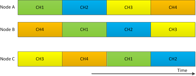
Figure 38. Unicast Hopping Sequence
To enable broadcast transmissions, the coordinator starts a broadcast schedule (see Figure 39.). Every other device follows the broadcast-hopping sequence received from the PAN coordinator. A device performs unicast hopping until the next broadcast dwell time. Then, the device switches to the broadcast- hopping channel for the broadcast dwell time and resumes unicast hopping at the end of the broadcast dwell interval.
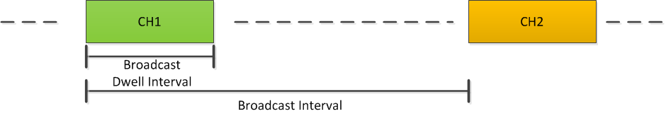
Figure 39. Broadcast Channel Hopping Sequence
The application can specify the broadcast dwell interval (default is 250 ms),
channel hopping function (default is Fixed Channel), and the list of channels
to hop (based on PHY Descriptor ID; for example, the default value of 1
represents 129 channels). Additionally, the broadcast interval (default is 4250
ms) can be specified on the PAN coordinator. When the hopping function is set
to Fixed, the node must stay on the channel set by
ApiMac_FHAttribute_unicastFixedChannel or
ApiMac_FHAttribute_broadcastFixedChannel during the unicast and broadcast
dwell times, respectively.
Note
The broadcast dwell time can be set to 0 to disable broadcast transmission. This can be especially helpful in saving power on sleepy end devices when broadcast transmission are not used in application as the device would no longer be required to power up during broadcast slots.
Note
A set of channels can also be excluded from the hopping channels by using
the ApiMac_FHAttribute_unicastExcludedChannels and
ApiMac_FHAttribute_broadcastExcludedChannels PIBs as defined in
Stack Configuration Knobs.
A special type of transmission called async transmission is also supported. In frequency-hopping mode, a device transmits any one of the Async frame types (as defined in the Wi-SUN FAN specification) in all of the requested channels (see Wi-SUN FAN Specification). This enables a hopping device to receive such a frame irrespective of the hopping sequence. Thus, the async transmission can be used to exchange channel-hopping information. This feature is especially useful in initial network formation as explained in Network Join.
When channel-hopping information of a neighbor is received, TI 15.4-Stack
tracks the hopping sequences of the neighbor hopping devices and enables
successful unicast and broadcast transmissions; thus, hiding the complexities
of maintaining synchronization from the application and easing the task of
developing applications with frequency hopping feature. To support short
address mode the FH_COORD_SHORT_ADDRESS should be configured on end device
to match the short address of the collector used.
Network Operations
In frequency hopping mode, nodes operate as one of the following device types:
- PAN coordinator
- Non-sleepy device
- Sleepy device
A typical star topology has a single PAN coordinator connected to a set of non-sleepy or sleepy devices. Each network is identified by a specific network name, which is an ASCII value of 32 bytes and a 16-bit PAN Identifier. The network name (NetName) is a unique network identifier that is configured by the application using frequency hopping and PAN information base (FH-PIB) attributes. Maintenance of the NetName is beyond the scope of TI 15.4-Stack and is not used to filter frames.
The sections below explain various network operations important to understand when developing a frequency hopping-enabled network over TI 15.4-Stack.
Network Start-Up
Figure 40. shows how a frequency-hopping network is started by starting the PAN coordinator in frequency-hopping mode.
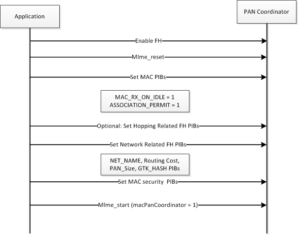
Figure 40. Start-Up Sequence of PAN Coordinator
The PIB attributes that are related to frequency-hopping configuration are explained in Stack Configuration Knobs. The NetName is a 32-bit ASCII value to be set by the application. The routing cost must be set to zero.
Initially, the PAN size must be set to zero; later, the PAN size must be updated based upon the number of nodes joined.
Note
This NetName value is not used by the TI 15.4-Stack to make any decision; instead, the value is carried in a PAN Advertisement frame that can be parsed by a receiving application. Similarly, the GTK HASH 0, GTK HASH 1, GTK HASH2, and GTK HASH 3 can be used to determine the validity of GMK keys that are in use and are beyond the scope of TI 15.4-Stack.
Finally, start MAC using the macStart API, which specifies that the node is a coordinator.
Device Start-Up
Figure 41. shows the start-up sequence of the device.
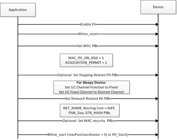
Figure 41. Start-Up Sequence of the Device
Wi-SUN FAN v1.0 does not specify sleep mode operation, but the TI 15.4-Stack implements a proprietary extension over the behavior defined in the Wi-SUN FAN and IEEE 802.15.4 MAC protocols (see Sleep Mode Operation) to enable sleepy devices in the frequency-hopping networks based on TI 15.4-Stack. The channel-hopping function for a sleepy device must be set to Fixed, and the fixed channel can be set to any desired channel. The security keys can be set at start-up (if the security keys are already pre-configured for the network), or the security keys can be set after obtaining the same through a key exchange. The key exchange protocol must be handled above the MAC layer.
The routing cost must be set to a high value (0xFFFF) to indicate that the device has not joined the network; later, it can be updated by the application based on the routing metric used.
Note
The sequence to start the sleepy and non-sleepy devices is the same until they join a network. A sleepy device is configured to be sleepy by setting the MAC PIB (macRxOnWhenIdle) to zero only after it joins the network (see Network Join). In other words, the sleep mode operation uses low-power mode only for data exchange after successfully joining the network.
Network Join
To join to a network, a node must go through the two phases described as follows.
Phase 1: Exchange of Channel-Hopping Sequence Information Through Asynchronous Messages
Asynchronous messages are sent back-to-back over a specified channel list. This action enables a receiver to receive such frames with high probability, irrespective of the hopping sequence. Four different asynchronous messages are supported by TI 15.4-Stack as defined in the Wi-SUN FAN specification. All asynchronous frames are transmitted based on a trickle timer [RFC 6206]. The Imin, Imax, and K for the trickle algorithm are recommended to be set at 1 min, 16 min, and 1, respectively.
Brief descriptions of the four types of asynchronous messages follow:
- PAN Advertisement Solicit (PAS):
- PAS messages are used by a device to request a coordinator or other joined nodes to transmit a PAN Advertisement frame.
- Upon reception of the PAN Advertisement frame, a joining application can detect the NetName IE in the frame and then use the name to determine whether or not to reset PA trickle timer.
- PAN Advertisement (PA):
- PA frames can be transmitted by a coordinator or by a joined node to inform neighbors about the PAN size, Routing cost, and PAN ID.
- The trickle timer associated with PA transmissions is programmed to be reset on reception of a PAS frame.
- Upon, reception of the PAS frame, nodes communicate with the transmitter of the PA frames (note the hopping sequence is carried in the PA frame).
- The device can choose one of the source nodes of the PA frame as relay to perform an Authentication and Secure Key Exchange protocol that must be implemented by the application running over the TI 15.4-Stack. Example applications (collector and sensor) included in TI 15.4- Stack do not demonstrate this feature.
- PAN Configuration Solicit (PCS):
- When a device has the group master key (GMK) keys used in the network, the device can request the transmission of a PAN Configuration frame.
- PCS messages are transmitted by a node to request neighbors or the coordinator transmit a PAN Config frame.
- PAN Configuration (PC):
- PC messages are transmitted by the coordinator or a joined node based on a trickle timer that must be reset upon reception of a PCS frame.
- PC frames carry the broadcast-hopping sequence and the hash values of the list of GMK keys that are actively used.
- Upon reception of a PC frame, a device detects that the channel-hopping exchanges are completed.
When using the frequency-hopping configuration on star-network topology, TI recommends the following:
- The PAN coordinator transmits PA and PC frames based on separate trickle timers. TI recommends that developers refer to the collector example application implementation located under the examples folder in the TI 15.4-Stack installation directory).
- Devices transmit PAS and PCS frames for the purpose of joining; then, the devices suspend the trickle timer after a successful join. TI recommends that developers refer to the sensor example application as a reference on how to implement this action, or that they use the implementation in the sensor example application as-is as a starting point for custom applications.
- Devices must also implement the suppression mechanism to limit the number of PAS and PCS frames transmitted. TI recommends developers refer to the sensor example application (examples folder in the TI 15.4-Stack installation directory) as a reference for implementing this action, or use the implementation in the sensor example application as-is as a starting point for custom applications.
Phase 2: Proprietary Association Procedure to Inform Coordinator of the Network Join (This is an Optional Step)
Because the frequency hopping join procedure (defined by the Wi-SUN specification) is silent, the PAN coordinator cannot detect if the device has successfully joined the network. The TI 15.4-Stack example applications use an additional step for network join. The MAC layer association procedure described in the IEEE 802.15.4 specification is used after the PCS indicates to the PAN coordinator that the device has successfully joined the frequency-hopping network.
In addition to informing the coordinator that the device has successfully joined the network, the optional mechanism allows the PAN coordinator to detect if the joining node is sleepy or always-on through the capability information field of the association request message sent by the device to the PAN coordinator. This optional mechanism is required for the PAN coordinator application to determine the following:
- If the application must buffer the message until the device polls for some configured amount of time in case the message is for a sleepy device
- If the application must send the message OTA as soon as the message- transmit request is generated
Although this step is not required for data exchange (because EUI addresses are used instead of short addresses for communication in frequency-hopping mode), TI recommends using this optional procedure in the applications using the frequency-hopping configuration of the TI 15.4-Stack to enable the coordinator application to build the list of joined nodes and to detect if the newly joined device is sleepy or is an always-on device.
Note
The association procedure must be started at least 2 seconds after
reception of a PAN configuration frame. Upon failure, the association
procedure can be independently retried up to the retry limit of the
application. For a sleepy device, the ApiMac_attribute_RxOnWhenIdle
should be set to zero only after a successful completion of the mac-
association procedure.
Figure 42. and Figure 43. shows the procedure for sleepy and non-sleepy devices, respectively.
Figure 42. Joining Procedure for a Sleepy Frequency-Hopping Device
Figure 43. Joining Procedure for a Nonsleepy Frequency-Hopping Device
Data Exchange
Three types of data-exchange mechanisms are supported by the TI 15.4-Stack:
- Unicast data exchange
- Broadcast data exchange
- Asynchronous frame exchange
Destination address mode should be based on end-device being sleepy or non-
sleepy. To initiate a unicast or broadcast frame exchange, the API
ApiMac_mcpsDataReq should be used. To transmit an asynchronous frame,
ApiMac_mlmeWSAsyncReq should be used. The determination of whether the
message is unicast or broadcast is done based on the destination address mode
used in the data request parameter type ApiMac_mcpsDataReq_t (see
Table 6.).
| Message Type | Source Address Mode | Destination Address Mode | Destination Address |
|---|---|---|---|
| Unicast (sleepy device) | 2 | 2 | Specified by the application |
| Unicast (non-sleepy device) | 3 | 3 | Specified by the application |
| Broadcast | 3/2 | 0 | Ignored by stack |
Unicast Data Exchange
Unicast data exchange in frequency-hopping mode occurs on the channel of the destination node. A node transmits the frame on the expected receive channel of the destination node. The entire frame exchange occurs on the same channel (see Figure 44.). Subsequent data exchange occurs on the channel on which the receiver is hopping at the time of transmission; this subsequent data exchange is independent from earlier transmissions.
Figure 44. Data Exchange With TI 15.4-Stack in Frequency-Hopping Configuration
To transmit a unicast frame to a neighbor, the hopping information was received by the node in some earlier frame. The hopping information could have been received through the reception of any type of asynchronous frames from the destination node. Hence, an application should ensure that such a frame is received from destination node before initiating a data request.
If a data request is issued to a node whose entry is not in the neighbor table,
the error code ApiMac_status_fhNotInNeighborTable (0x64) specifies that the
node that is not in the neighbor table is returned to the application by TI
15.4-Stack. Also, an expiry is associated with each neighbor table entry. The
default time of the expiry is 2 hours for hopping neighbors. The 2 hour default
expiry is set because the hopping information stored in the neighbor table may
not be useful beyond that time limit for a successful data exchange (due to loss
in synchronization caused by inherent clock drifts). Any data exchange helps the
node to resynchronize the entry; thus, the entry is considered active for the
next 2 hours. If a data request is sent for an expired neighbor, the message is
not sent to the destination and a status of ApiMac_status_fhExpiredNode
(0x6C) is returned to the application. Unicast frames are only transmitted in
unicast slots.
Note
The lifetime of a hopping neighbor can be changed to any other desired value
in the range of 5 minutes to 600 minutes (10 hours) by using the PIB
attribute, ApiMac_FHAttribute_neighborValidTime, which is specified in
minutes.
Broadcast Frame Exchange
Broadcast frames are transmitted only during the broadcast dwell interval as
shown in Figure 39.. This can lead to situations where
frames are out of order between a unicast and broadcast frame (that is, the
order in which frames are requested to be transmitted by the application could
be different from the order in which they are transmitted over the air). Thus,
the order in which the ApiMac_mcpsDataReq confirm is received may be
different from the order in which ApiMac_mcpsDataReq is sent. The msdu-
handle should be used to match the request primitive to the corresponding
confirm primitive by the application.
An application on the PAN coordinator can transmit a broadcast frame any time
because the PAN coordinator starts the broadcast hopping as soon as the
application is started. All other nodes should wait for the reception of a PAN
Configuration frame from the PAN coordinator to start the broadcast-hopping
sequence. An application on these other nodes should wait for the reception of
the PAN Configuration frames; then the application can set the source address of
the PAN Configuration frame (if it selects to use that node as a Parent) to the
FH_MAC_TRACK_PARENT PIB before issuing a request of broadcast frame
exchange. If an application issues a broadcast data request while the node has
not yet started following a broadcast hopping sequence, the stack returns an
ApiMac_status_badState (0x19) error code.
Asynchronous Frame Exchange
Asynchronous frames are transmitted by a device on the list of channels specified by user in the Async request. Figure 45. shows that the device deviates from the hopping sequence and performs this operation.
Figure 45. Asynchronous Frame Exchange
The objective of asynchronous frame exchange is to transmit data on all available channels (default = 129); thus, asynchronous frame exchange can take a few seconds to complete (worst case is approximately 4 seconds). Such transmissions are typically controlled by trickle timers and are not recommended to be transmitted frequently (refer to References). Optionally, a device may issue an Async Request with a Stop command, which will stop an ongoing Async frame exchange.
Sleep Mode Operation
Wi-SUN FAN v1.0 does not define a sleep mode operation. However, TI 15.4-Stack supports a proprietary sleep mode operation using a mechanism similar to TI 15.4Stack non-beacon configuration operation, which uses indirect transmissions. In sleep mode operation the address mode should be set to short address mode.
The sleep mode operation is explained in Figure 46.. Because the joining procedure is explained in Network Join, the data exchange mechanism is emphasized in this section.
After reception of PAN Config frame, the macRxOnWhenIdle should be set to zero to enable sleep mode operation. The sleepy device transmits frames to the PAN coordinator based on the hopping sequence. TI 15.4-Stack on the sleepy device operates on a fixed channel and will not hop independently.
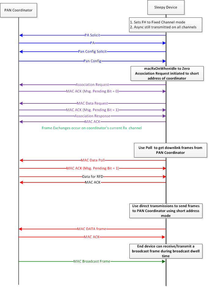
Figure 46. Sleep Mode Operation in Frequency-Hopping Mode
Maintaining a Connection for End Nodes
In a typical star network, the devices have to keep track of unicast and broadcast timing of Coordinator’s hopping sequences while the coordinator has to do for the unicast timing information of all the connected devices.
The timing information of the unicast and broadcast sequence of a device is carried in unicast timing and frame type information element (UTT-IE) and broadcast timing Information element (BT-IE), respectively. All data frames with destination address mode set to extended or None shall carry UTT-IE and BT-IE. The ACK frames from PAN-Coordinator will contain both the UTT-IE and BT-IE irrespective of address mode, while those from other non-sleepy end devices will carry UTT-IE alone. The timing information corresponding to the source of the received Data/ACK frame is updated based on received frames.
The lifetime of a neighbor table is based on the last time the entry was
updated. As long as a frame is received from a neighbor once every neighbor
valid time, it is kept active. The neighbor valid time for a hopping neighbor
is set to 2 hours by default. Neighbor valid time can be changed using the
MAC_FHPIB_NEIGHBOR_VALID_TIME PIB attribute. After that period the entry is
considered as expired. Any neighbor table entry is deleted if it is not updated
within the last 10 hours.
The period within which at least one data frame should be exchanged to maintain reliable communication depends on the dwell time value used by the PAN coordinator. TI recommends keeping this period for at most 10 minutes or 25 minutes, for a PAN coordinator dwell time of 100 ms and 250 ms respectively.
Disassociating
The frequency-hopping mode also supports the disassociation command defined in IEEE 802.15.4, similar to the nonfrequency-hopping mode.
Stack Configuration Knobs
The frequency-hopping mode features can be controlled through a set of MAC FHPIB attributes. Some of these PIBs affect TI 15.4-Stack operation directly, while others are provided to help applications generate the required Asynchronous frames. This section explains the MAC FHPIB attributes.
Parameters Controlling the Unicast Channel-Hopping Sequence of the Node
The parameters controlling the unicast hopping must be set after the FH is enabled and before the MAC or FH-start API is called (see Table 7.). These values must not be changed after the node starts the hopping sequence. To change these values the nodes have to be power cycled or reset.
| PIB | PIB ID | Range | Default | Description |
|---|---|---|---|---|
| ApiMac_FHAttribute_unicastDwellInterval | 0x2004 | 15 to 250 (ms) | 250 | Amount of time spent on each channel |
| ApiMac_FHAttribute_unicastChannelFunction | 0x2008 | 0 or 2 | 0 | Whether to hop or not. Only two values are supported: 0 – Fixed 2 – DH1CF-based hopping |
| ApiMac_FHAttribute_unicastFixedChannel | 0x200C | 0 – maximum channel based on PHY configuration | 0 | The channel to use during unicast hopping when the channel function is fixed |
| ApiMac_FHAttribute_unicastExcludedChannels | 0x2002 | 17 bytes | All zeros | The list of channels to avoid when channel function is 2. Each bit represents a channel, starting from the LSB of the first byte which, represents Channel 0 |
Parameters Controlling the Broadcast Channel-Hopping Sequence
These parameters must only be set on the PAN coordinator (see Table 8.). The parameters must be set after the FH is enabled and before the MAC or FH-start API is called. Other devices obtain this information on reception of a PC (an Asynchronous message) message from the PAN- Coordinator. Devices then perform their broadcast hopping based on the received configuration. The received configuration can be read from these PIBs after the reception of a PAN Config frame from the parent of a node.
| PIB | PIB Id | Range | Default | Description |
|---|---|---|---|---|
| ApiMac_FHAttribute_broadcastInterval | 0x2001 | 15 to 16777215 ms | 4250 | The interval between two different broadcast dwell interval |
| ApiMac_FHAttribute_broadcastDwellInterval | 0x2005 | 0 to 250 ms | 250 | Amount of time spent during broadcast dwell interval. Setting this value to 0 will disable broadcast transmissions. |
| ApiMac_FHAttribute_broadcastChannelFunction | 0x2009 | 0 or 2 | 0 | Whether to hop or not. Only two values are supported: 0 – Fixed 2 – DH1CF based hopping |
| ApiMac_FHAttribute_broadcastFixedChannel | 0x200D | 0 – maximum channel based on PHY configuration | 0 | The channel to use during broadcast dwell interval when the channel function is fixed |
| ApiMac_FHAttribute_broadcastExcludedChannels | 0x2003 | 17 bytes | All zeros | The list of channels to avoid when the channel function is 2. Each bit represents a channel, starting from the LSB of the first byte, which represents Channel 0. |
Note
A large value of broadcast interval implies a higher delay in transmitting broadcast frames. An application could decide to increase or decrease this interval based on the perceived requirement for handling broadcast frames.
On the device side, an application must set the source address of the chosen parent to the MAC TRACK PARENT PIB (see Table 9.). FH stack follows the broadcast hopping sequence of the chosen parent. An application can choose a parent based on the received source address of the PAN configuration frames. However, performance loss may occur due to loss in broadcast synchronization, which is corrected based on the subsequent PAN Configuration frame received from the new parent.
| PIB | PIB Id | Range | Default | Description |
|---|---|---|---|---|
| ApiMac_FHAttribute_trackParentEUI | 0x2000 | Any | 0xFFFFFFFF | Source address of the parent. |
Changing Broadcast Sequence Values in the Middle of Network Operation
A PAN coordinator may choose to modify the broadcast interval during a network operation. To do so the application of the PAN coordinator must set the values as required, and then increment the value of the MAC_FHPIB_BROCAST_SCHED_ID PIB (see Table 10.).
| PIB | PIB Id | Range | Default | Description |
|---|---|---|---|---|
| ApiMac_FHAttribute_broadcastSchedId | 0x200B | 0 to 65535 | 0 | A value representing a given broadcast configuration. It must be incremented when broadcast configurations are changed. |
Transmit PAN Config frames more frequently to enable the dissemination of this information to the network.
Note
The performance of the network may be affected during this change in configuration time as it requires some time for the nodes to update their hopping sequences.
Parameters to Control Frequency of the Operation of Hopping Mode
The following parameters can be set to control specific functions, as defined in Table 11..
| PIB | PIB Id | Range | Default | Description |
|---|---|---|---|---|
| ApiMac_FHAttribute_clockDrift | 0x2006 | 0 to 255 | 20 | Represents the accuracy of the system clock in ppm. A value of 255 implies that the information is not provided. |
| ApiMac_FHAttribute_timingAccuracy | 0x2007 | 0 to 255 | 0 | Accuracy of provided timing information in 10s of micro seconds. |
| ApiMac_FHAttribute_neighborValidTime | 0x2019 | 5 to 600 (minutes) | 120 | The time in minutes for which a hopping neighbor is considered valid after reception of a Data/ACK from it. |
TI recommends not changing the values listed in Table 11., and using the default values.
Parameters to Control Neighbor Table Size
The amount of heap memory occupied by the FH neighbor table can be controlled through FH PIB attributes. The total number of end devices supported must be less than 50. If a deployment only requires a lesser number of devices, a lower number of neighbor table entries can be specified, thereby allowing more heap for the application. When configuring the number of neighbor table entries, both non-sleepy and sleepy devices must be changed together with MAC_FHPIB_NUM_NON_SLEEPY_DEVICES set first.
| PIB | PIB Id | Range | Default | Description |
|---|---|---|---|---|
| MAC_FHPIB_NUM_NON_SLEEPY_DEVICES | 0x201b | 0 to 50 | 2 | Total number of non-sleepy neighbors supported. |
| MAC_FHPIB_NUM_SLEEPY_DEVICES | 0x201c | 0 to 50 | 48 | Total number of sleepy neighbors supported. |
Note
The number of non-sleepy and sleepy neighbors can only be configured before issuing a network start or FHAPI_start API. The total number of end devices supported must be less than 50. When configuring the number of neighbor table entries, both non-sleepy and sleepy devices must be changed together with MAC_FHPIB_NUM_NON_SLEEPY_DEVICES set first.
| PIB | PIB Id | Range | Default | Description |
|---|---|---|---|---|
| MAC_FHPIB_BASE_BACKOFF | 0x201a | 0 to 16 | 8 | Additional back off parameter on target channel to account for interference (ms). |
| MAC_FHPIB_NEIGHBOR_VALID_TIME | 0x2019 | 0 to 65535 (minutes) | 120 | The time in minutes for which a hopping neighbor is considered valid after reception of a Data/ACK from it. |
The MAC_FHPIB_BASE_BACKOFF enables FH devices to mitigate interference, which causes a higher delay for packet transmission when interference is observed. The interference mitigation feature can be disabled by setting this parameter to zero (although it is not recommended to do so). TI recommends not changing these values and using the default values.
Parameters to Enable Application Generate and Process Asynchronous Frames
The following PIB attributes represent different fields of the Asynchronous frames (see Table 14.). The attributes are used to generate the required IEs when an async request is made by application based on the async frame type. The TI 15.4-Stack is responsible for only using these PIBs to encode the async frames and does not use these values to make any decisions on its operation. It is up to the application to use these fields if needed to perform any relevant operation.
| PIB | PIB Id | Range | Default | Description |
|---|---|---|---|---|
| ApiMac_FHAttribute_panSize | 0x200E | 0 to 65535 | 0 | The size of PAN network |
| ApiMac_FHAttribute_routingCost | 0x200F | 0 to 255 | 0 | Zero for PAN Coordinator and Non- Zero for other devices. Actual metric used is beyond the scope of MAC. This can be used to choose a parent. |
| ApiMac_FHAttribute_routingMethod | 0x2010 | 0 or 1 | 1 | Specify the type of routing protocol used. Typical values are 0 – MHDS, 1 – RPL |
| ApiMac_FHAttribute_eapolReady | 0x2011 | 0 or 1 | 1 | Specify whether the node can support EAPOL to perform authentication and key exchange |
| ApiMac_FHAttribute_fanTPSVersion | 0x2012 | 0 to 255 | 1 | Wi-SUN FAN version number |
| ApiMac_FHAttribute_netName | 0x2013 | 32 bytes | All zeros | Null terminated string |
| ApiMac_FHAttribute_panVersion | 0x2014 | 0 to 65535 | 00000 | Must be incremented whenever a configuration changes such as broadcast information or GTK Hash values are changed. |
| ApiMac_FHAttribute_gtk0Hash | 0x2015 | 8 bytes | All zeros | The Hash value that can be used by the application to decide the validity of an exchanged GMK key with ID 0. |
| ApiMac_FHAttribute_gtk1Hash | 0x2016 | 8 bytes | All zeros | The Hash value that can be used by the application to decide the validity of an exchanged GMK key with ID 1. |
| ApiMac_FHAttribute_gtk2Hash | 0x2017 | 8 bytes | All zeros | The Hash value that can be used by the application to decide the validity of an exchanged GMK key with ID 2. |
| ApiMac_FHAttribute_gtk3Hash | 0x2018 | 8 bytes | All zeros | The Hash value that can be used by the application to decide the validity of an exchanged GMK key with ID 3. |
CC1190 PA/LNA Support
CC1190 PA/LNA can be used to enhance the transmit power of the device using the
external Power Amplifier. If the system uses an external CC1190 external PA/LNA,
the stack should be configured to use the appropriate power tables. This can be
achieved by setting the PIB attribute ApiMac_attribute_rangeExtender to 1.
It is required to set this attribute first before setting the PIB attribute
ApiMac_attribute_phyTransmitPowerSigned to set the required power level.
When CC1190 is enable the following output power values will only be supported:
18, 23, 25, 26 and 27 dbm. When other values are requested, a status of
ApiMac_status_invalidParameter will be returned. For the OOB TI 15.4-Stack
applications, CC1190 PA/LNA support can be enabled by setting the configuration
option CONFIG_RANG_EXT_MODE to APIMAC_HIGH_GAIN_MODE.
Bluetooth Low Energy Advertiser
The TI 15.4-Stack supports Bluetooth Low Energy (BLE) advertisements, specifically, non-connectable undirected advertisements in simultaneous operation with the TI 15.4 stack. Such simultaneous operation is available only on the dual-band devices such as the CC1350. The TI 15.4 stack uses uBLE (pronounced micro BLE) stack subsystem which is a tiny light-weight non-connection based protocol stack module that supports only BLE Broadcaster role. It does not operate using a separate TI-RTOS stack but is integrated in the application. This saves memory and overhead required to maintain a separate RTOS task. Since uBLE supports only BLE Broadcaster role, there is no strict timing constraint. Therefore uBLE radio operation have lower priority compared to 15.4 radio operations. This implies that 15.4 radio operations will preempt uBLE operations.
Note
The BLE advertisement payload is fully modifiable. Any of the out-of-box example sensor applications can be configured to enable BLE advertisements.
Configuring uBLE Stack
FEATURE_BLE: Defining this compile flag in features.h will compile the
BLE advertisement feature.:
/*! If defined, builds the image wih BLE Advertiser enabled */
#define FEATURE_BLE
CONFIG_BLE_SUPPORT: Apart from FEATURE_BLE this configuration must be
set to true in config.h::
/*! Enable BLE advertiser   */
#define CONFIG_BLE_SUPPORT          true
The BLE advertisement interval can be modified as follows in ble_adv.c::
#define DEFAULT_ADVERTISING_INTERVAL 2000
Note
The units are in terms of 0.625 milliseconds. Hence setting it to 2000 will result in BLE advertisements being sent out every 1.25 seconds.
Security
The TI 15.4-Stack supports AES encryption as defined by the IEEE 802.15.4 Specification. The application is responsible for management of the keys. The out-of-box example application of the TI 15.4-Stack demonstrates how to use security with the TI 15.4-Stack.
Configuring Stack
The TI 15.4-Stack offers three modes of network operations that follow (and as discussed in this chapter):
- Beacon mode
- Nonbeacon mode
- Frequency-hopping mode
- BLE Advertising Mode
The features.h file allows developers to compile-in or compile-out different
15.4-Stack features for different applications. TI 15.4-Stack allows support for
all three modes or allows user to select just one desired mode of network
operation. TI 15.4-Stack can be configured in four different modes of operation
using the features.h file. Depending on the mode selection, considerable
savings in the executable-image space can be achieved.
Table 15. and Table 16. provide a summary
of Flash and RAM use of the out-of-box Collector and Sensor Example Application
with different compile options enabled.
FEATURE_ALL_MODES: When this compile flag is defined, the image is compiled with all the three modes of operation (frequency-hopping mode, beacon-enabled mode and non-beacon mode) and the configuration fileconfig.hcan be used to select the specific mode for network operation. This feature allows flexibility to select any mode for the device. For the out-of-box collector and sensor example application, this feature is enabled.:/*! If defined, builds the image with all the modes of operation (frequency hopping, beacon mode and non beacon mode) */ #define FEATURE_ALL_MODES
FEATURE_FREQ_HOP_MODE: Defining this compile flag will compile only the frequency hopping mode of operation in the final executable image. For out of box example application, you would need to disable the compile optionFEATURE_ALL_MODESand then enable this compile option as in the following::/*! If defined, builds the image with all the modes of operation (frequency hopping, beacon mode and non beacon mode) */ #undef FEATURE_ALL_MODES /*! If defined, builds the image with the frequency mode of operation */ #define FEATURE_FREQ_HOP_MODE
FEATURE_BEACON_MODE: Defining this compile flag will compile only the beacon mode of operation in the final executable image. For out of box example application, you would need to disable the compile optionFEATURE_ALL_MODESand then enable this compile option as in the following::/*! If defined, builds the image with all the modes of operation (frequency hopping, beacon mode and non beacon mode) */ #undef FEATURE_ALL_MODES /*! If defined, builds the image with beacon mode of operation */ #define FEATURE_BEACON_MODE
FEATURE_NON_BEACON_MODE: Defining this compile flag will compile only the non-beacon mode of operation in the final executable image.:/*! If defined, builds the image with all the modes of operation (frequency hopping, beacon mode and non beacon mode) */ #undef FEATURE_ALL_MODES /*! If defined, builds the image with non beacon mode of operation */ #define FEATURE_NON_BEACON_MODE
FEATURE_BLE_SUPPORT: Defining this compile flag will enable BLE operations in the stack. CONFIG_BLE_SUPPORT will also need to be configured in config.h for the example application to send out BLE beacons.
In addition to the compile flags listed previously, the
FEATURE_FULL_FUNCTION_DEVICE compile flag is required for the PAN
Coordinator device (see the out-of-box Collector Example Application) to perform
the role as a central node in the network.
Also, the FEATURE_MAC_SECURITY compile flag is added in the features.h
file to allow the ability to turn the MAC layer security on and turn off in the
compile executable image. If the mac layer security is turned off, you will need
the version of the stack library with no MAC security.
To build the image with no security, perform the steps that follow:
Select the linker File Search Path option.
Modify to include the
maclib_nosecure.ainstead ofmaclib_secure.alibrary file (shown in Figure 47.).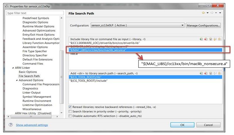
Figure 47. Changing TI 15.4 Stack library
The PREAMBLE_COMPATIBILITY compile flag allows the stack to be compatible
with previous versions of TI 15.4-Stack. When this flag is not defined the stack
uses a IEEE 802.15.4g compliant preamble. If this flag is enabled, a new version
of the stack library is required.
Similar to the steps above, to change the stack library for compatibility:
- Select the linker File Search Path option.
- Modify to include the
maclib_nosecureLegacy.aormaclib_secureLegacy.alibrary file depending on whether or not security is enabled or disabled.
| Compile Option Enabled | FLASH (KB) | RAM (KB) |
|---|---|---|
| FEATURE_ALL_MODES | 103 | 15 |
| FEATURE_FREQ_HOP_MODE | 98.1 | 14.6 |
| FEATURE_NON_BEACON_MODE | 84.6 | 13.9 |
| FEATURE_BEACON_MODE | 88.8 | 14.2 |
| Compile Option Enabled | FLASH (KB) | RAM (KB) |
|---|---|---|
| FEATURE_ALL_MODES | 103 | 13 |
| FEATURE_FREQ_HOP_MODE | 104.3 | 12.7 |
| FEATURE_NON_BEACON_MODE | 89.6 | 12.1 |
| FEATURE_BEACON_MODE | 92.1 | 12.1 |
Note
FEATURE_BLE_SUPPORT will add around 6KB of flash and 1.2KB of RAM
to any of the modes described above except for FEATURE_ALL_MODES.